Agilent Specifying Calibration Standards for the Agilent 8510 Network Analyzer Application Note 8510-5B Discontinued Product Information — For Support Reference Only — Information herein, may refer to products/services no longer supported. We regret any inconvenience caused by obsolete information. For the latest information on Agilent’s test and measurement products go to: www.agilent.com/find/products In the US, call Agilent Technologies at 1-800-829-4444 (any weekday between 8am–5pm in any U.S.
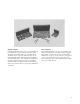
Table of contents Known devices called calibration standards provide the measurement reference for network analyzer error-correction. This note covers methods for specifying these standards and describes the procedures for their use with the Agilent Technologies 8510 network analyzer. The 8510 network analyzer system has the capability to make real-time error-corrected measurements of components and devices in a variety of transmission media.
Introduction This product note covers measurement calibration requirements for the Agilent 8510B/C network analyzer. All of the capabilities described in this note also apply to the Agilent 8510A with the following exceptions: response & isolation calibration; short circuit inductance; class assignments for forward/reverse isolation, TRL thru, reflect, line and options; and adapter removal.
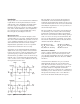
The array coefficients are computed by measuring a set of “known” devices connected at a fixed point and solving as the vector difference between the modeled and measured response. The full 2-port error model shown in Figure 1 is an example of only one of the measurement calibrations available with the 8510. The measurement calibration process for the 8510 must be one of seven types: RESPONSE, RESPONSE & ISOLATION, Sl l 1-PORT, S22 1-PORT, ONE PATH 2-PORT, FULL 2-PORT, and TRL 2-PORT.
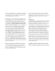
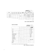
Standard definition Standard definition is the process of mathematically modeling the electrical characteristics (delay, attenuation and impedance) of each calibration standard. These electrical characteristics can be mathematically derived from the physical dimensions and material of each calibration standards or from its actual measured response. A standard definition table (see Table 1) lists the parameters that are used by the 8510 to specify the mathematical model.
Table 1. Standard definitions table Table 2.
Modification procedure Calibration kit modification provides the capability to adapt to measurement calibrations in other connector types or to generate more precise error models from existing kits. Provided the appropriate standards are available, cal kit modification can be used to establish a reference plane in the same transmission media as the test devices and at a specified point, generally the point of device connection/insertion.
Define standards A glossary of standard definition parameters used with the Agilent 8510 is included in this section. Each parameter is described and appropriate conversions are listed for implementation with the 8510. To illustrate, a calibration kit for WR-62 rectangular waveguide (operating frequency range 12.4 to 18 GHz) will be defined as shown in Table 1. Subsequent sections will continue to develop this waveguide example.
Each standard is described using the Standard Definition Table in accordance with the 1- or 2port model. The Standard Definition table for a waveguide calibration kit is shown in Table 1. Each standard type (short, open, load, thru, and arbitrary impedance) may be defined by the parameters as specified below.
It is not possible to remove fringing capacitance, but the resultant phase shift can be modeled as a function of frequency using C0 through C3 (C0 +Cl x f + C2 x f2 + C3 x f3,with units of F(Hz), C0(fF), C1(10-27F/Hz), C2(10-36F/Hz2) and C3(10-45F/Hz3), which are the coefficients for a cubic polynomial that best fits the actual capacitance of the “open.” A number of methods can be used to determine the fringing capacitance of an “open.
This method will serve as a first order approximation only, but can be useful when data or standards for the above modeling techniques are not available. For the waveguide example, this parameter is not addressed since opens cannot be made valid standards in waveguide, due to the excessive radiation loss and indeterminant phase. Figure 3.
The inductance as a function of frequency can be modeled by specifying the coefficients of a thirdorder polynomial (L0 + L1 x f + L2 x f2 + L3 x f3), with units of L0(nH), L1(10-24H/Hz), L2(10-33 H/Hz2) and L3(10-42H/Hz3). For the waveguide example, the inductance of the offset short circuits is negligible. L0 through L3 are set equal to zero. Fixed or sliding If the standard type is specified to be a load or an arbitrary impedance, then it must be specified as fixed or sliding.
The convention for definition of offset delay in waveguide requires entry of the delay assuming no dispersion. For waveguide transmission line, the Agilent 8510 calculates the effects of dispersion as a function of frequency as follows: Actual delay = For the WR-62 calibration kit, offset delay is zero for the “thru” (std #4) and the “load” (std #3). To find the offset delay of the 1/8 λ and 3/8 λ offset shorts, precise offset length measurements are necessary. For the 1/8 λ offset short, l = 3.
1 Z0 = 2π µ ε In ( ) = 59.9585 D d µr εr In ( ) D d µr = relative permeability constant of the medium (equal to 1.0 in air) εr = relative permittivity constant of the medium (equal to 1.000649 in air) D = inside diameter of outer conductor d = outside diameter of inner conductor The 8510 requires that the characteristic impedance of waveguide transmission line is assigned to be equal to the SET Z0.
Therefore, for the WR-62 waveguide standard definition table, offset loss of zero ohm/sec is entered for all four standards. Lower/minimum frequency Lower frequency defines the minimum frequency at which the standard is to be used for the purposes of calibration. Note When defining coaxial offset standards, it may be necessary to use banded offset shorts to specify a single standard class. The lower and upper frequency parameters should be used to indicate the frequency range of desired response.
Upper/maximum frequency This specifies the maximum frequency at which the standard is valid. In broadband applications, a set of banded standards may be necessary to provide constant response. For example, coaxial offset standards (i.e., 1/4 λ offset short) are generally specified over bandwidths of an octave or less. Bandwidth specification of standards, using minimum frequency and maximum frequency, enables the 8510 to characterize only the specified band during calibration.
Note Mathematical operations on measurements (and displayed data) after calibration are not corrected for dispersion. Enter WAVEGUIDE into the standard definition table for all four standards. Standard labels Labels are entered through the title menu and may contain up to 10 characters. Standard Labels are entered to facilitate menu driven calibration. Labels that describe and differentiate each standard should be used. This is especially true for multiple standards of the same type.
S11 A,B,C and S22 A,B,C S11 A, B,C and S22 A,B,C correspond to the S11 and S22 reflection calibrations for port 1 and port 2 respectively. These three classes are used by the Agilent 8510 to solve for the systematic errors; directivity, source match, and reflection tracking. The three classes used by the 7-mm cal kit are labeled “short,” “open,” and “loads.” “Loads” refers to a group of standards which is required to complete this standard class.
TRL Thru TRL Thru corresponds to the measurement of the S-parameters of a zero-length or short thru connection between port 1 and port 2. The Thru, Reflect and Line classes are used exclusively for the three steps of the TRL 2-PORT calibration. Typically, a “delay/thru” with zero (or the smallest) Offset Delay is specified as the TRL Thru standard. TRL Reflect TRL Reflect corresponds to the S11 and S22 measurement of a highly reflective 1-port device.
Each adapter is specified as a single delay/thru standard and up to seven standards numbers can be specified into the adapter class. Standard Class labels Standard Class labels are entered to facilitate menu-driven calibration. A label can be any userselected term which best describes the device or class of devices that the operator should connect. Predefined labels exist for each class.
Again, cal kit labels should be chosen to best describe the calibration devices. The “B.1” default suffix corresponds to the kit’s mechanical revision (B) and mathematical revision (1). Note To prevent confusion, if any standard definitions in a calibration kit are modified but a new kit label is not entered, the default label will appear with the last character replaced by a “*”. This is not the case if only a class is redefined without changing a standard definition.
User modified cal kits and Agilent 8510 specifications As noted previously, the resultant accuracy of the 8510 when used with any calibration kit is dependent on how well its standards are defined and is verified through measurement of a device with traceable frequency response. The published Measurement Specifications for the 8510 Network Analyzer system include calibration with Agilent calibration kits such as the 85050B.
Appendix A Calibration kit entry procedure Calibration kit specifications can be entered into the Agilent 8510 using the 8510 disk drive, a disk drive connected to the system bus, by front panel entry, or through program control by an external controller. Disk procedure This is an important feature since the 8510 can internally store only two calibration kits at one time while multiple calibration kits can be stored on a single disk.
Front panel procedure: (P-band waveguide example) 1. Prior to modifying or generating a cal kit, store one or both of the cal kits in the 8510’s nonvolatile memory to a disk. 13. Select WAVEGUIDE. 2. Select CAL menu, MORE. 15. Enter PSHORT 1 by using the knob, SELECT LETTER soft key and SPACE soft key. 14. Prepare to label the new standard: PRIOR MENU, LABEL STANDARD, ERASE TITLE. 3. Prepare to modify cal kit 2: press MODIFY 2. 4. To define a standard: press DEFINE STANDARD. 16.
4. Change the class label for S11A: LABEL CLASS, S11A, ERASE TITLE. 5. Enter the label of PSHORT 1 by using the knob, the SELECT soft key and the SPACE soft key. This completes the entire cal kit modification for front panel entry. An example of programmed modification over the GPIB bus through an external controller is shown in the Introduction To Programming section of the Operating and Service manual (Section III). 6. Complete the label entry procedure: TITLE DONE, LABEL DONE.
Appendix B Dimensional considerations in coaxial connectors This appendix describes dimensional considerations and required conventions used in determining the physical offset length of calibration standards in sexed coaxial connector families. Precise measurement of the physical offset length is required to determine the OFFSET DELAY of a given calibration standard. The physical offset length of one and two port standards is as follows.
7 mm Coaxial connector Note: 1.0mm, 1.85mm and 2.4mm connectors not shown, but similar to 3.5mm calibration planes. Type-N coaxial connector interface The location of the “calibration plane” in Type-N standards is the outer conductor mating surfaces as shown below.
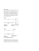
Appendix C Cal coefficients model Offset devices like offset shorts and offset opens can be modeled by the following signal flow graph : Figure 1 Signal flow graph model of offset devices The offset portion of the open or short, is modeled as a perfectly uniform lossy air dielectric transmission line. The expected coefficient of reflection, Γ, of the open or short then can be solved by signal flow graph technique.
Their first order approximations, R is small and G=0, are: Equation 3 Since Equation 4 For coaxial devices 30
then: Equation 5 Equation 6 If the Offset delay=0, then the coefficient of reflection, Γ = ΓL.
Agilent Email Updates www.agilent.com/find/emailupdates Get the latest information on the products and applications you select. Agilent Direct www.agilent.com/find/agilentdirect Quickly choose and use your test equipment solutions with confidence. Agilent Open www.agilent.com/find/open Agilent Open simplifies the process of connecting and programming test systems to help engineers design, validate and manufacture electronic products.