Agilent Upgrade Guide for the 8510 Vector Network Analyzer Product Note 85107B, 45 MHz to 50 GHz in coax 85106D with option 001, 45 MHz to 50 GHz in coax, above 50 GHz in waveguide 8510XF on-wafer configuration
Table of Contents 3 Vector network analyzer (VNA) overview 5 Agilent 8510 family of products 5 Agilent 8510 network analyzer 6 Agilent 8510 firmware upgrade kits 7 Test sets 8 9 9 9 Upgrading individual components Upgrading the 8510 10 Upgrading the 8510 to 8530 11 Test set upgrades 11 Expanding measurement capabilities 11 Adding pulse capabilities 11 Adding time domain capabilities 12 Upgrading systems 13 System upgrades 15 Examples of upgrade paths 15 Measurement accessories
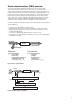
Vector network analyzer (VNA) overview Vector network analyzer (VNA) measurement systems are used to fully characterize the linear behavior of two port devices or networks. Device characteristics include the magnitude and phase data of the transmission or reflection parameters that are required to determine complex impedance, both resistive and reactive components, shown in Figure 1.
The Agilent Technologies 8510 network analyzer consists of a family of compatible products where each part is a separate system component. Each complete system includes the 8510 network analyzer, a test set, and compatible sources (measurement accessories are also needed to complete the measurement setup), shown in Figure 3. The frequency range of the measurement system is determined by the test set or the compatible source’s lesser frequency.
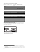
Agilent 8510 family of products 85106D Waveguide + systems Test set modules U-band Combined coax & Single-sweep high performance systems V-band Q-band W-band Waveguide 8510XF 85107B 8510SX 8510E 85108A (50 GHZ) 85108A* 85108L 20 GHz 45 MHz 2 GHz 26.5 GHz 50 GHz 75 GHz 110 GHz * 85108A also available in frequency range of 45 MHz to 20 GHz Figure 4.
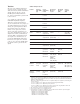
Table 2. Firmware revision and measurement capability Revision Time domain1 A.02.00 B.03.00 B.03.11 B.04.00 B.05.00 B.05.11 B.06.30 B.06.54 C.06.00 C.06.54 C.07.00 C.07.01 C.07.14 C.07.16 C.08.
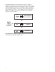
Test Sets The test set in a VNA measurement system is used to separate the incident, the reflected, and the transmitted signals. It is also used to convert the RF signal to IF (intermediate fre- quency) signal and to pass the IF to the receiver. Once signals are separated, their individual magnitude and phase differences can be measured.
Sources The RF or microwave signal source in a VNA measurement system provides the incident signal used to stimulate the device-under-test (DUT). The DUT responds by reflecting part of the incident and transmitting the remaining part. By sweeping the frequency of the source, the frequency response of the DUT can be determined. There are two types of sources available; the General Purpose (GP) 8360 series synthesized sweepers (836x0B) and the 8510-dedicated 8360 series synthesized sweepers (836x1B).
Upgrade considerations There are numerous reasons for upgrading the Agilent 8510 system. The 8510 network analyzer maintains excellent performance while adapting to different measurement requirements such as basic component testing, on-wafer probing, pulsed device characterization, antenna and RCS (Radar Cross Section) measurements. Depending on the application, the 8510 network analyzer system can be reconfigured to meet other system measurement needs.
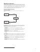
Upgrading the 8510 to the 8530 microwave receiver for antenna measurements Figure 7 below illustrates how the 8510C can be upgraded to either an 8530A or 8530A and 8510C. For example, to upgrade an 8510C to an 8530A, order 85395C with Option 111. 2 85395C Opt.111 8530A microwave receiver 2 8510C 85396A 85395C 8530A microwave receiver and 8510C network analyzer capability Figure 7. 8510 to 8530 upgrade paths Agilent 85395C2 Upgrades any 8510C to an 8530A. Retains network analyzer capability.
Test set upgrades A single 8510 network analyzer can be configured to control up to four test sets. The operator can switch between test sets, without reconnections, using front panel controls. This arrangement is often referred to as the multiple test set configuration. Each test set must be equipped with Option 001 for IF switching. Other requirements may apply for RF/LO switching.
Upgrading systems Figure 8 shows the different 8510 systems and their components. This figure is an excellent guide when upgrading systems. 85106D Waveguide systems Single-sweep high performance systems 33 to 110 GHz 8510C 85105A 83621B 83621B + OR Q-band U-band OR OR V-band W-band 0.045 to 110 GHz 8510C 85105A #050 8517B 83621B 83651B 8510E 8510SX 85107B 0.045 to 20 GHz 8510C 8514B 83621B 0.045 to 26.5 GHz 8510C 8515A 83631B 0.
Here is a checklist of items to consider when upgrading systems: 1. Which 8510 do I have? The 8510C is recommended for the latest available measurement capabilities. • To upgrade an 8510A to an 8510C, order 85103E. • To upgrade an 8510B to an 8510C, order 85103F. • Make sure the appropriate options are ordered. For instance, order Option 010 if the 8510 has previously installed time domain. • Do I need pulse capabilities? If yes, order 85111B for 8510C. 2.
Upgrades for 85107B, 85109C Upgrade consists of two test heads, a millimeter test set controller, an 83621B for LO source, and rack. It does not include calibration kits or test port cables. E7345A upgrade to an 8510XF 85 GHz system E7355A upgrade to an 8510XF 110 GHz system The following options are available for both upgrades: Option 005 add 45 MHz to 2 GHz low frequency extension Option 006 add RF pass thru (provides coupled output of 50 GHz source for additional test sets.
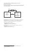
Examples of upgrade paths 85107B (45 MHz to 50 GHz) current system 8510C 8517B 83651B Upgrade to 85106D waveguide system to operate in V-band New equipment needed: ❑ 85105A1 with Option 0502 millimeterwave test set controller ❑ 83621B synthesizer (LO source) ❑ V85104A 3 test set modules (quantity of 2) ❑ V11644A 3 calibration kit ❑ V11645A 3 verification kit 8510C 85105A #050 8517B 83651B 83621B Figure 10.
Calibration kits Error correction requires that the systematic errors in the measurement system be characterized by measuring known devices (standards) over the frequency range of interest with the process of calibration. All calibration kits contain standards used for this purpose. The standards in the 3.5 mm, 2.4 mm and Type-N calibration kits use the precision slotless connector (PSC-3.5, PSC-2.4 and PSC-N). Unless otherwise noted all coaxial calibration kits include connector gauges and a torque wrench.
Verification kits Verification kits are used to verify the performance specifications of an 8510 system. All kits include a precision Zo airline, mismatched airline and fixed attenuators. Measured data and uncertainties traceable to the U.S. National Institute of Standards and Technology (NIST) are included with each kit. Compliance with MIL-STD 45662A is available for an extra charge Choose a verification kit for each connector type required.
Configuration B. This cable arrangement is for applications where the device under test is connected between cable ends. This setup offers more flexibility when connecting to the device under test. Configuration B Network analyzer test set For 8514B/8515A/85110A test sets (3.5 mm rugged test port connectors) Cables/adapter For 3.5 mm devices Connector type (on device side of cable/adapter) 85131D semi-rigid cable set or 85131F flexible cable set 3.5 mm (m and f) 3.
Related literature Pub.
For more information on the 8510 VNA visit: www.agilent.com/find/8510 www.agilent.com/find/emailupdates Get the latest information on the products and applications you select. Agilent Technologies’ Test and Measurement Support, Services, and Assistance Agilent Technologies aims to maximize the value you receive, while minimizing your risk and problems. We strive to ensure that you get the test and measurement capabilities you paid for and obtain the support you need.