
Specifications


2
1
4
3
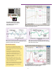
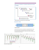
Phase-offset sweeps change the phase-
offset value as if it were added in the
fixture, enabling input-matching circuit
validation.
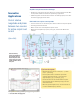
In-fixture phase-offset sweeps reveal the optimal phase offset to achieve the highest
amplifier gain, which is essential to the design of the input matching circuit.
Power or Gain
Phase Offset
(degrees from perfect differential)
+10 -10
Actual S
dd21
:
Peaked at -5 degree phase offset
Ideal Sdd21:
peaked at 0 degree phase offset
Differential
input power
-5 0
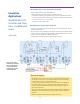
Various stimulus and sweep settings are available in the Balanced DUT
Topology dialog, which allow you to set the right setup for your devices
characterization.
Tips from the experts
• Input-only true-mode drive assumes a perfect match between the DUT output and
the VNA’s test ports, which is a good assumption when the DUT’s reverse isolation
is high. When the reverse isolation is low, adding attenuators on the output port
improves the system match and reduces mismatch errors.
• When comparing the test results between single-ended and true-mode drive
conditions with the same effective delivered differential power, the individual port
powers with true-differential drive must be set 6 dB lower than the port powers
used with single-ended drive.
Single-ended drive
0 dBm port power = -3 dBm differential power + -3 dBm common-mode power
True differential drive
-3 dBm port power = -6 dBm port 1 single-ended power + -6 dBm port 3 single-ended power
25