Errata Title & Document Type: 8590 E-series and L-series User's Guide Manual Part Number: 08590-90301 Revision Date: July 1998 HP References in this Manual This manual may contain references to HP or Hewlett-Packard. Please note that HewlettPackard's former test and measurement, semiconductor products and chemical analysis businesses are now part of Agilent Technologies. We have made no changes to this manual copy. The HP XXXX referred to in this document is now the Agilent XXXX.
User’s Guide HP 8590 E-Series and L-Series Spectrum Analyzers c?ii HEWLETT PACKARD HP Part No.
Notice. The information contained in this document is subject to change without notice. Hewlett-Packard makes no warranty of any kind with regard to this material, including but not limited to, the implied warranties of merchantability and fitness for a particular purpose. Hewlett-Packard shall not be liable for errors contained herein or for incidental or consequential damages in connection with the furnishing, performance, or use of this material.
Certification Hewlett-Packard Company certifies that this product met its published specifications at the time of shipment from the factory. Hewlett-Packard further certifies that its calibration measurements are traceable to the United States National Institute of Standards and Technology, to the extent allowed by the Institute’s calibration facility, and to the calibration facilities of other International Standards Organization members.
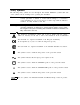
Safety Symbols The following safety symbols are used throughout this manual. Familiarize yourself with each of the symbols and its meaning before operating this instrument. Caution Caution denotes a hazard. It calls attention to a procedure that, if not correctly performed or adhered to, would result in damage to or destruction of the instrument. Do not proceed beyond a caution sign until the indicated conditions are fully understood and met. Warning Warning denotes a hazard.
General Safety Considerations Warning This is a Safety Class I product (provided with a protective earthing ground incorporated in the power cord). The mains plug shall only be inserted in a socket outlet provided with a protective earth contact. Any interruption of the protective conductor, inside or outside the instrument, is likely to make the instrument dangerous. Intentional interruption is prohibited. Warning No operator serviceable parts inside. Refer servicing to qualified personnel.
Caution VENTILATION REQUIREMENTS: When installing the product in a cabinet, the convection into and out of the product must not be restricted. The ambient temperature (outside the cabinet) must be less than the maximum operating temperature of the product by 4°C for every 100 watts dissipated in the cabinet. If the total power dissipated in the cabinet is greater then 800 watts, then forced convection must be used.
HP 8590 Series Spectrum Analyzer Documentation Description Manuals Shipped with Your Spectrum Analyzer HP 8590 E-Series and L-Series Spectrum Analyzers User’s Guide Describes how to prepare the analyzer for use. Describes analyzer features. Describes common applications. Tells how to make measurements with your spectrum analyzer. Includes error messages. Calibration Guide Provides analyzer specifications and characteristics. Provides manual procedures to verify specifications.
Contents 1. Preparing For Use What You’ll Find in This Chapter . . . . . . . . . . . . . . . . . . . . . . . Introducing the HP 8590 Series Spectrum Analyzers . . . . . . . . . . . . . Preparing Your Spectrum Analyzer for Use . . . . . . . . . . . . . . . . . . Initial Inspection . . . . . . . . . . . . . . . . . . . . . . . . . . . . . . . Power Requirements . . . . . . . . . . . . . . . . . . . . . . . . . . . . . Setting the Line Voltage Selector Switch . . . . . . . . . . . . . . . . . . .
3. Making Basic Measurements What You’ll Learn in This Chapter . . . . . . . . . . . . . . . . . . . . . . Resolving Signals of Equal Amplitude Using the Resolution Bandwidth Function . Resolving Small Signals Hidden by Large Signals Using the Resolution Bandwidth Function . . . . . . . . . . . . . . . . . . . . . . . . . . . . . . . . . Increasing the Frequency Readout Resolution Using the Marker Counter . . . . Decreasing the Frequency Span Using the Marker Track Function . . . . . . .
5. Using Analyzer Features What You’ll Learn in this Chapter . . . . . . . . . . . . . . . . . . . . . . . Use the Marker Table to List All the Active Markers . . . . . . . . . . . . . . Use the Peak Table to List the Displayed Signals . . . . . . . . . . . . . . . . Saving and Recalling Data from Analyzer Memory . . . . . . . . . . . . . . . ToSaveaState . . . . . . . . . . . . . . . . . . . . . . . . . . . . . . To Recall a State . . . . . . . . . . . . . . . . . . . . . . . . . . . . . . ToSaveaTrace . .
To Enter a Prefix . . . . . . . . . . . . . . . . . . . . . . . . . . . . 5-43 6. Printing and Plotting Printing or Plotting with HP-IB . . . . . . . . . Printing Using an HP-IB Interface . . . . . . . Equipment . . . . . . . . . . . . . . . . Interconnection and Printing Instructions . . . Plotting Using an HP-IB Interface . . . . . . . Equipment . . . . . . . . . . . . . . . . Interconnection and Plotting Instructions . . . Printing or Plotting with RS-232 . . . . . . . .
10. Measurement Personalities, Options, and Accessories What You’ll Find In This Chapter . . . . . . . . . . . . . . . . . . . . . . . Measurement Personalities . . . . . . . . . . . . . . . . . . . . . . . . . . Broadcast Measurements Personality . . . . . . . . . . . . . . . . . . . . CATV Measurements Personality . . . . . . . . . . . . . . . . . . . . . . CATV System Monitor Personality . . . . . . . . . . . . . . . . . . . . . . Cable TV Measurements and System Monitor Personality . . . . . . . . . .
Rack Mount Kit Without Handles (Option 908) . . . . . . . . . . . . . . . . Rack Mount Kit With Handles (Option 909) . . . . . . . . . . . . . . . . . IJser’s Guide and Calibration Guide (Option 910) . . . . . . . . . . . . . . . Service Documentation (Option 915) BenchLink Spectrum Analyzer (Option ‘B70) 1 1 1 1 : 1 : : 1 : : : : : : 1 1 Accessories . . . . . . . . . . . . . . . . . . . . . . . . . . . . . . . . . RF and Transient Limiters . . . . . . . . . . . . . . . . . . . . . . . . .
Figures l-l. HP 8590 Series Spectrum Analyzer . . . . . . . . . . . . . . . . . . . . . 1-2. Setting the Line Voltage Selector Switch . . . . . . . . . . . . . . . . . . . l-3. Checking the Line Fuse . . . . . . . . . . . . . . . . . . . . . . . . . . l-4. Reference Connector . . . . . . . . . . . . . . . . . . . . . . . . . . . . 1-5. Example of a Static-Safe Work Station . . . . . . . . . . . . . . . . . . . 2-l. Front-Panel Feature Overview . . . . . . . . . . . . . . . . . . . . . . . 2-2.
4-3. Block Diagram of a Spectrum Analyzer/Tracking-Generator Measurement System 4-4. Transmission Measurement Test Setup . . . . . . . . . . . . . . . . . . . . 4-5. Tracking-Generator Output Power Activated . . . . . . . . . . . . . . . . . 4-6. Spectrum Analyzer Settings According to the Measurement Requirement . . . 4-7. Decrease the Resolution Bandwidth to Improve Sensitivity . . . . . . . . . . 4-8. Manual Tracking Adjustment Compensates for Tracking Error . . . . . . . . 4-9. Normalized Trace . . . .
6-3. ThinkJet Printer Switch Settings . . . . . . . 6-4. HP-IB to Centronics Converter Setup . . . . . 6-5. Printer Configuration Menu Map . . . . . . . 6-6. HP 7475A Plotter Switch Settings . . . . . . . 6-7. Plot Configure Menu . . . . . . . . . . . . . 6-8. 9600 Baud Settings for Serial Printers . . . . . 6-9. Printer Configure Menu . . . . . . . . . . . 6-10. Connecting the HP 7550A/B Plotter . . . . . . 6-l 1. Baud Rate Menu Map . . . . . . . . . . . . 6-12. Plot Configure Menu . . . . . . . . . . . .
lhbles l-l. Accessories Supplied with the Spectrum Analyzer . . . . . . . . . . . . . . 1-2. Power Requirements . . . . . . . . . . . . . . . . . . . . . . . . . . . . l-3. AC Power Cables Available . . . . . . . . . . . . . . . . . . . . . . . . . 1-4. Static-Safe Accessories . . . . . . . . . . . . . . . . . . . . . . . . . . . 2-l. RF Output Frequency Range . . . . . . . . . . . . . . . . . . . . . . . . 2-2. Screen Annotation . . . . . . . . . . . . . . . . . . . . . . . . . . . . . 2-3.
1 Preparing For Use What You’ll Find in This Chapter This chapter describes the process of getting the spectrum analyzer ready to use when you have just received it. See “Preparing Your Spectrum Analyzer For Use” for the process steps. The process includes initial inspection, setting up the unit for the selected ac power source, and performing automatic self-calibration routines. Information about static-safe handling procedures is also included in this chapter.
Preparing Your Spectrum Analyzer for Use Detailed information for all of the steps in this process is included in this chapter. 1. Unpack the spectrum analyzer and inspect it. 2. Verify that all of the accessories and documentation has been shipped. 3. Check that the line voltage selector is set to the proper voltage. 4. Check that the correct fuse is in place. Warning Failure to ground the spectrum analyzer properly can result in personal injury.
Initial Inspection Inspect the shipping container for damage. If the shipping container or cushioning material is damaged, keep it until you have verified that the contents are complete and you have tested the spectrum analyzer mechanically and electrically. Table l-l contains the accessories shipped with the spectrum analyzer. If the contents are incomplete or if the spectrum analyzer does not pass the verification tests in the calibration guide, notify the nearest Hewlett-Packard office.
Power Requirements The spectrum analyzer is a portable instrument and requires no physical installation other than connection to a power source. Warning Failure to ground the spectrum analyzer properly can result in personal injury. Use an ac power outlet that has a protective earth contact. DO NOTdefeat the earth grounding protection by using an extension cable, power cable, or autotransformer without a protective ground conductor.
Checking the Fuse The recommended fuse is size 5 by 20 mm, rated F5A, 250 V (IEC approved). This fuse may be used with input line voltages of 115 V or 230 V. Its HP part number is 2110-0709. With an input line voltage of 115 V an alternate fuse can be used. In areas where the recommended fuse is not available, a size 5 by 20 mm, rated fast blow, 5 A, 125 V (ULXSA approved) fuse may be substituted. Its HP part number is 2110-0756.
Power Cable The spectrum analyzer is equipped with a three-wire power cable, in accordance with international safety standards. When connected to an appropriate power line outlet, this cable grounds the instrument cabinet. Warning Failure to ground the spectrum analyzer properly can result in personal injury. Before turning on the spectrum analyzer, you must connect its protective earth terminals to the protective conductor of the main power cable.
lhble 1-3. AC Power Cables Available CABLE P L U G T Y P E * * PLUG DESCRIPTI’JN HP PART rIIJMl3ER CABLE COLOR :M 25O’J Strnight A BS1363A 9om E 0 L CABLE L E rl G T H F O R IJSE I II COUI‘JTR i ~INCHEC,) 2 2 9 ( 9 0 ) Mint Gray c;reot 2 2 9 Mint Gray /:yprus, (90) Brltuin. I‘Nigerin.
Turning on the Analyzer for the First Time When you turn the spectrum analyzer on for the first time, you should perform frequency and amplitude self-calibration routines to generate correction factors and indicate that the unit is functioning correctly. The spectrum analyzer should be allowed to warm-up for 30 minutes before performing the self-calibration routines. See “When Is Self-Calibration Needed?” in Chapter 2 for helpful guidelines on how often the self-calibration routines should be performed.
001 (7562 input), use the 750 calibration cable shipped with the analyzer. Use only 750 connectors to avoid damage to the RF input connector. Note Option 105 only: Remove all connections to the GATE TRIGGER INPUT rear-panel connector before performing the self-calibration routines. 6. Perform the frequency and amplitude self-calibration routine by pressing (CAL) and CAL FREQ & AMPTD . During the frequency routine, CAL: SWEEP, CAL: FREQ, and CAL: SPAN are displayed as the sequence progresses.
Performing the YTF Self-Calibration Routine For preselected spectrum analyzers (HP 8592L, HP 85933, HP 8595E, and HP 85963) only, the yig-tuned filter (YTF) self-calibration routine should be performed periodically. See “When Is Self-Calibration Needed?” in Chapter 2 for helpful guidelines on how often the self-calibration routines should be performed. To perform the YTF self-calibration routine, use the following procedure: 1.
Electrostatic Discharge Electrostatic discharge (ESD) can damage or destroy electronic components. All work on electronic assemblies should be performed at a static-safe work station. Figure l-5 shows an example of a static-safe work station using two types of ESD protection: H Conductive table-mat and wrist-strap combination. n Conductive floor-mat and heel-strap combination. Both types, when used together, provide a significant level of ESD protection.
Reducing Damage Caused by ESD The following suggestions may help reduce ESD damage that occurs during testing and servicing operations. n Before connecting any coaxial cable to an spectrum analyzer connector for the first time each day, momentarily ground the center and outer conductors of the cable. w Personnel should be grounded with a resistor-isolated wrist strap before touching the center pin of any connector and before removing any assembly from the unit.
2 Getting Started What You’ll Learn in this Chapter This chapter introduces the basic functions of the HP 8590 Series spectrum analyzers. In this chapter you will: w Get acquainted with the front-panel and rear-panel features. n Get acquainted with the menus and softkeys. w Learn about screen annotation. n Make a basic measurement (the calibration signal). n Learn how to improve measurement accuracy by using self-calibration routines.
Figure 2-l. Front-Panel Feature Overview 5 [FREQUENCY], 6 INSTRUMENT STATE functions affect the state of the entire spectrum analyzer. Self-calibration routines and special-function menus are accessed with these keys. The green @‘EZi] key resets the spectrum analyzer to a known state. The m key accesses the current operating mode of the spectrum analyzer and allows you to change to any operating mode available for your spectrum analyzer.
Note If you wish to reset the spectrum analyzer configuration to the state it was in when it was originally shipped from the factory, use DEFAULT CONFIG . Refer to the DEFAULT CONFIG softkey description in Chapter 7 for more information. 7 Icopv) prints or plots screen data. (This requires Option 041 or 043.) Use @ZiK$ Plot Conf ig or Print Conf kg, and COPY DEV PRMT PLT before using Icopv). See Chapter 7 for more details.
16 100 MHz COMB OUT supplies a 100 MHz reference signal that has harmonics up to 22 GHz. Fbr the HP 85921, HP 8593E, or HP 8596E only. 17 Memory card reader reads from or writes to a memory card. The memory card reader is standard with an HP 85913, HP 85933, HP 85943, HP 85953, and HP 85963. It is also available for the HP 859OL, HP 8592L, and HP 8594L as Option 003. 18 RF OUT 5OD supplies a source output for the built-in tracking generator. Fbr Option 010 only. See liable 2-l.
Rear-Panel Features I SWEEP HIGH SWEEP OUTPVT N / O U T CTTLj \I I Ill cm ‘W I m \vJ EXJ TRlG I EXT IN UT(TTLj YBOARD ~ \ \:(3 SD KY OPTSEP B p ,“K,“ER LO OUT i -\1 In- FUSE AUX VIDEO OUTPUT 63 w WE P+ TU E ye I I TA ._.. _ ““TPUT AUX INTE\ ACE MON ,0/d- @ r--7 / (I fiy< OPTlOh 0 4 1 O P T I O N \~~~~ 0 4 3 Figure 2-2. Rear-Panel Feature Overview 1 EXT ALC INPUT allows the use of an external detector or power meter for automatic leveling control of the tracking generator.
4 GATE TRIGGER INPUT (‘ITL) accepts a TTL signal which acts as the gate trigger. In edge mode, the trigger event (positive or negative edge) initiates a gate delay. In level mode, the gate trigger input signal opens and closes the gate directly: TTL high sets the gate on; TTL low sets the gate off. When this input is unconnected, TTL is set high. For Option 105 only.
Caution Turn off the spectrum analyzer before connecting the AUX INTERFACE connector to a device. Failure to do so may result in loss of factory-correction constants. Do not exceed the current limits for the +5 V supply when using the AUX INTERFACE connector. Exceeding the current limits may result in loss of factory-correction constants. Do not use the AUX INTERFACE as a video monitor interface. Damage to the video monitor will result.
Data Controls Data controls are used to change values for functions such as center frequency, start frequency, resolution bandwidth, and marker position. The data controls will change the active function in a manner prescribed by that function. For example, you can change center frequency in fine steps with the knob, in discrete steps with the step keys, or to an exact value with the number/units keypad.
Step Keys The step keys allow discrete increases or decreases of the active function value. The step size depends upon the spectrum analyzer measurement range or on a preset amount. Each press results in a single step change. For those parameters with fixed values, the next value in a sequence is selected each time a step key is pressed. Changes are predictable and can be set for some functions. Out-of-range values or out-of-sequence values will not occur using these keys.
Screen Annotation Figure 2-4 shows an example of the annotation that may appear on a spectrum analyzer screen. The screen annotation is referenced by numbers and is listed in ‘Iable 2-2. The function key column indicates which front-panel key or softkey activates the function related to the screen annotation. Refer to Chapter 7 for more information on a specific function key. 1 9 8 9 E X T E 4 NAL AT 2 I MHz MHz 0 dB PG1 0 . 0 KEYBOARD dB ENPUT MIIR-TKK 3 9 9 .
The display will be compressed slightly when using the PAL or NTSC format for the MONITOR OUTPUT, instead of the normal format. The PAL and NTSC formats have less vertical resolution than the spectrum analyzer display. The top and bottom of the spectrum analyzer display are compressed slightly so that all of the information can be fit into the size required by the MONITOR OUTPUT. able 2-2.
‘Ihble 2-3. Screen Annotation for Trace, Trigger, and Sweep Modes Trace Mode W = clear write (traces A/B/C) M = maximum hold (traces A/B) V = view (traces A/B/C) S = store blank (traces A/B/C) M = minimum hold (trace C) Trigger Mode Sweep Mode F = free run C = continuous L = line S = single sweep V = video E = external T = TV (Ootions 101 and 102 onlv) Menu and Softkey Overview The keys labeled FREQUENCY, CAL, and MKR are all examples of front-panel keys.
Making a Measurement Caution Do not exceed the maximum input power. The maximum input power for the HP 8590L and HP 85913 is +30 dBm (1 watt) continuous, 25 Vdc (with 10 dB or more attenuation). The maximum input power for the HP 85921, and HP 85933 is +30 dBm (1 watt) continuous, 0 Vdc (with input attenuation of 10 dB or more in bands 1 through 4.) The maximum input power for the HP 85943, HP 8594L, HP 85953, or HP 85963 is +30 dBm (1 watt) continuous and 50 Vdc (ac-coupled) or 0 Vdc (de-coupled).
Figure 2-5 demonstrates the relationship between center frequency and reference level. The box in the figure represents the spectrum analyzer screen. Changing the center frequency changes the horizontal placement of the signal on the screen. Changing the reference level changes the vertical placement of the signal on the screen. Increasing the span increases the frequency range that appears horizontally on the screen. Note Spectrum analyzers with Option 001 or 011 display the amplitude values in dBmV.
Measurement Summary 1. Connect the spectrum analyzer CAL OUT to the INPUT 5OQ and press the (PRESET_) key. 2. Set the center frequency by pressing the following keys: [FREQUENCY), 300 CMHz). 3. Set the span by pressing the following keys: ISPAN), 20 m. 4. The calibration signal is 20 dB (two graticule divisions) below the top of the screen using these spectrum analyzer settings.
Improving Accuracy with Self-Calibration Routines Data from the self-calibration routine is necessary for spectrum analyzer operation. Executing the self-calibration routine regularly ensures that the spectrum analyzer is using current calibration data that improves the spectrum analyzer frequency and amplitude accuracy. Press the ICAL) key to view the self-calibration routine menus. The last softkey on this menu, labeled More 1 of 4 , provides access to additional self-calibration functions.
Note If the frequency calibration CAL FREQ and the amplitude calibration CAL AMPTD self-calibration routines are used, the frequency calibration should be performed before the amplitude calibration, unless the frequency data is known to be accurate. The CAL FREQ softkey starts the frequency self-calibration routine. This routine adjusts the frequency, sweep time, and span accuracy in approximately 2 minutes. The CAL AMPTD softkey starts the amplitude calibration routine.
Performing the YTF Self-Calibration Routine (HP 8592L, HP 85933, HP 85953, or HP 85963 Only) For HP 8592L, HP 85933, HP 85953, and HP 85963 spectrum analyzers only, the YTF self-calibration routine should be performed periodically. See “When Is Self-Calibration Needed?” in the following section for some helpful guidelines on how often the self-calibration routines should be performed. 1.
6. If accurate self-calibration is needed temporarily in a different environment, use CAL FREQ t AMPTD , but do not press CAL STORE . The temporary correction factors will be used until the spectrum analyzer is turned off or until CAL FETCH is pressed. Memory Card Insertion and Battery Replacement The memory card reader is available for the HP 859OL, HP 8592L, and HP 8594L as Option 003. Use the following information to ensure that the memory card is inserted correctly.
Changing the Memory Card Battery It is recommended that the memory card battery be changed every 2 years. The battery is a lithium commercial CMOS type battery, part number CR 2016 or HP part number 1420-0383. Note The minimum lifetime of the battery (under ordinary conditions) is more than 2 years. The date that the memory card battery was installed is either engraved on the side of the memory card or written on a label on the memory card.
Procedure to Change the Memory Card Battery The battery is located beside the card’s write-protect switch on the end opposite the connector. Caution The battery power enables the memory card’s memory to retain data. You can lose the data when the battery is removed. Replace the battery while the card is installed in a powered-up instrument. 1. Locate the groove along the edge of the battery clip. See Figure 2-9. 2. Gently pry the battery clip out of the card. The battery fits within this clip. 3.
Analyzer Battery Information The HP 8590 Series spectrum analyzers use a 3.6 V lithium battery to enable the spectrum analyzer memory to retain data. The date when the battery was installed is on a label on the rear panel of the spectrum analyzer. See Figure 2-10. The minimum life expectancy of the battery is 8 years at 25 “C, or 1 year at 55 “C.
3 Making Basic Measurements What You’ll Learn in This Chapter This chapter demonstrates basic spectrum analyzer measurements with examples of typical measurements; each measurement focuses on different functions. The measurement procedures covered in this chapter are listed below. n Resolving signals of equal amplitude using the resolution bandwidth function.
Resolving Signals of Equal Amplitude Using the Resolution Bandwidth Function In responding to a continuous-wave signal, a swept-tuned spectrum analyzer traces out the shape of the spectrum analyzer intermediate frequency (IF) filters. As we change the filter bandwidth, we change the width of the displayed response. If a wide filter is used and two equal-amplitude input signals are close enough in frequency, then the two signals appear as one.
Note When using an HP 8590L with Option 713 or an HP 8592L with Option 713, and the signal peak cannot be found, increase the span to 20 MHz by pressing ISPAN) 20 INIHz_). The signal should be visible. Press [PEAK SEARCH], (MKRJ, MK TRACK ON OFF (ON), then ISPAN_) 2 INIHz) to bring the signal to center screen. Then press MK TRACK Old OFF so that OFF is underlined to turn the marker track function off. 4.
Resolving Small Signals Hidden by Large Signals Using the Resolution Bandwidth Function When dealing with resolution of signals that are not equal in amplitude, you must consider the shape of the IF filter as well as its 3 dB bandwidth. The shape of the filter is defined by the shape factor, which is the ratio of the 60 dB bandwidth to the 3 dB bandwidth. (Generally, the IF filters in this spectrum analyzer have shape factors of 15:l or less.
3. Set the source to 300.2 MHz, so that the signal is 200 kHz higher than the calibration signal. Set the amplitude of the signal to -80 dBm (60 dB below the calibration signal). 4. Set the 300 MHz signal to the reference level by pressing MARKER -+REF LVL . [PEAK SEARCH), [MKR), then If a 10 kHz filter with a typical shape factor of 15: 1 is used, the filter will have a bandwidth of 150 kHz at the 60 dB point.
Increasing the Frequency Readout Resolution Using the Marker Counter Note This application cannot be performed using an HP 8590L with Option 713 or an HP 8592L with Option 713. The marker counter increases the resolution and accuracy of frequency readout. When using the marker count function, if the bandwidth to span ratio is too small (less than O.Ol), the Reduce Span message appears on the display. If Widen RES BW is displayed, it indicates that the resolution bandwidth is too narrow.
Decreasing the Frequency Span Using the Marker Track Function Using the spectrum analyzer marker track function, you can quickly decrease the span while keeping the signal at center frequency. Example: Examine a carrier signal in a 200 kHz span. 1. Press (PRESET], tune to a carrier signal, and place a marker at the peak. (If you are using the CAL OUT signal, place the marker on the 300 MHz calibration signal. Press C-1, 300 m, ISPAN), 200 IMHz), and [PEAK SEARCH).
Peaking Signal Amplitude with Preselector Peak Note This application should only be performed using an HP 8592L, HP 8593E, HP 8595E, or HP 85963. PRESEL PEAK works above 2.9 GHz only (bands 1 through 4). The preselector peak function automatically adjusts the preselector tracking to peak the signal at the active marker. Using preselector peak prior to measuring a signal yields the most accurate amplitude reading at the specified frequency.
Tracking Unstable Signals Using Marker Track and the Maximum Hold and Minimum Hold Functions The marker track function is useful for tracking unstable signals that drift with time. The maximum hold and minimum hold functions are useful for displaying modulated signals which appear unstable, but have an envelope that contains the information-bearing portion of the signal. MK TRACK ON OFF may be used to track these unstable signals. Use [PEAK SEARCH] to place a marker on the highest signal on the display.
5. The signal frequency drift can be read from the screen if both the marker track and marker delta functions are active. Press INIKR), MARKER A , Cm), MK TRACK ON OFF ; the marker readout indicates the change in frequency and amplitude as the signal drifts. See Figure 3-9. b MKR A-TRII 28.8 ktiz - 0 5 dB REF - 4 0 0 dBm #ATTEN 0 dB PEAK LOG 10 dB/ C E N T E R 1 0 4 9 2 7 5 MHZ RES ew 1 0 CHZ I 0 d 1 k/Afi: I “BW 10 kHZ S P A N 5 0 0 . 0 I-Hz SWP 3 0 m5ec Figure 3-9.
MKR 104.8813 MHz C E N T E R 1 0 4 8813 MHz RES BW 1 0 ktiz VEW 1 0 kHZ S P A N 5 0 0 . 0 kHz SWP 3 0 msec Figure 3-10. Viewing an Unstable Signal Using Max Hold A Annotation on the left side of the screen indicates the trace mode. For example, MA SB SC indicates trace A is in maximum-hold mode, trace B and trace C are in store-blank mode. See “Screen Annotation” in Chapter 2. 6. Press (j%?Fj, TRACE A B C to select trace B. (Trace B is selected when B is underlined.
Comparing Signals Using Delta Markers Using the spectrum analyzer, you can easily compare frequency and amplitude differences between signals, such as radio or television signal spectra. The spectrum analyzer delta marker function lets you compare two signals when both appear on the screen at one time or when only one appears on the screen. Example: Measure the differences between two signals on the same display screen. 1. Connect the spectrum analyzer CAL OUT to the INPUT 50R. Press @ZZY’).
4 MKA A 2!97 ATTEN 1 0 0 dEm REF MHz - 1 3 . 4 3 dB dB PEaK LOG 10 dB/ WA SB SC FC COAR C E N T E R 900 MHz RES EW 3 MHZ VBW 1 MHZ SPQN 1 600 GH.? SWP 2 0 msec Figure 3-13. Using the Marker Delta Function 5. The MARKER -+PK-PK softkey can be used to find and display the frequency and amplitude difference between the highest- and lowest-amplitude signals. To use this automatic function, press (MKR--t), More 1 of 2 , M&RKER -+PK-PK . See Figure 3-14. 16:21:03 12 MhR 1992 & R E F .
4. Press CFREQUENCY] to activate center frequency. Turn the knob clockwise slowly to adjust the center frequency until a second signal peak is placed at the position of the second marker. It may be necessary to pause occasionally while turning the knob to allow a sweep to update the trace. The first marker remains on the screen at the amplitude of the first signal peak. Note Changing the reference level changes the marker delta amplitude readout.
Measuring Low-Level Signals Using Attenuation, Video Bandwidth, and Video Averaging Spectrum analyzer sensitivity is the ability to measure low-level signals. It is limited by the noise generated inside the spectrum analyzer. The spectrum analyzer input attenuator and bandwidth settings affect the sensitivity by changing the signal-to-noise ratio.
6. Press (AMPLITUDE), ATTEN AUTO MAN . Press the step-up key (m) once to select 20 dB attenuation. Increasing the attenuation moves the noise floor closer to the signal. A “#” mark appears next to the AT annotation at the top of the display, indicating the attenuation is no longer coupled to other spectrum analyzer settings. 7. To see the signal more clearly, press 0 m. Zero attenuation makes the signal more visible.
A “#I’ mark appears next to the RES BW annotation at the lower-left corner of the screen, indicating that the resolution bandwidth is uncoupled. As the resolution bandwidth is reduced, the sweep time is increased to maintain calibrated data. Example: The video-filter control is useful for noise measurements and observation of low-level signals close to the noise floor. The video filter is a post-detection low-pass filter that smoothes the displayed trace.
Example: If a signal level is very close to the noise floor, video averaging is another way to make the signal more visible. Note The time required to construct a full trace that is averaged to the desired degree is approximately the same when using either the video-bandwidth or the video-averaging technique. The video bandwidth technique completes the averaging as a slow sweep is taken, whereas the video averaging technique takes many sweeps to complete the average.
i ?7 REF 0 *Bn MKR 1 8 1 . 7 3 MHz - 6 0 2 9 dBm *TEN 10 dR SMPL -17 LOG 10 dB/ - 771 “ I D AVG 25 AVG 25 WA SB SC FC CURR t C E N T E R Irnl 7 3 MHZ RES BW 1 0 0 CHz VBW 3 0 kHr SPAN 10.00 MHZ SWP 2 0 rnsec Figure 3-20. Using the Video Averaging Function Making Basic Measurements 3.
Identifying Distortion Products Using the RF Attenuator and Traces Distortion from the Analyzer High-level input signals may cause spectrum analyzer distortion products that could mask the real distortion measured on the input signal. Using trace B and the RF attenuator, you can determine which signals, if any, are internally generated distortion products. Example: Using a signal from a signal generator, determine whether the harmonic distortion products are generated by the spectrum analyzer. 1.
/ 1 C E N T E R 400 0 MHZ RES BW 1 0 MHZ “BW 300 kHZ I / 1 SPAiN 200 200 .o .o MHZ SWP 20 0 nl5P Figure 3-22. RF Attenuation of 10 dB Figure 6. Compare the response in trace A to the response in trace B. If the distortion product decreases as the attenuation increases, distortion products are caused by the spectrum analyzer input mixer.
Third-Order Intermodulation Distortion Two-tone, third-order intermodulation distortion is a common problem in communication systems. When two signals are present in a system, they can mix with the second harmonics generated and create third-order intermodulation distortion products, which are located close to the original signals. These distortion products are generated by system components such as amplifiers and mixers. Example: Test a device for third-order intermodulation.
To measure the other distortion product, press SPEAK SEARCH], NEXT PEAK . This places a marker on the next highest peak, which, in this case, is the other source signal. To measure the difference between this test tone and the second distortion product, press MARKER A and use the knob to adjust the second marker to the peak of the second distortion product. See Figure 3-25. J@ REF 0 PEAK LOG 10 dB/ dBm MHz MKR a I 025 - 5 4 . 0 4 dB ATTEN 40 dB t- WA SE S C FS CORR L CENTER 300.
Using the Analyzer As a Receiver in Zero Frequency Span The spectrum analyzer operates as a fixed-tuned receiver in zero span. The zero span mode can be used to recover modulation on a carrier signal. Center frequency in the swept-tuned mode becomes the tuned frequency in zero span. The horizontal axis of the screen becomes calibrated in time, rather than frequency. Markers display amplitude and time values.
44 REF 0 dBm ATTEN 1 0 dB PEAK LOG 10 dB/ I C E N TT EERR 330000 0000 MHz MHz #RES BW 1 MHZ VBW 33 0 00 kHz kHz I S P A NN 2 0 . 00 00 MHz MHz SW 2 00 msec msec Figure 3-26. Viewing an AM Signal 3. To demodulate the AM, press [Bw). Increase the resolution bandwidth to include both sidebands of the signal within the passband of the spectrum analyzer. 4. Next, position the signal peak near the reference level and select a linear voltage display.
Measuring Signals Near Band Boundaries Using Harmonic Lock Note This application should only be performed using an HP 8592L, HP 85933, HP 85953, or HP 85963. When measuring signals at or near a band crossing, use the lowest band having a specified upper frequency limit that will include the signal of interest. See specifications and characteristics in your calibration guide for your instrument for harmonic band specifications.
4Q REF 0 dBm LOG 10 dE/ ATTEN MKR a 2 0 0 . 4 M H z -2 0 2 dB 1 0 dB I I I I i , MARKER C C E N T E R 1 2 . 9 0 0 0 GHr RES BW 3 MHz “BW 1 MHZ S P A N 3 5 0 . 0 MHz SWP 2 0 msec Figure 3-28. Using Harmonic Lock Note The comb frequencies have a 100 MHz spacing. b REF MKR A 2 0 1 . 3 M H z dBm ATTEN 1 0 dB PEAK LOG 10 dE/ MARKER C C E N T E R 1 2 . 9 0 0 0 GHr RES B’*I 3 MHz S P A N 3 5 0 . 0 MHz SW 4 0 msec Figure 3-29. Harmonic Locking Off Making Basic Measurements 3.
Making Measurements What You’ll Learn in This Chapter This chapter demonstrates spectrum analyzer measurement techniques with examples of typical applications; each application focuses on different features. The measurement procedures covered in this chapter are listed below. n Measuring amplitude modulation using the fast Fourier transform function. w Stimulus-response measurements using the built-in tracking generator (Option 010 or 011).
Measuring Amplitude Modulation with the Fast Fourier Transform Function A Fourier transform, transforms time domain data (zero span) into the frequency domain. The fast Fourier transform (FFT) function of the spectrum analyzer allows measurements of amplitude modulation (AM). It is commonly used to measure AM at rates that cannot be measured in the normal frequency domain due to spectrum analyzer limitations on narrow resolution bandwidths.
If the FFT stop frequency is less than the highest harmonic of the AM modulation, than the FFT results may include aliased signals. That is, it will include some signals that are being displayed at the wrong frequency. The sweep time affects the sample rate and must be optimized to avoid aliasing. The single and continuous FFT functions require a specific spectrum analyzer setup before they can be activated. First, an AM signal is demodulated in the time domain.
10. To confirm that the resolution bandwidth and video bandwidth are correct for measuring the modulation amplitude, use the following procedure: a. Press (MKRI and use the knob to move the marker to the desired modulation signal. In this example, place the marker on the 60 Hz fundamental modulation signal. Note For HP 8590L with Option 713 or HP 8592L with Option 713 the resolution bandwidth must be left at about 100 kHz to accommodate frequency drift of the spectrum analyzer.
Note When the FFT measurement is active, pressing the CMEAS/USER) key will cycle between the MEASUSER and FFT menus. 4.7 REF .B SMPL LOG dBrn RTTEH MKR 1 . 8 1 7 LHZ - 4 5 . 2 5 dBrn No u5er Men” i@ dB 2, : I FFT S T A R T B HZ RES BW 18 k”Z .: “BW 9.8 k”Z I FFT S T O P 6 . 6 6 7 k”Z SWP 3 8 . 8 m5e.2 R Figure 4-2. Percent Amplitude Modulation Measurement Example 2: Use the automatic FFT measurement to look at 60 Hz AM modulation. 1.
b. Press (Bw) and decrease the resolution bandwidth using the Q) key, until measured signal amplitude drops. Then press @) to increase the bandwidth until the signal amplitude stops increasing and stays the same, or until the maximum resolution bandwidth is reached. Use the narrowest bandwidth that does not cause a change in the signal amplitude. Note As the resolution bandwidth is stepped down, the modulated signal must be re-centered on the spectrum analyzer display.
Stimulus-Response Measurements Note This application should only be performed using an HP 8590L or HP 85913 with Option 010 or 011, or using an HP 85933, HP 85943, HP 85953, or HP 85963 with Option 010. What Are Stimulus-Response Measurements? Stimulus-response measurements require a source to stimulate a device under test (DUT), a receiver to analyze the frequency-response characteristics of the DUT, and, for return-loss measurements, a directional coupler.
Using a Spectrum Analyzer with a Tracking Generator The procedure below describes how to use the built-in tracking generator system of the HP 85913 Option 010 spectrum analyzer to measure the rejection of a low-pass filter which is a type of transmission measurement. Illustrated in this example are the functions in the tracking-generator menu, such as adjusting the tracking-generator output power, source calibration, and normalization.
& REF dBm ATTEN 1 0 d8 PEAK LOG 10 dB/ / W A SB S C FC CORR 1 C E N T E R 900 900 MHZ MHZ CENTER RES BW 3 MHZ “BW 1 MHZ S PPAAN N1 800 1 800GHr GHr SWP 22 00 msec msec Figure 4-5. Tracking-Generator Output Power Activated 4. Put the sweep time of the analyzer into stimulus-response auto-coupled mode by pressing More 1 of 2 , then SWP CPLG SR SA until SR (stimulus-response mode) is underlined.
6. Decrease the resolution bandwidth to increase sensitivity, and narrow the video bandwidth to smooth the noise. In Figure 4-7, the resolution bandwidth has been decreased to 10 kHz. 40 REF 0 dBm ATTEN 1 0 dB PEAK LOG 10 dB/ V P St SC F! CO!a C E N T E R 4 4 3 6 MHZ #RES EW 1 0 kHz S P A N 5 0 0 . 0 MHz SWP 5 0 msec “BW 10 kHZ Figure 4-7. Decrease the Resolution Bandwidth to Improve Sensitivity Adjusting the resolution bandwidth may result in a decrease in amplitude of the signal.
Note If the automatic tracking routine is activated in a narrow resolution bandwidth, it usually is not necessary to use the tracking adjust again when increasing the resolution bandwidth. 7. To make a transmission measurement accurately, the frequency response of the test system must be known. To measure the frequency response of the test system, connect the cable (but not the DUT) from the tracking generator output to the spectrum analyzer input.
@ REF 0 darn PEAK LOG 10 dE/ DL - 6 da MKR 3 4 9 . 9 MHZ -ia 6 4 dB *TTEN 10 da 6 WA-SE S C FC COW \ 1. ----,.&-C E N T E R 4 4 3 6 MHz XRES BW 1 0 CHZ “BW 10 kHZ S P A N 5 0 0 . 0 MHz SWP 5 0 msec Figure 4-10. Measure the Rejection Range with Delta Markers Tracking Generator Unleveled Condition When using the tracking generator, the message TG UNLVL may appear.
Demodulating and Listening to an AM or FM Signal Note This application should only be performed using an HP 85913, HP 8593E, HP 85943, HP 85953, or HP 85963 with Option 102 or 103. The functions listed in the menu under Demod allow you to demodulate and hear signal information displayed on the spectrum analyzer. Simply place a marker on a signal of interest, activate AM or FM demodulation, and then listen. Example: 1. Connect an antenna to the spectrum analyzer input. 2.
Example: The signal can be continuously demodulated if the spectrum analyzer is in zero span. 1. Place the marker on a signal of interest as in steps 1 through 3 of the previous example. 2. If the signal of interest is the highest-amplitude on-screen signal, set the frequency of the signal to center frequency by pressing (MKR-1 then MK TRACK ON OFF (ON). If it is not the highest-amplitude on-screen signal, move the signal to center screen by pressing [ml and MARKER -CF. 3.
Triggering on a Selected Line of a Video Picture Field Note This application should only be performed using an HP 85913, HP 85933, HP 85943, HP 85953, or HP 85963 with Option 301 (Options 101 and 102 combined). With Option 301, you can trigger on a TV picture carrier signal. This example enables you to view a test signal transmitted during vertical retrace when the TV screen is blanked. 1. Press (j%KY). 2. Set the frequency of a picture carrier signal to center frequency. 3. Press (TRIG] and TV TRIG .
b REF 1 4 9 2 m” SHPL LIN MKR a5 0 0 0 p&PC 283 02 u” ATTEEJ 10 dB V A SB S C TS CORR C E N T E R 6 7 . 2 5 0 MHz YRES BW 1 MHZ VW 3 0 0 kHZ SPAN 0 HZ #SWP 1 0 0 met Figure 4-14. Triggering on an Even Field of a Video Format The default video format is NTSC. Press TV Standard, then PAL-M, PAL , or SECAM-L to select a different video format.
Making Reflection Calibration Measurements Typically, the calibration standard for reflection measurements is a short circuit connected at the reference plane (the point at which the test device will be connected-see Figure 4-15). A short circuit has a reflection coefficient of 1 (0 dB return loss); it thus reflects all incident power and provides a convenient 0 dB reference. TC O U T HP 85630A TEST SET OR DIRECTIONAL BRIDGE/COUPLER OR pu135e Figure 4-15.
4. Adjust the spectrum analyzer for measurement conditions or settings. Turn on the tracking generator and set the amplitude level by pressing (AUX], Track Gen , and setting SRC PWR ON OFF to ON. Set center frequency, span, and other settings. 5. Replace the DUT with a short circuit 6. Normalize the trace by performing the following functions: a. Press [ml, select B using TRACE A B C , then CLEAR WRITE B to display the reference trace in B. b. Press BLANK B to store the reference trace in B. c.
Using the Gate Utility to Simplify Time-Gated Measurements (Option 105 only) The time gate allows the user to control when a spectrum analyzer measurement begins and the length of time during which the measurement is made. The time gate is an RF signal switch that permits signal into the spectrum analyzer only while the switch, or gate, is closed.
The types of signals that can be measured using the time gate function include: Pulsed RF signals Time domain multiple access (TDMA) communication system signals Interleaved or intermittent signals Signals with transient spectra n n n n Time critical signals are present in many different applications. A few of the applications are listed below: n Digital cellular communication systems require measurements on pulse modulated TDMA signals.
lo. Press Define Gate. Use the GATE DELAY and GATE LENGTH keys to position the gate. Once gate delay or gate length are activated, use the knob and data entry keys can be used to position the two vertical gate markers. Select a time interval within the last half of the pulse is selected. 11. Turn the gate on by pressing GATE ON OFF so that ON is underlined. This activates the frequency domain window, which is the lower window.
Using the Time-Gated Spectrum Analyzer Capability Without the Gate Utility Note Option 105 is required to perform this application. Option 101, fast time domain sweep, is recommended in addition to Option 105, because it significantly increases the resolution available in the time domain. With Option 101, sweep times (in zero span) as fast as 20 ps can be used, otherwise the maximum sweep time is limited to >20 ms.
Note When Option 105 is enabled, it’interrupts the internal signal path of the spectrum analyzer, so several spectrum analyzer functions may not be available under all conditions. These conditions include: marker noise (MK NOISE ON OFF ), sample detection while in the frequency span mode, quasi-peak detection (Option 103), and AM/FM demodulation and TV sync trigger (Option 102).
hp E P F GTPOS LOG 10 dB/ V A VB W C FC CORP I I C E N T E R 5 0 0 0 0 MHr #RES B W 1 0 0 kH2 / # V B W 3 0 0 hHr S P A N 5 0 0 0 MHz #SWP 1 0 set Figure 4-19. Viewing Time-Sharing of a Frequency with a Spectrum Analyzer Trace display of the first signal, with the time gate on. Using the Time-Gated Spectrum Analyzer Capability to View Pulsed RF This example demonstrates how to use Option 105 to view two different pulsed RF signals.
Figure 4-20. Pulse Repetition Interval and Pulse Width (with Two Signals Present) Item Description of Items in Figure 4-20 1 Pulse repetition interval (PRI) of signal I. PRI is measured in time units. PRI is equivalent to l/PRF, where PRF is the pulse repetition frequency. 2 Pulse repetition interval (PRI) of signal 2. 3 Pulse width (7) of signal 1. Pulse width is also referred to as 7 (tau). 4 Pulse width (T) of signal 2. 5 Signal delay of signal 2.
Use the guidelines in Table 4-l when using Option 105 to view a pulsed RF signal. These are only guidelines, and the spectrum analyzer settings can be changed if necessary. ‘Ihble 4-l.
The following example demonstrates the rules for setting up a time-gated measurement. In this example, we are using two signal generators to generate two signals at the same frequency (50 MHz). The pulse generators “space” (interleave) the signals in time as well as pulse modulate the signals.
lttble 4-3. Signal Generator Test Setup Settings Setting Signal Generator 1 Signal Generator 2 Frequency 50 MHz 50 MHz Amplitude -1 dBm -10 dBm On On Pulse Modulation 1. Set the center frequency of the spectrum analyzer to the frequency of the modulated signal. Decrease the frequency span of the spectrum analyzer. If necessary, adjust the reference level of the spectrum analyzer so that the peak signal is displayed near the top graticule. & REF PEAK LOG 18 dB/ .B dBm ATTEN i!3 dB ,*, ,‘. :.
3. Turn the gate on by pressing [SWEEP], GATE ON OFF (so that ON is underlined). Using an oscilloscope makes it easier to ensure that the gate occurs during the pulsed RF signal. With GATE OUTPUT connected to the oscilloscope, you can adjust the gate length and gate delay so that the gate occurs near the end of the pulse (see Figure 4-24). 1 ?. 4 00 o f f s e t 2 1 000~1 V/d, ” 062 V dc 8 00 V,‘dtv o f f s e t : 7 5 0 0 rn” 1.000 1 dc 200 mV/dlv o f f s e t I .O.OOO V dc 0OO:l 4.
7. Set the video bandwidth to a value that is greater than 1 divided by the gate length. For this example, the video bandwidth must be greater than l/13 ~LS, or 80 kHz. Press Isw), VID BW AUTO MAN, 100 (kHz. The spectrum analyzer displays only signal 1, not Both signal 1 and signal 2 (see Figure 4-25). t REF .0 dBm ATTEN 10 dB I ,............ . . . . . . . . . . . . . . . . . . . . . . . . . . . . . . . . . .
4 00 offset 2 V/d, 4 062 ‘/ 1 Cj i) 0 1 dc B no V/d, L ‘; f f srj t 7’;L 6 rn‘/ 1.000 1 d s- 200 mVjd,v o f f s e t 0 000 ‘J .I 000.1 dr 4 00 offset 0 1.000 1 50.0 V/d1 d 000 ‘4 dc us/‘div Figure 4-26. Placing the Gate Output During the Second Signal Item Description of Items in Figure 4-26 1 Output from pulse generator 1. 2 Output from pulse generator 2. 3 Pulsed RF signal input to the spectrum analyzer. 4 Gate output from Option 105.
Figure 4-27 shows the first pulsed RF signal (contained in trace A), and the second pulsed RF signal (contained in trace B). & REF .G dBm fITTEN iG dB GTpos . . . . . . . . . . . . . . . . . . . . . . . . . . . . . . . . . . . . . . . . . . . . . . . . . . . . . . . . . . . . . . . . . . . . . . . . . . . . . . . . . . . . . . . . . . LOG 18 dG/ “I .#. ,". GATE GATE LENGTH DELAY 110 psec EDGE POL poS NEG GATE CTL EDFE LUL PREU MENU ItRES BW 186 kHz #UBW 1638 kHz I~SWP 12~ fic.
Setting the Gate Delay and Gate Length Properly, When NOT Using the Gate Utility If the gate delay and gate length are not set properly, you may not be viewing an accurate representation of a signal. For example, If the gate does not occur during the RF pulsed signal, the amplitude of the signal displayed on the spectrum analyzer is lower than the actual signal (see Figure 4-28). $7, 08;5d0B;21 OCT 18, 1998 ATTEN 10 dB GTPOS . . . . . . . . . . . . . . . . . . . . . . . . . . . . . . . . . . . . . . . . .
Note Refer to the guidelines in Table 4-l when measuring a signal with signal delay. To use Table 4-4 and Table 4-5: n Determine the pulse width of the signal you want to measure, then use Table 4-4 to determine the gate delay, resolution bandwidth, gate length, and video bandwidth spectrum analyzer settings. n Determine the pulse repetition rate of the signal, then use ‘fable 4-5 to determine the spectrum analyzer sweep-time setting.
Table 4-5. Sweep Time Settings Pulse Repetition Interval (PRI) Pulse Repetition Frequency (PRF) 550 ps 220 kHz 21 ms 100 ps 10 kHz 41 ms 500 ps 2 kHz 201 ms 1 ms 1 kHz 401 ms 5 ms 200 Hz 2.01 s 10 ms 100 Hz 4.01 s 16.7 ms 60 Hz 6.7 s 33.3 ms 30 Hz 13.4 s I Sweep Time (minimum) 50 ms 20 Hz 20.1 s 100 ms 10 Hz 40.1 s 200 ms 5 Hz 80.
TUNING CAL 386866688 Sweepsens <10M 0.0EElGS303 ZERO 211996616 Sweepsens Wide 0.080002030 FAST 56503057 Main Coil Sens 0.098835200 ME0 1114621728 FM Co11sens Er 0.958118558 SLOW 22348669 Wide 01s~ Err 2.590917587 PkOfst 28 Wdsc sweeprenr 0.000502140 TCXO -98 EYO A slope 5E-10 Last Cal Freq 18:18:33 NAR 84, 1992 Last Cal hmp 18:26:17 MAR 04, 1992 TRACKING GEN AOFST 3051 XOFST 3095 OCORR -22372 ASLOP 0.617283940 FSLOP 0.00EEEE168 XSLOP 8.
2. Press (jj], [FREQUENCY], GATE DELAY , 60 ms, 0 Hz, (SPAN), ZERO SPAN, [SWEEP), 200 GATE LENGTH , 60 ms, Gate Control , ms. The GATE CTL EDGE LVL softkey should have EDGE underlined, and should have POS underlined. EDGE POL POS NEG 3. Press Previous Menu , GATE ON OFF (so that ON is underlined) (see Figure 4-32). Note This procedure offers a qualitative functional check only.
4. To check the gate control function, press Cm], Gate Control, GATE CTL EDGE LVL so that LVL (level) is underlined (see Figure 4-33). & REF .0 dBm ATTEN 10 dB GTpOS ,.........: . . . . . . . . . . . . . . . . . . . . . . . . . . . . . . . . . . . . . . . . . . . . . . . . . . . . . . . . . . . . . . . . . . . . . . . . . . . . . . . . . . . . . . . . . . ;OG ,‘, %L ,’ : GATE OiLAY 60.000 Rlsec ,,, ~..~~.~.,,,,,,,,,,.,,,..,,,.,,.,,,......: ,,,,,,,,, : W,qSB : SC FC .........~......~~~~~~~.......
Using the One Button Measurements to Measure N dB Bandwidth, Percent Amplitude Modulation, and Third Order Intercept (TOI) The spectrum analyzer includes one-button measurement functions. With one key press they make accurate measurements of: w N dB Bandwidth n Percent Amplitude Modulation n Third Order Intermodulation The signal or signals being measured must be displayed before activating the measurement. Measurements are made continuously, updating at the end of each sweep.
Example: Measure the 6 dB bandwidth of the spectrum analyzer internal 9 kHz EM1 bandwidth. 1. On the spectrum analyzer, press CM), (ON), ISPAN), and enter 200 kHz. [PEAK SEARCH), C-j, MK TRACK ON OFF 2. Select the 9 kHz EM1 bandwidth by pressing Isw], EM1 BW Menu, and 9 kHz EM1 BW . 3. Press [MEAS/USER) and N dB PTS ON OFF (ON) to activate the N dB bandwidth function. 4. Read the measurement results in the upper left corner of the screen. 5.
5. Read the measurement results in the upper left corner of the screen, 6. Press % AM ON OFF (OFF) to turn the measurement off. Third Order Intermodulation Measurement (TOI) Use the TO1 one-button measurement to make quick and easy intermodulation measurements of microwave spectrum analyzers, mixers or converters. When the TO1 measurement is turned on there must be four signals on the display, two test signals and their two associated distortion products.
& REF 0 *m AlTEN 4 0 dB I I MKR a 1 025 MHz - 5 4 04 dB PEAK LUG 10 dB/ W A 58 S C FS CORR 1 I I CENTER 300.650 MHz XRFS RW 3 kH7 I I “RW 3 kH7 I I S P A N 5 0 0 0 MHz SW 1 7 CPT Figure 4-36. Third-Order Intermodulation Measurement Example: Use the TO1 function to make a measurement 1. Press ~%iSQ. Connect two equal amplitude signals with different frequencies, to the spectrum analyzer INPUT 500. 2.
Using the Power Measurement Functions to make Transmitter Measurements The power menu provides several powerful transmitter measurement functions that are easy to use. The measurements include: n Occupied Bandwidth n Adjacent Channel Power Ratio n Channel Power These transmitter power measurements can be used to measure analog and continuous carrier digital radios. The transmitted signal can be tones, noise, or a combination of tones and noise, without affecting the measurement accuracy.
1. Connect a signal to the spectrum analyzer INPUT 50% 2. Press Cm) and enter the frequency of your input signal to place the signal at the spectrum-analyzer center frequency. 3. Press C-J and adjust the reference level to bring the signal near the top of the display. 4. Press [MEAS/USER) and Power Menu to access the power measurement functions. Press Setup and CHANNEL SPACING to enter the value for the channel spacing. The span is automatically set to be three times the channel spacing value.
Adjacent Channel Power Ratio (ACP) The leakage of a transmitter into adjacent channels can be measured quickly and easily. Enter the channel spacing and channel bandwidth, and activate the adjacent channel power measurement. The spectrum analyzer computes and displays the ACP ratio of both the lower and upper adjacent channels, marking the higher of the two. The absolute carrier power is read out and vertical lines on the display mark the channel bandwidth edges.
m REF 20 0 OBrn SMPL LOG IO dB/ AT 30 dB SINGLE MEni COllT MEAS CENTER FREO i’ iii i i i I ACPGRbPH UP, OFF Iii WA 58 SC FS CDRR SFtlJO PreY10115 Men” CENTER 825 0300 MHZ WRES BW 1 0 kHZ X”BW 10 kHL SPAN 116 B KHZ SW 350 n,src Figure 4-38. Adjacent Channel Power 9. To use the extended Adjacent Channel Power function, press Previous Menu , then press ADJ CHAN POWER extd. Figure 4-39. Adjacent Channel Power Extended 10.
4 MKR a 90 0 kHL REF 1 SMPL LOG 13 dB/ SINGLE MLA> CONT SWEEP CENTER FREO ACPGRAPH a> OFF “A SB “C FS COW II I I I I M-r,’ I CENTER 825 0300 MHZ #MS BW 1 0 kHL GRPH MCR 01 O F F I I #“BW I I I 10 ktiZ I I I I U’ II SPAN 215 9 L.HL SW 651 msec Prevlo’Js _ ._ Figure 4-40. Adjacent Channel Power Graph 11. To enable the graph marker, press GRPH MKR OH OFF so (ON) is underlined. Delta frequency, delta amplitude, and absolute amplitude values are displayed for the marker position.
Channel Power Measurement The channel power function measures the total power in the selected channel bandwidth. The signal can be noise, tones, or a combination of noise and tones. The channel power function measures the power using an rms method. Enter the channel bandwidth and activate the channel power measurement.
8. A graph of the channel power as a function of frequency can be calculated and displayed by pressing PWRGRAPH ON OFF so (ON) is underlined. The numerical channel power results are not displayed. The top graticule line represents the power as indicated by the reference level (REF) displayed value. b REF 12 0 dBrn MYR R25 0900 MHZ -37 87 dB”l AT 30 dB SINGLE MEni SMPL LOG 10 OB/ CDllT ME&.
5 Using Analyzer Features What You’ll Learn in this Chapter This chapter introduces the features of the HP 8590 Series spectrum analyzers. These features can be used to manipulate measurement data and to make measurements more easily. In this chapter you will: n Use the marker table to list all the active markers. n Use the peak table to list the displayed signals. w Save and recall data from analyzer memory. w Save and recall data from the memory card. n Learn about creating limit lines.
Use the Marker ‘I);tble to List All the Active Markers The marker table function can be used to display a list of all of the active markers. It is sometimes necessary to keep track of several points on a signal trace. Multiple markers are swept measurements. The multiple markers feature allows you to place up to four markers on a trace. Using the marker table all the markers on the display are annotated in a window is activated or updated.
Example: Use the marker table to measure the calibrator signal. 1. Connect the CAL OUT signal to the spectrum analyzer INPUT 5OQ. Press C-1, [FREQUENCY), STOP FREQ , 2 GHz. 2. Press (PEAK SEARCH) and NEXT PK RIGHT to place the marker 1 on the 300 MHz cal signal. 3. Press [MKRFCTN), MK TABLE ON OFF (ON) to turn on the marker table function. 4. Press INIKR) SELECT 1 2 3 4 (2) to select marker 2. Press MARKER ON OFF (ON) to activate marker 2.
Use the Peak %ble to List the Displayed Signals The peak table function can be used to list the amplitude and frequency of up to 10 of the signals being displayed. This is done by pressing a single key, without having to put a marker on each signal. Multiple signals from components, such as oscillators and mixers, or from surveillance are automatically identified and listed. The information is updated at the end of each sweep. The peak table display can easily be copied to a printer.
Example: Use the peak table function to measure the calibrator signal and its harmonics. 1. Connect the CAL OUT signal to the spectrum analyzer INPUT 500 and press [PRESET_). 2. Press (PEAK display. SEARCH], More 1 of 2 and PK TABLE ON OFF (ON) to turn on the peak table 3. The displayed peaks are listed by amplitude with the highest amplitude signal listed first. The table can be sorted by frequency, instead of amplitude.
Saving and Recalling Data from Analyzer Memory This section explains how to save and recall state, trace, limit line, and amplitude correction factor data to and from spectrum analyzer memory. You can use STATE + INTRNL to store up to eight states in analyzer memory, and Trace + Intrnl to store many traces, limit-line tables, and amplitude-correction factors. Saving state data saves the spectrum analyzer settings, but not the trace data. Saving trace data saves the trace data and the state data.
To Save a Trace Saving trace data is very similar to saving state data. Saving trace data saves both the trace data and the state data. 1. Enter a screen title, if desired, by using (j-1 and Change Title . 2. Set up the trace to be stored. 3. Press ISAVE). If CARD is underlined, press INTERNAL CARD to select INTERNAL. 4- Press Trace -+ Intrnl . This accesses a menu displaying TRACE A , TRACE B , and TRACE C. 5. Press the softkey for the trace that you want to save: TRACE A , TRACE B , or TRACE C .
To Save a Limit-Line ‘lhble or Amplitude Correction Factors The procedure for saving limit-line tables or amplitude correction factors is similar to saving trace data. State and trace data is not recalled with limit-line tables or amplitude-correction factors. 1. Enter a screen title, if desired, by using (DlspLAv_], Change Title . The screen title is displayed when CATALOG REGISTER is used to catalog the trace registers.
‘able 5-l.
Saving and Recalling Data from the Memory Card Note Option 003 is required when using an HP 8590L or HP 8592L. The memory card provides additional memory for saving instrument states, traces display images, limit-line tables, amplitude correction factors, and programs. Each HP 857’00A battery-backed RAM card provides 32 kilobytes of memory. Several different memory cards are available with up to 512 kilobytes of memory. See “Accessories” in Chapter 10.
Preparing the Memory Card for Use Note Improper insertion causes error messages to occur, but generally does not damage the card or instrument. Care must be taken, however, not to force the card into place. The cards are easy to insert when installed properly. 1. Locate the arrow printed on the card’s label. 2. Insert the card with its arrow matching the raised arrow on the bezel around the card-insertion slot (see Figure 5-3). Figure 5-3. Inserting the Memory Card 3. Press the card into the slot.
To format a new card, press [CONFIG), More 1 of 3 , Card Conf ig , FORMAT CARD . The message If you are sure, press key again to purge data appears on the spectrum analyzer screen. Press FORMAT CARD again. (FORMAT CARD requires a double key press.) To catalog a memory card, press Cm), More 1 of 3 , Card Conf ig , Catalog Card.
To Recall a State l. Press m or [RECALL]. If INTERNAL is underlined, press INTERNAL CARD to select CARD. 2. Press Catalog Card then CATALOG STATES . Use the knob to highlight the state data to be retrieved. 3. Press LOAD FILE. State data can also be recalled by specifying the prefix and the register number: I. Use Change Prefix to enter the prefix, or use the existing prefix. 2. Press CRECALL]. If INTERNAL is underlined, press INTERNAL CARD to select CARD. 3. Press CARD + STATE. 4.
3+ Press Card --f Trace to access the menu that displays TRACE A , TRACE B , and TRACE C . 4. Select the trace in which you want the trace data stored by pressing TRACE A , TRACE B , or TRACE C. 5. Enter the register number that the trace was saved under and then press [ENTER]. The recalled trace is placed in view mode. To Save a Display Image l. Press [DISPLAY_) or t-j, Change Prefix . Use the softkeys to enter a prefix under which you want the state saved. A prefix can be one to seven characters long.
To Save Limit-Line Yhbles or Amplitude Correction Factors The procedure for saving limit-line tables or amplitude correction factors is similar to saving trace data. State and trace data is not recalled when the limit-line tables or amplitude correction factors are recalled. 1. Press CD’SPLAY) or C-1, Change Prefix to enter a new prefix or change the existing prefix. If you do not specify a prefix, the limit-line table will be saved with a file name consisting of I-(register number).
Saving and Recalling Programs with a Memory Card Programs (also called downloadable programs or DLPs) can be loaded into spectrum analyzer memory either by loading a program from a memory card or by defining a function with programming commands. (Remote programming ability is available with Option 041 or 043). The process of saving and recalling programs from the memory card is similar to saving state data. To save program information to the memory card use ALL DLP -+ CARD.
Bible 5-3.
Using Limit-Line Functions Limit lines provide an easy way to compare trace data to a set of amplitude and frequency parameters while the spectrum analyzer is sweeping the measurement range. An upper and/or lower limit line can be displayed. Every measurement sweep of trace A is compared to the limit lines. If trace A is at or within the bounds of the limit lines, LIMIT PASS is displayed. If trace A is out of the limit-line boundaries, LIMIT FAIL is displayed. Figure 5-4 shows a sample limit-line display.
3 hp ? 1 0 REF dB \ Ml/R ‘1<,1 c1 ““Hz “” -i? _ - 91- Iii ‘“’ ~iy?y$j dB/ WA VB VC FC CORR 1 l\l I \I I I I I \ C E N T E R 3 0 0 0 MHz #RES BW 3 MHz I I I VBW 3 0 0 kHz I I I I S P A N 2 0 0 . 0 MHz SWP 20 m5eiI Figure 5-4. Typical Limit-Line Display 5. Press Edit Limit then Edit Upper to create an upper limit line. The table defaults to frequency parameters, the second column should be labeled START-FREQ.
7. The table defaults to fixed parameters, the upper right corner of the table should be labeled FIXED. If it is labeled RELATIVE, press More 1 of 2 . Then press LIMITS FIX REL so that FIX is underlined. LIMITS FIX REL specifies whether or not the limit line is relative to the spectrum analyzer center frequency and reference-level settings. When time parameters are used, the RELATIVE format only affects the amplitude part of the coordinate pairs.
hr R;F REF 00 dBmdBm ATTEN 10 dB PEAK LCJG Ai, 50 0 00 0 M MHz H z S A V B VC F C COPR C EE NNTTEER R 33 00 00 0 MM HH z RES BW 3 MHz V BBWW 1 1 MHz MHz S PP AANN 55 00 00 0 M H z SWP 2 00 msec msec Figure 5-5.
Limit-Line Functions This section describes the limit-line functions in the order that they are usually used. Editing, Creating, or Viewing a Limit-Line Pressing (j-1, then Limit Lines accesses the softkey menus used for creating a limit line. Press Edit Limit to edit an existing limit-line table or. If no limit-line table currently exists this will allow you to create one. If a limit line exists currently, and you would like to purge it and create a new one, press Edit Upper, and More 1 of 2 .
Selecting the Limit-Line ‘lhble Format Press Edit Upper, Edit Lower, Edit Up/Low, or Edit Mid/Delt to editor createa limit-line table. Each of the edit softkeys represents a different type of limit-line table format. The choice of edit softkey depends upon whether you want an upper limit line only, a lower limit line only, or both an upper and a lower limit line.
segment. Limit lines are constructed from left to right. The segment is defined by its beginning point (see Figure 5-6). Note Up to 20 segments can be specified for an upper or lower limit-line table. When entering a limit-line segment, the frequency/time and amplitude values will be listed as asterisks (***) until new values are entered. The new segment will be listed last until both the frequency (or time) and the amplitude values have been entered.
Selecting the kequency or Time Coordinate Press SELECT FREQ , then enter a frequency value, or press SELECT TIME and enter a time value, for the segment. Regardless of the table format, a frequency/time coordinate must be specified. Note Limit line coordinates may be entered in terms of either frequency and amplitude, or time and amplitude. Press LIMITS FRQ TIME until the desired choice of either frequency or time has be selected (underlined).
Selecting the Segment Type Press SEGMENT TYPE , then FLAT, SLOPE, or POINT to specify the segment type. The segment type determines how to connect the coordinate point of the current line segment with the coordinate point of the next line segment. The segment type determines whether the line segment is horizontal, vertical, sloped, or a single point. The three segment types are: 1.
f?? F.‘EF PEAK LOG TYPE I 2 3 I I 2 0 0 0 3 00 00 00 350 0 FLAT MHz MHZ MHz SA V B V C F C CORR I-10 0 dPm SLOPE POINT - 4 I I h I 1 CENTER 300.0 MHz RES BW 1 MHz b 5 \ 0 4 Figure 5-7.
Completing ‘Ihble Entry and Activating Limit-Line Testing Pressing EDIT DONE blanks the limit-line table from the screen and accesses the menu with LMT TEST ON OFF and LMT DISP Y N AUTO softkeys. Pressing LMT TEST UN OFF turns the limit-line testing on and off. Pressing LMT DISP Y N AUTO (Y) turns the limit lines display on. Pressing LMT DISP Y N AUTO (N) turns the limit lines display off. Pressing LMT DISP Y N AUTO (AUTO) sets the limit line display to match the limit line test function.
Procedure for Creating an Upper and Lower Limit Line This is a basic procedure for creating a sample of upper and lower limit lines. The CAL OUT signal is used for the test signal. 1. Press @KY]. 2. Since this procedure uses the calibration signal as the test signal, connect the spectrum analyzer CAL OUT to the INPUT 50 D with an appropriate cable. 3. Set the spectrum analyzer controls as follows: FREQUENCY) 300 MHz h 50 MHz m3MHz 4. Press (j%ZW) and Limit Lines to access the limit-line menus. 5.
Note gegmenl Number Frequency 2 290 MHz -60 dBm - 7 5 dBm Slope 3 295 MHz -15 dBm -75 dBm Slope 4 297 MHz -15 dBm -75 dBm Slope 5 300 MHz - 15 dBm -29 dBm Slope 6 303 MHz - 15 dBm -75 dBm Slope 7 305 MHz -15 dBm -75 dBm Slope 8 310 MHz -60 dBm -75 dBm Flat 9 400 MHz -60 dBm -75 dBm Point Upper Amplitude Lower TYPC Amplitude When entering a limit-line segment, the frequency, and amplitude values will be listed as asterisks (***) until new values are entered.
To turn the limit-line testing on and off, use LMT TEST ON OFF . Use PURGE LIMITS to clear the limit-line tables. To remove the limit lines from the display, use LMT DISP Y N AUTO . Underlining Y displays the limit lines, N turns them off, and AUTO displays them if the testing is turned on or turns them off if testing is turned off.
Learn About the Analog+ Display Mode (Option 101 only) The analog+ display mode combines traditional analog display performance with digital display benefits. Analog+ display mode gives the spectrum analyzer the look and feel of older analog displays, such as the HP 8558B, but it has the added benefit of features common to digital displays.
Learn About the Windows Display The windows display feature is only available on the HP 85913, HP 85933, HP 85943, HP 85953, and HP 85963. Windows display mode splits the spectrum analyzer display into two frequency or time displays. When windows is first turned on, the top window will contain an inactive copy of the previous display. The lower window will be active and will display a subset of the frequency span of the upper window.
5. Press ZONE PK RIGHT and ZONE PK LEFT and observe the movement of the changes in the lower window. zone and the 6. Press WINDOWS ~ZOOM]. Now a full-sized display of the lower window will be displayed. Notice the increase in the displayed annotation. 7. Pressing WINDOWS INEXT) activates the upper window. A full- sized display of it will be shown, and the inactive lower window will not be displayed. Press WINDOWS (NEXT) again to activate the lower window and display it again.
Learn How to Enter Amplitude Correction Factors This section provides an overview of amplitude correction, a procedure for creating amplitude-correction data, and descriptions of the amplitude-correction functions. Refer to “Key Descriptions” in Chapter 7 for more information on a specific amplitude-correction function. Amplitude corrections provide an easy way to adjust trace data with a set of amplitude and frequency parameters while the spectrum analyzer is sweeping the measurement range.
Procedure for Creating Amplitude-Correction Factors This procedure demonstrates how to create and activate amplitude-correction data. Detailed descriptions of the amplitude-correction functions follow this procedure. 1. Press (-1. Note A signal is not used in this procedure for demonstrating how to create amplitude-correction data. Disconnect any cable on the spectrum analyzer input. 2. Set the center frequency to 300 MHz and the span to 500 MHz by pressing: CFRE4UENCY) 300 INIHz) ISPAN) 500 IIVIHz) 3.
4 P E F .O dBm ATTEI‘I I O dB PEAK LOG I 1 2 WA VB 4 5 2 3 3 0 00MHz 5 0 0 MHz 0 0 . 0 MHz 5 0 0 MHz 12 10 0 0 dB dB SC FC C E N T E R 3 0 0 0 MHz R E S B W 3 . 0 MHz VBW 1 MHz S P A N 500 0 MHz SWP 20 msec pu149a Figure 5-12. Completed Amplitude-Correction ‘Ihble 9. Press EDIT DONE when all the points have been entered. Use steps 10 and 11 to display corrected versus uncorrected amplitude trace data for trace comparison. 10.
Amplitude-Correction Functions This section describes the amplitude-correction functions in the order they are usually used. Editing or Viewing the Amplitude-Correction ‘lhbles Pressing COAL), More 1 of 4 , More 2 of 4, More 3 of 4, Amp Cor accesses the softkey menus for creating an amplitude-correction table. Note (PRESET) turns amplitude-correction factors off (if it is on), but does not clear an existing amplitude-correction table. Use PURGE AMP COR to clear an existing amplitude-correction table.
Selecting the kequency Coordinate Press SELECT FREQ , then enter a frequency value for the point. Note Only two frequency amplitude the same Note When entering amplitude-correction data, the frequency and amplitude values will be listed as asterisks (***) until new values are entered. Once the frequency value is entered, the segment is immediately sorted into the table according to this value. entries per frequency are used.
External Keyboard The HP C1405B keyboard with an HP Cl40560015 Adapter, is an IBM AT compatible keyboard that can be connected to the external keyboard connector on the rear panel of the spectrum analyzer (Options 041 or 043 only). The external keyboard allows a convenient way to enter screen titles and remote programming commands directly into the spectrum analyzer or to access the softkey functions.
‘Ihble 5-8. External Keyboard Functions (continued) The external keyboard operation with the spectrum analyzer is similar to its operation with a computer except for the following: SCROLL LOCK and NUM LOCK are fixed and cannot be changed. Pressing (NUM] displays the keyboard mode on the spectrum analyzer screen. The analyzer will not recognize the control characters or function keys. The keyboard supports a 244 character recall buffer.
Using the External Keyboard The following three example procedures demonstrate how to use an external keyboard to enter a screen title, programming commands, and a prefix. However, a brief procedure on installing your external keyboard is described first. More detailed information on using the external keyboard is found in the HP 8590 E-Series and L-Series Spectrum Analyzer and HP 8591 C Cable TV Analyzer Programmer’s Guide. External Keyboard Installation 1. Turn off the spectrum analyzer.
To Enter Programming Commands Refer to the HP 8590 E-Series and L-Series Spectrum Analyzer and HP 8591C Cable TV Analyzer Programmer’s hide for more information. 1. Press cF8_1 on the external keyboard to enter the mode for executing remote commands. 2. Type in a programming command (for example, type IP). 3. Press [ENTER_) on the external keyboard to execute the command.
6 Printing and Plotting You may obtain a permanent record of data displayed on the spectrum analyzer screen by using the (copy) key of the spectrum analyzer, and a printer or plotter. This chapter describes how to print or plot the results displayed on your spectrum analyzer screen. There are three different interfaces used for this purpose: HP-IB RS-232 w Parallel n n Printing or Plotting with HP-IB More than one instrument can communicate on the same HP-IB.
PRINTER.... 3 Per Page pu121 el Figure 6-l. Three Printouts Per Page Selecting any Hewlett-Packard printer results in three printouts per page before form feeding the page. One printout per page can be accomplished by manually form feeding each printout. This is done by pressing either the ~FORM FEED] hard key on the printer or the PRINTER SETUP soft key under the @CiFi’Cj hard key on the analyzer.
PLOTS... 4 REF 0 dB” P:Ac LJb ,a d3/ ATTEN ID 63 Per Page 1 ‘li B -en LT-:!, J IhI -II ~1L li 3s 1”. 8, -I., oi :: I I jl lF .L I ,,L” Xl E” xn w. “~_ LS< J 48, ““l bI iP&, I 605 ;u_ _*I
Printing Using an HP-IB Interface Equipment w HP 8590 Series spectrum analyzer equipped with Option 041. n HP 10833A (or equivalent) HP-IB cable.
If using the HP-IB to centronics converter, connect it and set the switches as shown in Figure 6-4. The HP-IB to centronics converter must be powered up after the switches are set. SPEr,TRIJM AIIAImYZER CONVERTER PRINTER &POSITION SWITCH Figure 6-4. HP-IB to Centronics Converter Setup Figure 6-5. Printer Configuration Menu Map 4. Turn on the spectrum analyzer and printer. If using the HP-IB to centronics converter, connect its power cable. 5. The printer usually resides at device address 1.
PRINTER SETUP Press this key to send a PRINTER RESET command to the printer. This will cause a form feed if any data has been sent to the printer since the last form feed. Set Colr Printer Press if connected to a Hewlett-Packard compatible color printer, then select the appropriate printer. Selecting any Hewlett-Packard printer results in three printouts per page.
Plotting Using an HP-IB Interface Equipment w HP 8590 Series spectrum analyzer with Option 041. w HP 10833A (or equivalent) HP-IB cable. n Any of the following plotters: q HP 7440A ColorPro plotter with HP-IB q HP 7475A plotter with HP-IB q HP 7550A/B plotter with HP-IB Interconnection and Plotting Instructions More than one instrument can communicate on the same HP-IB. Therefore, each device must have a unique HP-IB address.
Figure 6-7. Plot Configure Menu 4. Turn on the spectrum analyzer and the plotter. 5. The plotter usually resides at device address 5. To configure the plotter address to 5 on the spectrum analyzer, press: @Giq Press this key to access the configuration menu. P l o t Config Press this key to access the plotter menu. P l t P o r t Config Press this key to access the plotter configuration menu. PLT PORT RPIR PAR ( SO that HPIB is underlined) PLOTTER ADDRESS 5 IHz) 6.
For a multi-pen plotter, the pens of the plotter draw the different components of the screen as follows: Description Pen Number 1 Draws the annotation and graticule. 2 Draws trace A. 3 Draws trace B. 4 Draws trace C and the display line. 5 Draws user-generated graphics and the lower-limit line. 6 Draws the upper-limit line.
Printing or Plotting with RS-232 Printing Using an RS-232 Interface This section describes how to print using an RS-232 interface. It is critical that the printer and spectrum analyzer be configured to be compatible with each other. Particular attention should be paid to: Character Size g-Bits Parity OFF Baud Rate 9600 (typical) Handshaking DTR= YES, DUPLEX= FULL Equipment n HP 8590 Series spectrum analyzer with Option 043 (RS-232 interface).
El 12345 ‘m P A I IIT J E T DESKJET, :m,m 500/550 S E R I E S QUIETJET, OUIET.JEI PLIJS TH I NV,JET Figure 6-8.
Figure 6-9. Printer Configure Menu 3. Referring to Figure 6-9 select the printer configuration for your spectrum analyzer by pressing the appropriate keys: @xFiq Press this key to access the configuration menu. P r i n t Config Press this key to access the printer configuration menu. PRINTER SETUP Press this key to send a PRINTER RESET command to the printer. This will cause a form feed if any data has been sent to the printer since the last form feed.
EP LQ570 SML LRG Press this key if the spectrum analyzer is connected to an LQ-570 Epson or other compatible 24-pin print-head printer. Pressing this key to underline SML will allow two printouts per page and will print softkey labels if desired (see PRT MENU ON OFF ). This function is operational for Epson compatible printers only when SML is underlined. PRT MENU ON OFF Press this key so that ON is underlined to print the softkey labels with the spectrum analyzer printout.
Plotting Using an RS-232 Interface This section describes how to plot using an RS-232 interface. It is critical that the plotter and the spectrum analyzer be configured to be compatible with each other. Particular attention should be paid to: Character Size &Bits Parity OFF Baud Rate 1200 (typical) Handshaking DTR=YES, DUPLEX=FULL Equipment n HP 8590 Series spectrum analyzer with Option 043. n HP 24542G 9-25 pin RS-232 cable n HP C2932A 9-9 pin RS-232 cable (for use with LaserJet 4P and 4Plus.
If you are connecting an HP 7550A/B plotter you will need to use the 92224F (f-f) gender changer as shown in Figure 6-10. COMPUTER/MODEM Figure 6-10. Connecting the HP 7550A/B Plotter 3. Turn on the spectrum analyzer and the plotter. 4. Set the spectrum analyzer baud rate (see Figure 6-11). To set the spectrum analyzer baud rate to 1200 baud, press: (p5iFiq P l o t Config P l t P o r t Config PLT PORT SER PAR (so that SER is underlined) BAUD RATE 1200 CHz) pu 134P / Figure 6-l 1.
5. Set the baud rate on your plotter. Depending on the model, it may need to be OFF to set the baud rate. Refer to your plotter’s documentation. If you have an HP 7550A/B plotter, you need to configure it as follows: MODE STANDARD SERIAL (not ENHANCED) DATA FLOW REMOTE STANDALONE (not EAVESDROP) BYPASS ON or OFF (don’t care) HANDSHAKE HARDWIRE/DIRECT PARITY 8-BITS/OFF BAUD RATE 1200 (it will work at 9600) DUPLEX FULL Figure 6-12. Plot Configure Menu 6.
For a multi-pen plotter, the pens of the plotter draw the different components of the screen as follows: Description Draws the annotation and graticule. Draws trace A. Draws trace B. Draws trace C and the display line. Draws user-generated graphics and the lower-limit line. Draws the upper-limit line. Printing after Plotting or Plotting after Printing Pressing Icopv) without changing COPY DEV PRNT PLT produces the function last entered (a print or a plot).
Printing With a Parallel Interface This section describes how to print using a parallel interface. Equipment w HP 8590 Series spectrum analyzer equipped with Options 041 or 043 (parallel interface), w HP C2950A parallel printer cable.
[CONF I Gh- r COPY DEV PRNT PLT Plot Conf 14 r Set B&W Printer Set Colr Printer _? r H P B & W Pk IIdTER H P B & W 01540 r PAINTJET PRIIJTER DESYJET 310/55OC DE;vJET 5 4 0 Figure 6-14. Printer Configuration Menu Map 5. To print with a parallel interface press the following keys: piGiq Press this key to access the configuration menu. P r i n t Config Press this key to access the printer menu. Pm Port Conf ig Press this key to access the printer configuration menu.
EP MX80 SML LRG Press this key if the spectrum analyzer is connected to a MX-80 Epson or other compatible g-pin print-head printer. Pressing this key to underline SML will allow two printouts per page and will print softkey labels if desired (see PRT MENU ON OFF ). Pressing this key to underline LRG will allow only one printout per page and will not print the softkey labels.
Plotting to an HP LaserJet Printer This section describes how to plot to a LaserJet printer using either an RS-232 or parallel interface.
r COf’Y U E V P R N T PLT r PLTS/Pc, 1 2 4 Figure 6-15. Plot Configure Menu 4. Referring to Figure 6-15 select the plotter configuration for your spectrum analyzer by pressing the appropriate keys: 5. Configure your analyzer to plot to the LaserJet by pressing: pmiq Press this key to bring up the configuration menu. COPY DEV PRNT PLT so that PLT is underlined. PLTS/PG 1 2 4 Press this key to underline the number of plots per page desired. Choose 1, 2, or 4 plots per page (see Figure 6-2.
Key Descriptions This chapter describes functions and controls of the spectrum analyzer. The front-panel keys and softkey functions are listed alphabetically followed by a complete and detailed description. Brief descriptions for service functions have also been included in this chapter. However, for more detailed descriptions and information about the use of each function, refer to the respective service guide for your instrument.
Service Functions Two types of functions are available for service use only: w Service calibration functions. n Service diagnostic functions. These service functions are designed for service use only. However, brief descriptions for each function are provided in this chapter. For more detailed descriptions and information about the use of each function, refer to the Service Guide for your instrument. Service documentation can be obtained by ordering Option 915 through your HP Sales and Service office.
FM OFFST (Option 102 or 103 only) FM SPAN FREQ DIAG FRQ DISC NORM OFF GND REF DETECTOR MAIN COIL DR MAIN SPAN MIXER BIAS DAC (HP 8592L, HP 85933, HP 85953, or HP 85963 only) PRESEL DAC (HP 8592L, HP 85933, HP 85953, or HP 85963 only) QP DET ON OFF (Option 103 only) QP GAIN ON OFF (Option 103 only) QPD RST ON OFF (Option 103 only) QPD OFFSET (Option 103 only) STP GAIN ZERO SWEEP RAMP SWEEP TIME DAC X FINE TUNE DAC YTF DRIVER (HP 8592L, HP 85933, HP 85953, or HP 85963 only) YTF SPAN (HP 8592L
Analyzer Functions % AM ON OFF determines the percent of amplitude modulation of the largest displayed signal and its two sidebands. The sidebands are assumed to be entirely from amplitude modulation. If there are differences in the sideband amplitude, the larger value is used. The measurement runs continuously, re-executing at the end of each sweep. All three signal must be displayed. The frequency spacing of the sideband signals must be the same within the span accuracy of the measurement.
19.1-22 BAND 4 HP 8592L and HP 8593E only. locks onto harmonic band 4. Harmonic band 4 is preselected and has a specified tuning range of 19.1 to 22 GHz. Front-Panel Key Access: [FREQUENCY) 9 kHz EM1 BW allows a 6 dB resolution bandwidth of 9 kHz. This bandwidth is useful when performing electromagnetic interference (EMI) measurements. Front-Panel Key Access: m 1 2 0 kHz EM1 BW allows a 6 dB resolution bandwidth of 120 kHz.
ACCEPT QP DATA For Option 103 only. displays the quasi-peak amplitude value of the marker. See the HP 85913, HP 8593E, HP 85943, HP 85953, or HP 8596E Option 103 supplement documentation for more information. Front-Panel Key Access: [AUXCTRL) ACPGRAPH ON OFF turns the adjacent channel power graph ON or OFF. With ACPGRAPH ON the ACP ratio graph is calculated and displayed and the numeric results are not displayed.
ADJ CHAN PWR extd measures the power leakage into the adjacent channels and calculates the adjacent channel power ratio of both the upper and lower channels, with respect to the reference channel. ADJ CHAN POWER extd has an extended dynamic range compared with ADJ CHAN POWER. The extended range is measured by taking two different sweeps with different reference levels and combining the trace data. The displayed dynamic range is 104 dB and the log scale is set to 13 dB/ division.
ALC TEST HP 8590L or HP 8591 E with Option 010 or 011 only. breaks the leveling loop of the automatic leveling control in the tracking generator. This is a service diagnostic function and is for service use only. Refer to the service guide for more information. Front-Panel Key Access: ICAL) ALL DLP - CARD Requires Option 003 for an HP 859OL, HP 8592L, or HP 8594L. saves all the downloadable programs and key definitions that are in spectrum analyzer memory onto the memory card.
ANALOG+ ON OFF Fbr the HP 8591E, HP 8593E, HP 8594E, HP 8595E, or HP 8596E only. Requires Q&ion 101 or 301. turns on the analog+ display mode. This is a digital implementation of an analog display, combining the advantages of both types of displays. The display is made up of 401 horizontal points or trace elements. In the analog+ display mode each trace element can display from 1 to 40 dots, or measurements. Pressing ANALOG+ ON OFF makes dot density the active function.
ANALYZER ADDRESS Option U41 only. allows you to set the HP-IB address of the spectrum analyzer. The spectrum analyzer address is set to 18 by pressing DEFAULT CONFIG . Front-Panel Key Access: [??%i%7] ANALYZER GAINS displays the current value of the gain for various functional blocks within the spectrum analyzer. The gain values will vary depending on the current spectrum analyzer settings. This is a service diagnostic function and is for service use only. Refer to the service guide for more information.
[AUTO COUPLE] accesses the softkey menu of functions that can be coupled. (Coupled functions are functions that are linked: if one function is changed, the other function is changed.) The functions that can be auto-coupled are listed below: w Resolution bandwidth couples to span. n Video bandwidth couples to resolution bandwidth when the spectrum analyzer has a video-bandwidth to resolution-bandwidth ratio of 0.3. n Sweep time couples to span, resolution bandwidth, and video bandwidth.
HP 8592L, HP 8593E, HP 85954 and HP 8596E only. accesses the harmonic band menu and the band lock function. Selecting a harmonic band causes the spectrum analyzer to lock onto the specified harmonic band and automatically select the settings shown in Table 7-2. Band Lock ‘able 7-2. Center Frequency and Span Settings for Harmonic Bands Center Span Description O-2.9 Gz BAND 0 1.45 GHz 2.9 GHz Low-pass filtered, first harmonic mixing. 2.75-6.5 BAND 1 4.638 GHz 3.
BLANK CARD Requires Option 003 for an HP 859OL, HP 8592L, or HP 8594L. deletes all the files from the memory card. Pressing BLANK CARD displays the message: If you are sure, press key again to purge data. Press BLANK CARD again if you want to delete all files from the memory card. Front-Panel Key Access: (jj BND LOCK ON OFF HP 8592L, HP 85933, HP 8595E, and HP 8596E only.
CAL FREQ initiates a frequency self-calibration routine. Connect CAL OUT to the spectrum analyzer input before pressing CAL FREQ . If Option 105 is installed, remove the cable from the rear panel GATE INPUT before starting the self-calibration routine. Front-Panel Key Access: m CAL FREQ & AMPTD initiates both the frequency and amplitude self-calibration routines. Connect CAL OUT to the spectrum analyzer input before pressing CAL FREQ & AMPTD .
CARD -+ DISPLAY Requires Option 003 for an HP 85901, HP 8592L, or HP 8594L. recalls into spectrum analyzer memory a display image saved on the memory card. It does not recall the associated instrument state, but the restored display can be viewed and copied. Before recalling a display that was saved under a prefix other than the current prefix, change the current prefix to the prefix used when the display was saved.
saved under a prefix other than the current prefix, change the current prefix to the prefix used when the data was saved. If windows are being used, only the trace of the active window can be recalled. Pressing LOAD FILE is an alternate way to load trace data (but not recommended for recalling limit-line files or amplitude correction factor files) from the memory card into spectrum analyzer memory. See “Saving and Recalling Data from the Memory Card” in Chapter 5 for more information.
ATTEN PEAK LOG 10 HP859X 1 s t-40 2 LW-8 12 13 s AAAAA-21 S T A T E 18 1 dPPDG dOOOm5 s-222 t LW-22 dLW-222 D dLW-20 S A 0 STATE TRACE .s-22 s-l SB I S C F C 1 15-56-45 0 MAR MAR l9E9 1389 21:39 2 8 MAR 19R9 19 2 0 1 1 0 0 25:16 28 00.25:39 2 8 MAP MAP 1389 1989 DLP DLP STATE 21 2 2 2 3 1 1 1 08-45 5 7 07.45:40 06:41.00 2 9 0 5 0 7 MAR APR APP 198’3 13E9 1989 TRACE 0 2 3 2 7 STATE STATE 2 4 5 06:45.42 0 7 APP 1389 2 9 3 0 1 1 0 6 4 9 . 3 4 06 : 50.
CATALOG DISPLAY Requires Option 003 for an HP 859OL, HP 8592L, or HP 8594L. catalogs all of the display images that are on the memory card. A display image can be recalled to the spectrum analyzer by using the CARD+DISPLAY softkey. Front-Panel Key Access: @iZZiJ or m CATALOG DLP catalogs all of the downloadable programs (DLPs) that are in spectrum analyzer memory or on the memory card.
‘Ihble 7-4. Analyzer Memory Catalog Information* Callout Number Description of Items in Figure 7-2 1 Name of the catalog source. (Internal) 2 Bytes of spectrum analyzer memory used. (5082) 3 Total bytes of spectrum analyzer memory available. (65534) 4 Bytes used by item. (52) 5 Name of item. (S-HIFT) * This table is not applicable when using CATALOG REGISTER or CATALOG ON EVEWT Unlike saving to the memory card, data is saved as an item in spectrum analyzer memory.
The on event programming commands can be set remotely; see the HP8590 E-Series and L-Series Spectrum Analyzer and HP 8591C Cable TV Analyzer Programmer’s Guide for more information about setting the commands. When the on event programming commands have not been set, or when an instrument preset has been performed, pressing CATALOG ON EVENT displays the status of the on event programming commands as UNDEFINED.
CATALOG REGISTER displays the status of state and trace registers in spectrum analyzer memory. States 1 through 8 are displayed with the center frequency (denoted by CF) and span (denoted by SP). The status of trace registers 0 to the maximum number of traces is displayed also. If a trace, limit-line tables, or amplitude correction factors have been saved in the trace register, the screen title (denoted by “TL:“) is displayed, otherwise UNUSED is displayed.
A prefix can be cleared with the clear function. Press (CONFIG] or (-1, Change Prefix , YZ-# Spc Clear, Clear to clear the current prefix. The current prefix is blanked by pressing DEFAULT CONFIG . Front-Panel Key Access: C-1, I-j, (ml, or ISAVE) Change Title allows you to write a 53-character screen title across the top of the screen. The marker readout may interfere with the last 26 characters. The markers can be turned off by pressing Ir\nKR), More 1 of 2 , and MARKER ALL OFF .
CHANNEL POWER measures the power and power spectral density in the channel bandwidth specified by the user. Two vertical lines on the display indicate the edges of the channel bandwidth. The measurement can be made on a single sweep or to continuously update at the end of each sweep. The center frequency, reference level, and channel bandwidth must be set by the user. If PARAM AUTO MAN is selected (AUTO is underlined), other settings will be coupled and set automatically.
CLEAR WRITE A erases any data previously stored in trace A and continuously displays any signals during the sweep of the spectrum analyzer. This function is activated at power on and by pressing @ZZ7J. Changing the trace mode of trace C to clear write or minimum hold can change the trace mode of trace A. If trace A is in clear-write mode or maximum-hold mode when trace C is changed to clear write or minimum hold, the trace mode of trace A is changed to store blank.
CLEAR WRITE B erases any data previously stored in trace B and continuously displays any signals detected during the sweep of the spectrum analyzer. This function is activated at power on and by pressing (PRESET_). Changing the trace mode of trace C to clear write or minimum hold can change the trace mode of trace B. If trace B is in clear-write mode or maximum-hold mode when trace C is changed to clear write or minimum hold, the trace mode of trace B is changed to store blank.
CLEAR WRITE C erases any data previously stored in trace C and continuously displays any signals detected during the sweep of the spectrum analyzer. This function is activated at power on and by pressing (jj]. Changing the trace mode of trace C to clear write or minimum hold can change the trace mode of trace A and trace B. If trace A or trace B is in clear-write mode or maximum-hold mode when trace C is changed to clear write or minimum hold, the trace mode of trace A or trace B is changed to store blank.
COARSE TUNE DAC displays the analog output of the YTO coarse-tune DAC located on the A7 Analog Interface assembly. This is a service diagnostic function and is for service use only. Front-Panel Key Access: ICAL) COMB GEN ON OFF HP 859ZL, HP 8593E, and HP 8596E only. turns the internal comb generator on or off. Connect a cable between 100 MHz COMB OUT and the spectrum analyzer input. Front-Panel Key Access: Cm) CONF TEST initiates a variety of tests to check the major functions of the spectrum analyzer.
(copvl Option 041 or 043 only. initiates an output of the screen data, without an external controller, to a previously specified graphics printer or plotter. Refer to Chapter 6 of this manual or the HP 8590 E-Series and L-Series Spectrum Analyzer and HP 8591C Cable TV Analyzer Programmer’s Guide for detailed information about printing and plotting. The printer or plotter must have already been selected using (CONFIG) and either Plot Conf ig (for a plotter) or Print Conf ig (for a printer).
With PLTS/PG 1 2 4 , you can choose a full-page, half-page, or quarter-page plot. Press PLTS/PG 1 2 4 to underline the number of plots per page desired. If two or four plots per page are chosen, a softkey function is displayed that allows you to select the location of the plotter output on the paper. If two plots per page are selected, PLT _ -LOC _ _ is displayed. If four plots per page are selected, PLT _ ,LDC _ _ is displayed.
Note Printing and plotting require an optional interface. Generally, spectrum analyzers with an HP-IB interface set the plotter address to 5 and the printer address to 1. Spectrum analyzers with an RS-232 interface must have the baud rate set to match the baud rate of the printer or plotter being used. The HP 8590 E-Series and L-Series Spectrum Analyzer and HP 8591C Cable TV Analyzer Programmer’s Guide that comes with the optional interfaces details the different interfaces.
CPL VBW ON OFF Option 105 only. Option 101 is recommended. automatically selects the optimum video bandwidth if the gate length has been entered. If the gate length has not been determined, the video bandwidth will not be coupled to the gate length and an error message will occur. If a gate length is entered manually, the coupling will be turned off. Front-Panel Key Access: [SWEEP) CRT HORZ POSITION changes the horizontal position of the signal on the spectrum analyzer display.
‘Ihble 7-6. Default Configuration Values Front-Panel Key Access: @XX) DEFAULT SYNC restores the factory default values of the horizontal and vertical synchronization constants for the rear panel MONITOR output. CRT SYNC DEFAULT can be used to exit from the NTSC or PAL modes to return to the normal monitor output and use the default synchronization constants. Front-Panel Key Access: (-1 Define Option 105 only. Option 101 is recommended.
DELETE FILE function allows you to delete an item from spectrum analyzer memory or a file from the memory card. Use the step keys to view different sections of the directory and use the knob to select the file or item to delete. Pressing DELETE FILE causes a message to appear on the spectrum analyzer screen: If you are sure, press key again to purge data. Press DELETE FILE again if you want to delete the memory item.
DESKJET 310/55oc selects the HP DeskJet 310 or 55OC for color printing. Use this function if you have one of these color printers. This softkey can be accessed by pressing (-1, t h e n S e t C o l r P r i n t e r . Front-Panel Key Access: (@iGQ DESKJET 540 selects the HP DeskJet 540 for color printing. Use this function if you have this color printer. This softkey can be accessed by pressing (-1, then Set Colr Printer. Front-Panel Key Access: (wj DETECTOR PK SP NG Option 101 only.
DISPLAY -+ CARD Requires Option 003 for the HP 85901, HP 8592L, and HP 8594L. saves the current spectrum analyzer display image on the memory card for viewing or copying later. It does not save the spectrum analyzer state or trace, so it cannot be used to restore an instrument to the conditions at the time the image was saved. To save the current display image, press DISPLAY + CARD , use the numeric keypad to enter a number, and press [ENTER).
DWELL TIME Option 102 or 103 only. sets the dwell time for the marker pause, during which demodulation can take place in nonzero span sweeps. The dwell time can be set from 2 milliseconds to 100 seconds. Front-Panel Key Access: ljj) EDGE POL POS NEG Option 105 only. 0ption 101 is recommended. determines whether the gate triggers on the positive-going or negative-going edge of the signal at the GATE TRIGGER INPUT connector (on the rear panel of the spectrum analyzer).
EDIT LAST mr options 021, 023, and 024 only. Refer to the HP 8590 E-Series and L-Series Spectrum Analyzer and HP 8591 C Cable TV Analyzer Programmer’s Guide for more information. starts the DLP editor function and allows the most recent item that was being edited, in the DLP editor buffer, to be accessed again. The item will not be in the spectrum analyzer user memory until it is processed by the SAVE EDIT softkey.
Edit Up/Low UPPer allows you to view or edit the upper and lower limit-line tables simultaneously. Up to 20 entries are allowed for the upper and lower limit-line tables. With the upper and lower limit-line table format, the upper and lower limit-lines can be entered at the same time. With the upper and lower limit-line format, the frequency (or time), upper amplitude, and lower amplitude are specified.
ENTER PRI Option 105 only. Option 101 is recommended. accesses the menu for entering the value of the pulse repetition interval (PRI). A delta marker can be activated by pressing MARKER ON . The other menu functions can be used to manipulate the marker to indicate the pulse repetition interval value. Pressing DONE returns to the previous menu and makes the current value of the marker the pulse repetition interval.
ERASE MEM ALL allows you to purge all user state registers, all user trace registers, all mode registers, the editor buffer, Group delay normalization, all DLP memory, and all microprocessor stack data. The stack pointer is set to its power-up value. No system globals are erased and the calibration data is preserved. Pressing ERASE MEM ALL causes a message to appear on the spectrum analyzer screen: If youare sure,Press key againtopurgedata.
ERASE TRACEALL Note allows you to purge all the user trace registers 0 through TRCMEM. Pressing Dispose User Mem and then pressing ERASE TRACEALL causes a message to appear on the spectrum analyzer screen: If you are sure, Press key again to purge data. Press ERASE TRACEALL again if you want to dispose of the user trace registers. Press any other softkey if you do not want to dispose of user state registers. n If SAVE LOCK OM OFF is set to (ON), this function is disabled. .
EXIT SHOW removes the screen annotation left after pressing SHOW OPTIONS . Front-Panel Key Access: (j-1 EXIT Option 105 only. Option 101 is recommended. exits the gate utility returning to the gate control menu. The spectrum analyzer is returned to normal operation. The state of the spectrum analyzer becomes the state of the window that was active when exiting the gate utility.
FFT Menu accesses the menu of keys to initiate and evaluate a Fourier transform of the spectrum analyzer displayed data. Activating other spectrum analyzer functions will automatically exit the FFT function or will corrupt the display (see Table 7-7). ‘Ihble 7-7.
FM COIL DRIVE displays the output of the FM coil driver produced on the A7 Analog Interface assembly. This is a service diagnostic function and is for service use only. Front-Panel Key Access: (CAL] FM GAIN 0ption 102 or 103 only. adjusts the FM deviation display. The center graticule represents zero deviation. The top graticule is the positive deviation set by FM GAIN. The bottom graticule is the negative deviation set by FM GAIN. The range for FM gain is from 10 kHz to 500 kHz.
FREQ OFFSET allows the user to input a frequency offset value that is added to the frequency readout, to account for frequency conversions external to the spectrum analyzer. Offset entries are added to all frequency readouts including marker, start frequency, and stop frequency. Entering an offset does not affect the trace. Offsets are not added to the span. Frequency offsets are entered using the numeric keypad.
graphics unless the utility is entered with the new settings. Front-Panel Key Access: f,sWEEP) GATE CTL EDGE LVL Option 105 only. Option 101 is recommended. determines if the gate is enabled on the edge of the trigger input or on a threshold level of the input signal. If the gate control is set to EDGE, the edge of the input signal triggers the timer for the gate delay. When the gate control is set to LVL, the gate follows the positive level of the signal connected to GATE TRIGGER INPUT.
GATE UTILITY Option 105 only. @Zion 101 is recommended. accesses the softkey functions used for Option 105, the time-gated spectrum analyzer capability. It creates related time domain and frequency domain windows to set up the time gate and make measurements. The center frequency and reference level must be set correctly before entering the gate utility. There must be a TTL signal at the GATE TRIGGER INPUT on the rear panel, and GATE OUTPUT must be connected to EXT TRIG INPUT.
GRPH MKR ON OFF turns the graph marker ON or OFF. This softkey is available when ACPGRAPH is ON (for ACP or ACP extended measurements), or when PWRGRAPH is ON (for channel power measurements). For the ACPGRAPH, the delta frequency, ACP ratio, and channel power are displayed at the marker position. For the channel power graph, the frequency and channel power are displayed at the marker position. Front-Panel Access Key: fjMEAS/USER_J IHOLD) HP 859OL, HP 85921; and HP 8594L only.
INPUT Z 500 75n adjusts the voltage readout by 1.76 dB to correct for the difference between voltage and power measurements in a 750 system versus a 500 system. The impedance you select is for computational purposes only, since the actual impedance of 5OQ (7562 for Option 001) is set by internal hardware. The preset value can be changed by using a service function. Select the computational input impedance by pressing INPUT Z 50R 75R or by entering 75 or 50 using the numeric keypad.
LIMIT LINES When accessed by ISAVE), pressing LIMIT LINES stores the current limit-line tables in spectrum analyzer memory or on the memory card. When accessed by (m), pressing LIMIT LINES recalls limit-line tables from spectrum analyzer memory or the memory card. See “To Save a Limit-Line Table or Amplitude Correction Factors” or “To Recall Limit-Line Tables or Amplitude Correction Factors” in Chapter 5 for more information.
LINE activates the trigger condition that allows the next sweep to be synchronized with the next cycle of the line voltage. Front-Panel Key Access: m LMT DISP Y N AUTO displays any portion of the limit lines that are currently within the spectrum analyzer display boundary. If Y (yes) is underlined the limit lines are displayed. If N (no) is underlined they are not displayed. If AUTO is underlined, the display of the limit lines is dependent on LMT TEST.
Main Menu Uption 10.5 only. 0ption 101 is recommended. returns to the main gate utility menu from within the gate utility. Pressing Main Menu accessesthe Define Time, Define Gate, Define Coupling, UPDATE TIMEFREQ , and EXIT UTILITY softkeys. Front-Panel Key Access: Cm] MAIN SPAN displays the main-coil-span signal, MC-SPAN, from the span dividers on the A7 Analog Interface assembly. This is a service diagnostic function and is for service use only.
MARKER A-SPAN sets the start and stop frequencies to the values of the delta markers. The start and stop frequencies will not be set if the delta marker is off. Front-Panel Key Access: [YZGY] MARKERAUTO FFT functions exactly like the CONTINUS FFT softkey, if the spectrum analyzer is already in zero span. If the spectrum analyzer is not in zero span it activates a marker which must be placed on the signal that will have an FFT performed on it and MARKER+ AUTO FFT must be pressed again.
MARKER --STOP changes the stop frequency so that it is equal to the frequency of the active marker. This moves the active marker to the right edge of the display. Front-Panel Key Access: ljMKR--t] MARKER ALL OFF turns off all of the markers, including markers used for marker track and demodulation (demodulation is only available with Option 102 or 103). Marker annotation is also removed. Front-Panel Key Access: m MARKER AMPTD keeps the active marker at the requested amplitude on the screen.
MAX HOLD A maintains the maximum level for each trace point of trace A. Updates each trace point if a new maximum level is detected in successive sweeps. Front-Panel Key Access: (ml MAX HOLD B maintains the maximum level for each trace point of trace B. Updates each trace point if a new maximum level is detected in successive sweeps. Front-Panel Key Access: (iG%] MAX MXR LVL lets you change the maximum input mixer level in 10 dB steps from -10 dBm to -100 dBm.
MK COUNT ON OFF All E-Series and L-Series spectrum analyzers except HP 85901; with Q&ion 713. turns on the marker counter when ON is underlined. If no marker is active before MK COUNT ON OFF is pressed, a marker is activated at center screen. Press MK COUNT ON OFF (so that OFF is underlined), to turn the marker counter off. Press CNT RES AUTO MAN to change the marker counter resolution to an uncoupled value. An (*) may appear in the upper right of the display along with the message Marker Count.
MK TRACK ON OFF moves the signal that is nearest to the active marker to the center of the screen and keeps the signal there. MKR-TRK or CNTR-TRK appears in the upper-right corner of the display. An (*) may appear in the upper-right corner of the display while the spectrum analyzer is verifying that it has the correct signal. Pressing MK TRACK ON OFF , C-1, MARKER NORMAL, or MARKER ALL OFF turns off the marker-track function.
N dl3 PTS ON OFF automatically places two markers at points N dB from the highest point on the highest displayed signal, and determines the frequency difference between the two markers. N dB is the active function and the value of N is set by the user. The measurement defaults to 3 dB when it is first turned on. The measurement runs continuously re-executing at the end of each sweep. No other signal can appear on the display within N dB of the highest signal.
No User Menu NORMLIZE ON OFF is displayed if key number 1 has not been defined by the user. Key number I can be defined by remote programming commands (KEYCMD or KEYDEF). Front-Panel Key Access: [MEAS/USER] subtracts trace B from trace A and adds the result to the display line. The result is displayed in trace A. The trace data is normalized with respect to the display line even if the value of the display line is changed. This function is executed on all subsequent sweeps until it is turned off.
OCCUPIED BANDWDTH integrates the power of the displayed spectrum and puts markers at the frequencies containing a selected percent of the power. The measurement defaults to 99% of the occupied bandwidth power. The power-bandwidth routine first computes the combined power of all signal responses contained in the trace. For 99% occupied power bandwidth, it then puts markers at the frequencies at which 0.5% of the power lies to the right of the right marker and to the left of the left marker.
m and [RECALL) do not save the windows display mode. If the windows display mode is being used, the save state function saves the state of the currently active window. The recall state function recalls the stored state into the currently active window. See the DISPLAY --+ CARD and CARD ADISPLAY softkeys for information about saving the display. ‘Ihble 7-9.
PARAM AUTO MAN lets the user choose between automatically or manually setting the parameters used for the measurement functions under the Power Menu softkey. Parameters such as span, resolution bandwidth, video bandwidth, center frequency step size, detector mode, and sweep time are coupled so that they are automatically updated. With AUTO underlined when channel bandwidth or channel spacing are changed, the coupled parameters will be updated and another sweep will be taken and measured.
PEAK ZOOM finds the highest displayed signal and narrows the span to a value selected by the user. Pressing PEAK ZOOM the first time will make FINAL SPAN the active function so the user can input the destination span. The current FINAL SPAN value will be displayed. At that time the user can enter a span or press PEAK ZOOM again to use the displayed span. The peak zoom function sets the reference level to the signal amplitude and sets the center frequency step size to the signal frequency.
PLT _ _ LOC - - Option 041 or 043 only. selects the position of the plotter output. The highlighted portion of the softkey label indicates where the plot is to be output on the page. This softkey function appears only if two or four plots per page are selected when PLTS/PG 1 2 4 is pressed. Front-Panel Key Access: @Zi’@ PLT MENU ON OFF Option 041 or 043 only. allows the softkey labels to be plotted along with the spectrum analyzer display.
Power Menu accesses functions which make transmitter power measurements. The measurements are designed for analog radio or continuous carrier digital radio signals. If another front-panel key is pressed, exiting the power menus, press the (v) key twice to return to the last power menu that was being used. Front-Panel Key Access: CMEAS/USER) POWER ON IP LAST determines the state of the spectrum analyzer when the spectrum analyzer is powered on.
provides a convenient starting point for making most measurements. Pressing @Z%?i] displays softkeys used for accessing the operating modes available for your spectrum analyzer. See Table 7-10 and Table 7-11 for the conditions established by pressing (j-1. The instrument preset function performs a processor test, but does not affect CAL data. Pressing C-1 clears both the input and output buffers, but does not clear trace B. The amplitude values of trace C are set to the reference level.
‘Ihble 7-11. Common Preset Conditions A - B - A Amplitude correction factors Off Off Amplitude units default values Annotation and graticule display on Attenuation 10 dB (auto-coupled) Center frequency Refer to Table 7-10. CF step size 10% of span Coupled functions all set to AUTO Coupling * AC Mass storage device (card or internal) INTERNAL Detector positive peak Display line level 2.
‘Ihble 7-12. Preset Spectrum Conditions for All Models A - B - A Analog+ display mode Off Off Annotation and graticule on Attenuation coupled Center frequency Refer to Table 7-10.
Print Config Option 041 or 043 only. accesses the softkey functions that are used to address the printer, select a black and white print or a color print, and reset the printer. See the @?Z?] key for more information. Front-Panel Key Access: @ZiZj PRINTER ADDRESS 0ption 041 only. allows you to change the HP-IB address of the printer. The printer address is set to 1 by pressing DEFAULT COMFIG. Front-Panel Key Access: I-1 PRINTER SETUP Q&ion 041 or 043 only.
PRT MENU ON OFF Option 041 or 043 only. allows the softkey labels to be printed along with the spectrum analyzer display. This function operates when the (copy) key is used in a print configuration. The PRT MENU function is set to ON when DEFAULT CONFIG pressed. Front-Panel Key Access: C-j is Pulse Param Option 105 only. Option 101 is recommended. accesses the gate utility menus for entering the pulse parameters: reference edge, pulse width, and pulse repetition interval.
PWR SWP ON OFF HP 85901, and HP 8591 E with Option 010 or 011. HP 85933, HP 85944 HP 85954 and HP 8596E with 0ption 010. activates (ON) or deactivates (OFF) the power-sweep function, which sweeps the output power of the tracking generator over the selected power-sweep range. The value of the power-sweep range is displayed in the active-function block when PWR SWP ON OFF is turned on.
qP x 1 0 ON OFF Option 103 only. amplifies the video signal ten times (20 dB) in order to make an accurate measurement of a low quasi-peak signal. See the HP 85913, HP 85933 HP 85943, HP 85953, or HP 85963 Option 103 supplement documentaiion for more information. Front-Panel Key Access: @Y?Y%CTRL_) qP DET ON OFF 0ption 103 only. turns the quasi-peak detector on and off. This is a service diagnostic function and is for service use only.
RECALL AMP COR recalls an amplitude-correction factors table from the current mass-storage device (spectrum analyzer memory or memory card). To verify the current mass storage device, press RECALL AMP COR . If MAX REG # appears on the spectrum analyzer display, the current mass storage device is spectrum analyzer memory. If PREFIX= is displayed, the memory card is the mass storage device. Press ISAVE) or (jj], then INTERNAL CARD to change the current mass storage device.
RES BW AUTO MAN changes the spectrum analyzer 3 dB resolution bandwidth. As the resolution bandwidth is decreased, the sweep time is increased to maintain amplitude calibration. Resolution bandwidth is also related to span. As span is decreased, the resolution bandwidth is decreased. A “#” mark appears next to RES BW on the screen to indicate that it is not coupled. To recouple the resolution bandwidth, press RES BW AUTO MAN so that AUTO is underlined.
(SAVE_) accesses softkey menus that allow you to store state data, trace data, limit-line tables, and amplitude-correction factors on a memory card or in spectrum analyzer memory. The SAVE function also allows you to save state data, trace data, limit-line tables, amplitude-correction factors, and program data on the memory card. In addition, pressing m accesses the softkey menus used to catalog the saved data in spectrum analyzer memory or on the memory card.
SAVE LIMIT saves the current limit-line tables in the current mass-storage device (spectrum analyzer memory or memory card). To verify the current mass-storage device, press SAVE LIMIT. If MAX REG # appears on the spectrum analyzer display, the current mass-storage device is spectrum analyzer memory. If PREFIX= is displayed, the memory card is the mass-storage device. Press ISAVE) or (RECALL), then INTERNAL CARD to change the current mass-storage device.
SELECT FREQ allows you to enter the frequency value for a limit-line segment or for an amplitude-correction point. Enter the frequency value for the frequency by using the data keys. Change the frequency value by using the step keys or the knob. Press [jSP) to correct errors. A frequency coordinate must always be specified for either limit lines or amplitude-correction factors. Note Limit-line data is sorted in frequency order in the limit-line table.
A SELECT TIME allows you to enter the time value for a limit-line segment. The time value is with respect to the spectrum analyzer sweep time. time value of zero is the start of the sweep, which is the left edge of the graticule. Enter the time value by using the data keys. Change the time value by using the step keys or the knob. Press [BKSPI) to correct errors. Note Limit-line data is sorted in time order in the limit-line table.
SET DATE allows you to set the date of the real-time clock. Enter the date in the YYMMDD format using the number keypad and press C-1. Valid year (YY) values are 00 through 99. Valid month (MM) values are from 01 to 12, and valid day values are from 01 to 31. Front-Panel Key Access: @%iZ] SET TIME allows you to set the time of the real-time clock. Enter the time in 24 hour, HHMMSS format, using the number keypad and pressing [ENTER]. Valid hour (HH) values are from 00 to 23.
SINGLE FFT initializes the fast Fourier transform (FFT) function. If the spectrum analyzer is in single sweep mode, an FFT is performed on trace A without taking a new sweep. If the spectrum analyzer is in continuous sweep, it is put in single sweep, a sweep is taken, and the FFT is performed. If the spectrum analyzer is already in the FFT mode it is put in single sweep, a sweep is taken, and an FFT is performed. Pressing SINGLE FFT again or pressing @‘5X@-] will take another sweep and perform an FFT.
SQUELCH Option 102, 103, or 301 only. adjusts the squelch level. The squelch level mutes weak signals and passes strong signals. The squelch level affects the audio output only. If the internal speaker is on, audio signals are not output unless the signal strength exceeds the squelch threshold. The squelch level does not affect the rear-panel AUX VIDEO OUT signal.
STATE -+ CARD Requires Option 003 for the HP 859OL, HP 8592L, and HP 8594L. saves the current spectrum analyzer state on the memory card. To save the current state, press STATE -+ CARD, use the numeric keypad to enter a number, and press ENTER. If you want the file name of the stored data to contain a prefix, press Change Prefix to enter a prefix before storing the data. If the state data was stored using a prefix, the file name for the state data consists of s(prefix)-(register number).
SWEEP DELAY Option 105 only. Q&ion 101 is recommended. delays the start of sweep with respect to the gate trigger edge in the time domain window of the gate utility. The time segment being displayed can be shifted up to 65 msec after the gate trigger edge in 1 psec increments. Front-Panel Key Access: cm] SWEEP RAMP displays the RAMP signal from the sweep-ramp generator that is located on the A7 Analog Interface assembly. This is a service diagnostic function and is for service use only.
SYNC NRM NTSC changes the rear panel MONITOR output between normal internal monitor horizontal and vertical synchronization constants or the NTSC video compatible format. In the NTSC mode the monitor output is compatible with NTSC video cassette recorders. In the normal mode the synchronization constants can be changed from the factory default settings by using CRT HORZ POSITION and CRT VERT POSITION softkeys. If the user has not changed the constants the default settings will be used.
TABLE ADL NRM switches the marker table between the normal marker formats and the delta display line format. The marker information can be displayed in absolute amplitude and frequency. It can also be displayed in delta amplitude and frequency using one marker as the reference. These are normal marker modes. Press the TABLE ADL NRM softkey to underline the ADL. This accesses the delta display line format, which is only available when using the marker table function.
TIMEDATE ON OFF TO1 ON OFF turns the display of the real-time clock on or off. Pressing DEFAULT CONFIG sets TIMEDATE ON OFF to ON. Front-Panel Key Access: C-j finds the third-order intercept of the two highest amplitude signals and the two associated distortion products. The effect of unequal test signal amplitude is compensated for. The measurement runs continuously, re-executing at the end of each sweep. The units for the displayed value can be selected by pressing Amptd Units softkey.
Trace + Card begins the process used to save trace data, limit-line tables, or amplitudecorrection factors on the memory card. Pressing Trace + Card accesses a softkey menu that allows you to select the trace to be saved (trace A, trace B, or trace C) and accesses the LIMIT LINES and AMP COR softkeys. To save a trace, press TRACE A , TRACE B , or TRACE C , use the numeric keypad to enter a trace register number, and press @!iE].
Trace -+ I n t r n l accesses a softkey menu that allows you to select the item to be stored in spectrum analyzer memory: the trace to be saved (trace A, trace B, or trace C), limit-line tables, or amplitude-correction factors. To save a trace, select the trace to be saved, enter the trace-register number and press [ENTER].
accesses softkeys that let you select the sweep mode and trigger mode. (Also see “Screen Annotation” in Chapter 1.) Note With some delayed trigger functions (for example, external or TV triggering), the softkey menu is not updated until after the trigger has occurred. TRIG MKR ON OFF Option 105 only. Option 101 is recommended. activates a marker which indicates the time from the gate trigger to the current marker position. The trigger marker is in the time domain window of the gate utility.
User Menus accesses a menu available for your use for user-defined programs and key functions. Front-Panel Key Access: (-3 V changes the amplitude units to V for the current setting (log or linear). Front-Panel Key Access: (AMPLITUDE] VBW/RBW RATIO selects the ratio between the video and resolution bandwidths. If signal responses near the noise level are visually masked by the noise, the ratio can be set to less than 1 to smooth this noise.
VIDEO activates the trigger condition that allows the next sweep to start if the detected RF envelope voltage rises to a level set by the display line. When VIDEO is pressed, the display line appears on the screen. For example, connect the CAL OUT signal to the spectrum analyzer input, change the trigger mode to video, and lower the display line. The spectrum analyzer triggers when the display line reaches the noise floor.
YTF SPAN HP 8592L, HP 85933, HP 85954 or HP 8596E only. displays a trace of the voltage driving the YTF as it sweeps through the displayed span. This is a service diagnostic function and is for service use only, Refer to the service guide for more information. Front-Panel Key Access: (CAL) YTF TUNE COARSE HP 8592L, HP 85933, HP 85953 or HP 8596E only. displays the output produced by the YTF coarse-tune DAC located on the A7 Analog Interface assembly.
ZONE PK LEFT HP 8591 E, HP 8593E, HP 8594E, HP 8595E, or HP 8596E only. searches for the next frequency peak outside and to the left of the zone markers on the upper window trace and then moves the zone so that it is centered around the new peak. The zone span is not changed. The center frequency of the lower window changes to reflect the new zone center frequency. The lower window will not be updated until it is made active. If no peak is found the zone will not be moved.
8 Key Menus This chapter contains the key menu diagrams for the HP 8590 Series spectrum analyzers. The menus are documented for the: n HP 8590L I HP 85913 n HP 85921, n HP 85933 n HP 85943 n HP 8594L n HP 85953 n HP 85963 Each key menu diagram is arranged alphabetically according to the front-panel key name. Note Some of the softkeys in the key menus are model or option specific and may not appear on your spectrum analyzer.
[AMPLITUDE] R E F LVL34 ATTEI‘I A U T O M A N S C A L E L O G LIN ;gg ;;;;u;‘Tz:, More 1 of I3 4 4mmv 34 MAX MXR LVL _I dBuii 3 4 Amatd Unfts ‘/cd, t 5 34 EXTERNAL PREAMPG watts34 I N P U T Z 5011 75R pePrev i ous Men” REF LVL OFFSET More 2 of 3 - 3 25 . - 1 HP 8595E only 21 H P 8594E. 8594L. 8595E. o r 8 5 9 6 E o n l y 2 5 H P R592L. 8593E. o r 8 5 9 6 E o n l y 3 4 A f t e r selecting this softkey, presslnq any d,g,t. 0 t h r o u g h 9.
AUTO ALL R E S BW A U T O MAI,I VID BW A U T O M A N ATTEbI A U T O M A N SWP TIME AUTO MAN C F S T E P AlJTO M A N Demod3 C O M B G E N O N O F F 25 Quasi Peak57 PU12 c D E M O D O N OFF3 DEMQD A M FM3 S P E A K E R O N OFF3 SQUELCH3 FM GAIN3 D W E L L TIME3 /r S R C P W R O N O F F 2.34 1RACKlNG P E A K 2 MAN TRK ADJUST ; PWR S’WP ON OFF SRC ATN M A N A U T O 2 More 1 of 2 ~ 2 SRC PWR OFFSET 2 A L C INT E172.
f \ I CAL I - I I.OllF T E S T “ervtce C a l - STOR P W P ‘ill IUN I T S 6 CAL F P E ’ , ,L AMPTO CAL FETCH ‘ierv~ce Diog ~ C A L FHEl, EiECUTE T I T L E ON O F F C O R R E C T DEFAULT CAL DATA Flatnejs Uatir --c CAL AMPTD CPT VERT POSITION C A L T R K GEN2 C A L TIMEBASE CAL iTF 17~22 C P T HiJPZ POSlTlON V E R I F Y TIMEBASE C A L MXK 1 7 .
(OPTION 04 1) P R N P O P T HP,B P A P PLT POPT HPiB P A P P R I N T E R AD”PESS PLOTTEF ADDRESS Prev,ous Me”” (OPTION 043) PI\ Port Configw PLT MENU ON OFF Print ConfIg Time D o t e PRN PORT SER PAR PLT PORT SER PAR BAUD RATE 36 Prev IO”S Menu HP HP EP EP B&W P R I N T E R B & W DJ540 MX80 SML LRG LO570 S M L L R G Previous Menu PAINTJET P R I N T E R D E S K J E T 310,‘5505 DESKJET 540 Previous Menu Prev,ous Menu GHIJKL - 7 .
SLOPE FLAT [DISPLAY] I c:>= r+-/?\[I J H O L D nCO VJI 20 h,r r’l, nrr 14 /,,, “rr L,,#I -aELECT SEGMEIil F R E O (or TIME) ;::;;; ;“;‘;;““” 1 iSELECT r AECDEF GHI J K L Change T,i,e 4 EE Llrll, L i n e s ~ RECALL LIMIT SAVE LIMIT C h a n g e Title Limi L F Ii “E,: :tLti 1 ‘.
/ \ I SINGLE MEA: C”NT MEA’_ CENTER FPEO OCL BW X F O W E P setup Prev,ous Menu ;ER I % AM ON OFF 101 O N O F F P o w e r Menu FFT Menu CHAN POWER CHAN P W R extd I ISlhil.
M A P K E R m>CF o r M A R K E R m>M,D SCRN ‘6 MARKER ->REF L”L MAPKEP ->CF S T E P M A R K E R ->STAPT MARkERG m>SPAN M A R K E R ->STOP M A R K E R m>MIEIIMLM More 1 of 2 M Ar R K E R ->PK-PY I Peak Menu- 16 A l t e r n a t e iaftkey w h e n t h e F F T funcilon 15 s e l e c t e d PlJl 1 2 MK TRACK ON OFF Mr( C O U N T 01‘1 OFFzo MK TABLE O N O F F MK N O I S E O N O F F MC PAUSE ON OFF Mnre I of 2 T A B L E nDL I‘IPM CNT R E S A U T O MAI4 2o DSP L NE Oil OFF More 2 of 2 20 N o t OYOI Iable f o r H
IPRESETI S P E C T R U M A N A L Y Z E R -& & T S P E C T R U M F O R R E C A L L I N G A N D SAVING TO ANALYZER MEMOR’I’: (fhaf i s , w i t h iNTERNAL seiecfed) (RECALL] I N T E R N A L -> S T A T E I n t e r n a l -> T r a c e TRACE TRACE TRACE LIMIT A B C LIINES Catalog ,nterno, INTERNAL CARD 1 1 C A T A L O G R E G I S T E R - 1 CATAI.
F O R R E C A L L / /\ii; A N D S A V I N G T O M E M O R Y C A R D : is, in/i f h C A R D seiec t e d ) (ihof (RECALL] r - TRACE A TRACE 8 T R A C E c‘ C A R D -> iTATE C a r d m> T r a c e _I L I M I T L I N E S C A R D --> D, SPLA‘I C A R D m> DLP Catalog Cord INTERNAL CARD CATALOG ALL CATALOG STATES CATALOI: T R A C E S CATALOG PREFIX , Change Prei,x More 1 of 27 I KE, Me”” i L- 8-10 Key Menus r LOAD FILE 1 DELETE FILE SELECT PREFIX Exit C a t a l o g Previous M e n u
FOR RECALLING AND SAVING TO ANALYZER MEMORY: (thut i s , with/NTEKNAL seiected) DELETE FILE SELECT PREFIX Exit C a t a l o g Prev IOUS M e n u S T A T E --> NT,,,;: Trace -> Inirnl i SAV L O C K Oi‘l O F F Catalog lnternol INTERNAL CARD 1 I EDIT LAST EDIT CAT ITEM A P N D CAT I T E M SAVE E D I T NEW EDIT Pre”IO”5 Menu LOAD F I LE LIMIT LINES Previous ICATALOG 1 Change L Menu ALL- L Preftx- NEW EDIT P r e v i o u s Men,) YZ-# Mnre spc Clear 1 of 2 Edit Done More 2 of 2 Exit C a t a l o g M
FOR R E C A L L i PIG A N D SAVi IVG T O MEMOR‘J C A R D : ( t ii (3 t i S , w i t h C A R D se/w t e d ) S T A T E -> C A R D LIMIT LINES A L L GLP m> C A R D C a t a l o g Cord INTERNAL CARD 1 Previous Me”” CATALOG CATALOG CATALOG CATALOG ALL STATES TRACES PREF IX r Lr LOAU FILE ~ - DELETE FILE S E L E C T PREFIi( Exit Catalog Pfcviaus Men,, ABCDEF GHI JKL Ed,, D o n e More 2 of 2 C A T A L O G A M P COR C A T A L O G LMT L INE CATALOG DISPLAY Eut Catalnr> More 2 0‘ 2 cl SGL SWP SPAFI SPA
El SWEEP SWP T I M E AlJTD M A N S W E E P CONT SGL GATE ON OFF ’ 3 note control’i- GATE GATE EDGE GATE GATE Previ r mAY ’ 3 S W P TIME13 RES BW13 O N OFF13 L U P D A T E TIMEFREQ’J EXIT U T I L I T Y 13 - S W E E P D E L A Y l3 T W I N D O W S W P TIMEI U P D A T E T IMEFREQ l3 Main Menu13 ENTER Pu / se Pilrarn’3+ * E N T E R ENTER CPL RBW O N O F F i3 CLEAR CPL “ B W O N O F F l3 C P L SWP O N O F F l3 R E F EUC,E” WIDTHi PRI’J PARAM only ,f GATE CTL edge 1 14.I3 iAppears 3Epdk:: 1P5s:::‘:,ed.
S W E E P Cr)NT S G L F R E E PIJN VIDEO L I NE T V TRIG ‘IiD FLD 3 EXTERNAL T V TF:lG E V E N FLG3 3 SiP4C C P D T V T R I G T V Stnndard 3 (Previous Menu 3 3 options 101 a n d 102, or 3 0 1 only WINDOWS El ON ZONE ZONE ZONE ZONE 20 0 El [Toggles b e t w e e n xindows, f wndows are o n ) (Toqgles b e t w e e n ipl I,-screen a n d full-sfze d,splay, of w i n d o w s a r e on ) NEXT CENTEP SPAN PK R I G H T PK L E F T WINDOWS OFF 20 N PUl>EI 8-14 Key Menus o t avaIlable ior on H P 859OL ‘
9 If You Have A Problem What You’ll Find in This Chapter This chapter includes information on how to check for a problem with your HP 8590 Series spectrum analyzer and how to return it for service. It also includes descriptions of all of the spectrum analyzer built-in error messages. Your spectrum analyzer is built to provide dependable service.
Before You Call Hewlett-Packard Check the Basics A problem often can be solved by rechecking what was being done when the problem occurred. A few minutes spent in performing some simple checks may save waiting for your instrument to be repaired. Before calling Hewlett-Packard or returning the spectrum analyzer for service, please make the following checks: 1. Is the rear-panel voltage selector switch set correctly? Is the line fuse good? 2. Does the line socket have power? 3.
13. For a preselected spectrum analyzer (HP 8592L, HP 85933, HP 85953, and HP 85963) with low signal amplitudes above 2.75 GHz, perform a YTF calibration. For the HP 8592L, HP 85933, or HP 85963 connect a low-loss cable (such as HP part number 8120-5148) from 100 MHz COMB OUT to the spectrum analyzer input. For the HP 8595E connect a low-loss cable from CAL OUT to the spectrum analyzer input. Press (CAL), CAL YTF . Press ICAL), CAL STORE to save the correction values in memory.
d. Set the display position using (CAL), More 1 of 4 , CRT VERT POSITION and m, More 1 of 4, CRT HORZ POSITION. e. Press [CAL), CAL STORE. Note Some user configurations may need to be reset. DEFAULT CAL DATA can only be accessed by entering a center frequency of -37 Hz. The center frequency -37 Hz acts as a pass code for DEFAULT CAL DATA . lg. If a program in user memory is suspected of causing problems, use @%i’ZJ More 1 of 3 , Dispose User Mem, ERASE DLP MEM .
lhble 9-l. Hewlett-Packard Sales and Service Offices UNITED STATES Instrument Support Center Hewlett-Packard Company (800) 403-0801 EUROPEAN FIELD OPERATIONS Headquarters Hewlett-Packard S.A. 150, Route du Nant-d’Avri1 1217 Meyrin 2/Geneva Switzerland (41 22) 780.8111 France Hewlett-Packard France 1 Avenue Du Canada Zone D’Activite De Courtaboeuf F-91947 Les Ulis Cedex France (33 1) 69 82 60 60 Germany Hewlett-Packard GmbH Hewlett-Packard Strasse 61352 Bad Homburg v.d.
How to Return Your Analyzer for Service Service %.g If you are returning the spectrum analyzer to Hewlett-Packard for servicing, fill in and attach a blue service tag. Several service tags are supplied at the rear of this manual. Please be as specific as possible about the nature of the problem.
Error Messages The spectrum analyzer can generate various messages that appear on its screen during operation to indicate a problem. There are three types of messages: hardware error messages (H), user-created error messages (U), and informational messages (M). n Hardware error messages indicate the spectrum analyzer hardware is probably broken. w User-created error messages appear when the spectrum analyzer is used incorrectly.
CAL FREQ & AMPTD routine before trying to store the correction factors. This message also sets SRQ 110. (U) CAL: FM SPAN SENS FAIL The spectrum analyzer could not set up span sensitivity of the FM coil. (H) CAL: GAIN FAIL Indicates the signal amplitude is too low during the CAL AMPTD routine. This message also sets SRQ 110. (H) CAL: MAIN COIL SENSE FAIL The spectrum analyzer could not set up span sensitivity of the main coil.
CAL: YTF FAILED Indicates that the CAL YTF routine could not be successfully completed. If this message appears, ensure that the CAL OUT connector (for the HP 85953) or 100 MHz COMB OUT connector (for the HP 8592L, HP 85933, or HP 85963) is connected to the spectrum analyzer input, perform the CAL FREQ & AMPTD routine, and then perform the CAL YTF routine again. (U) and (H) CAL: ZERO FAIL The spectrum analyzer could not set up the tuning sensitivity of the main coil.
FAIL:- - An error was discovered during the power-up check. The 4-digit by lo-digit code indicates the type of error. Error codes are described in the spectrum analyzer service guide. (H) File type incompatible Indicates that the selected file is not a display image file. The file name for a display image file is always preceded by an “i.” (U) FREQ UNCAL If the FREQ UNCAL message appears constantly, it indicates a YTO-tuning error. If this message appears constantly, perform the CAL FREQ routine.
INVALID CARD: DATA ERROR Indicates the data could not be retrieved from the memory card. (U) and (H) INVALID CARD: DIRECTORY Indicates the memory card has not been formatted. (U) INVALID CARD: NO CARD Indicates a memory card has not been inserted.
INVALID KEYNAME:- - The specified key name is not allowed. (The key name may have conflicted with a spectrum analyzer programming command.) To avoid this problem, use an underscore as the second character in the key name, or avoid beginning the key name with the following pairs of letters: LB, OA, OL, TA, TB, TR, MA, MF, TS, OT, and DR. (U) INVALID OUTPUT FORMAT The output format is not valid. See the appropriate programming command description to determine the correct format.
INVALID VALUE PARAMETER: - - The specified value parameter is invalid. (U) INVALID VARDEF: - - The specified variable name is not allowed. To avoid this problem, use an underscore as the second character in the variable label, or avoid beginning the variable label with the following pairs of letters: LB, OA, OL, TA, TB, TR, MA, MF, TS, OT, and DR. (U) INVALID WINDOW TYPE: _ _ _ The specified window is invalid. See the description for the TWNDOW programming command.
OVEN COLD Indicates that the spectrum analyzer has been powered up for less than 5 minutes. (The actual temperature of the precision frequency oven is not measured.) (Option 004 only.) (M) PARAMETER ERROR: - - The specified parameter is not recognized by the spectrum analyzer. See the appropriate programming command description to determine the correct parameters. (U) PASSCODE NEEDED Indicates that the function cannot be accessed without the pass code.
SIGNAL CLIPPED Indicates that the current FFT measurement sweep resulted in a trace that is above the top graticule line on the spectrum analyzer display. If this happens, the input trace (trace A) has been “clipped,” and the FFT data is not valid. (U) Signals do not fit expected % AM pattern Indicates that the 96 AM routine cannot perform the percent AM measurement because the on-screen signals do not have the characteristics of a carrier with two sidebands.
Trace A is not available Indicates that trace A is in the store-blank mode and cannot be used for limit-line testing. Use CLEAR WRITE A or VIEW A to change trace A from the store-blank mode to the clear write mode, and then turn on limit-line testing. (U) UNDF KEY The softkey number is not recognized by the spectrum analyzer. (U) USING DEFAUEI’S self cal needed Indicates that the current correction factors are the default correction factors and that the CAL FREQ & AMPTD routine needs to be performed.
Measurement Personalities, Options, and Accessories 10 What You’ll Find In This Chapter Many measurement personalities, options, and accessories are available to enhance the spectrum analyzer so that it will better meet the needs of your application. This chapter contains a list of the available measurement personalities, options, and accessories for your spectrum analyzer.
Measurement Personalities Broadcast Measurements Personality For use with the HP 85913, HP 8593E, HP 8594E, HP 85953, or HP 8596E. The HP 85724A Broadcast Measurements Personality provides customized RF video measurements for testing broadcast transmitters. The Broadcast Measurements Personality is a downloadable program on a memory card. It allows simple selection of either PAL-I or PAL-B/G systems. The channel bands CCIR VHF, CCIR UHF or CCIR CATV S can be selected.
CT2-CA1 Measurements Personality Fbr use with the HP 8591E, HP 85934 HP 85944 HP 8595E, or HP 8596E. The HP 85717A CT2-CA1 measurements personality provides RF transmitter measurements for testing CT2 cordless telephone handsets and bases. The measurements include: mean carrier power, carrier-off power, adjacent channel power, out-of-band power, spurious emissions, intermodulation attenuation, and frequency error deviation. The CT2-CA1 measurements personality is a downloadable program on a memory card.
Link Measurement Personality Fbr use with the HP 85933, HP 8594E, HP 85953, and HP 8596E only. The spectrum analyzer must be configured with options 010 and 111. The HP 11770A Link Measurement Personality is a downloadable program on a memory card. It provides a way to adapt your spectrum analyzer for making end-to-end and loop back measurements of group delay and amplitude flatness. These are important test requirements for digital microwave radio, satellite, cable, and other systems.
Options Options can be ordered by option number when you order the spectrum analyzer. Some of the options are also available as kits that can be ordered and installed after you have received your spectrum analyzer. The options are listed numerically by their option number. 750 Input Impedance (Option 001) For HP 8590L and HP 85913 only. This option provides a 753 input impedance instead of the standard 5061 impedance.
Tracking Generator (Option 010 and Option 011) Rw HP 8593E, HP 8594E, HP 8595E, and HP 8596E only. Option 010 provides a 9 kHz to 2.9 GHz built-in tracking generator. This source-receiver combination makes insertion-loss, frequency response, and return-loss measurements. The tracking generator has a wide distortion-free dynamic range, plus good sensitivity and selectivity. Option 010 has the standard 509 output impedance.
Note Option 041 can be converted to an Option 043 by ordering the RS-232 and parallel interface connector assembly HP part number 08590- 60369. RS-232 and Parallel Interface (Option 043) Option 043 allows you to control your spectrum analyzer from a computer that uses an RS-232 interface bus. Such computers include the HP Vectra PC, the IBM PC, the AT, and compatibles.
Improved Amplitude Accuracy for NADC bands (Option 050) For HP 8591E, HP 8593E, HP 8594E, HP 8595E, and HP 8596E only. This is an amplitude calibration that improves specifications to l 0.6dB at 20-30” C for NADC frequency bands 824 to 849 MHz and 869 to 894 MHz. In addition, it improves specifications to 50.9dB at 20-30” C in the frequency bands 1850 to 1910 MHz and 1930 to 1990 MHz Option 050 is also available as a service center only retrofit kit (Option R50) after the purchase of your spectrum analyzer.
AM/FM Demodulator with Speaker and TV Sync Trigger Circuitry (Option 102) Ftw HP 85913, HP 8593E, HP 8594E, HP 8595E, and HP 85963 only. Option 102 enables you to use amplitude or frequency demodulation and to listen to a demodulated signal. Option 102 also allows you to TV trigger on the selected line of a TV video picture frame if both Option 101 and 102 are installed. The sweep triggering works with interlaced or noninterlaced displays for the NTSC, PAL, and SECAM formats. Also see Option 301 below.
DECT Demodulator (Option 112) For HP 8593E, HP 85943, HP 8595E, and HP 8596E only. This option provides built-in demodulation capability for making DECT (Digital European Cordless Telephone) measurements. It must be used with HP 85723A measurements personality to make frequency and deviation measurements on DECT handsets and base stations. Option 112 is also available as a retrofit kit (Option R06) after the purchase of your spectrum analyzer.
Option 101 or Option 151 support negative peak detection for an HP 85933, HP 85943, HP 8595E, and HP 85963. The negative peak detector capability is useful for video modulator balance adjustments and intermodulation distortion measurements. Option 101 allows negative peak detection with sweep times as high as 200 ms. Option 151 allows negative peak detection with sweep times as high as 800 ms. Option 151 requires the installation of Option 160 or 163.
TV Sync Trigger Capability/Fast Time-Domain Sweeps and AM/FM Demodulator (Option 301) Fbr HP 85913, HP 85933, HP 8594E, HP 85953, and HP 85963 only. Option 301 is a combined option made of Options 101 and 102, allowing sweep times down to 20 ,US in zero span, enabling use of amplitude or frequency demodulation, and allowing a demodulated signal to be listened to. See Options 101 and 102 above for more detailed descriptions. 508 to 75Q Matching Pad (Option 711) Fbr E-Series and L-Series spectrum analyzers.
Accessories A number of accessories are available from Hewlett-Packard to help you configure your spectrum analyzer for your specific applications. They can be ordered through your local HP Sales and Service Office. RF and Transient Limiters The HP 11867A and HP 11693A RF Limiters protect the spectrum analyzer input circuits from damage due to high power levels.
AC Power Source The HP 85901A provides 200 watts of continuous power for field and mobile application. The self-contained ac power source has outputs for either 115 V or 230 V and runs on its own internal battery, an external battery, or on another 12 V dc source. Typical operating time exceeds 1 hour for 100 watt continuous use at room temperature. AC Probe The HP 85024A high frequency probe performs in-circuit measurements without adversely loading the circuit under test.
Close Field Probes The HP 11945A close field probe set contains the HP 11940A and HP 11941A close-field probes. These are small, hand-held, electromagnetic-field sensors that provide repeatable, absolute, magnetic-field measurements over a wide frequency range. The HP 11941A operates from 9 kHz to 30 MHz. The HP 11940A from 30 MHz to 1 GHz. When attached to a source, the probes generate a localized magnetic field for electromagnetic interference (EMI) susceptibility testing.
PC Interface and Report Generator software For use with HP 8590 E-Series or L-Series spectrum analyzers with option 003 and HP 85716A CATV system monitor personality. The HP 85916A PC Interface and Report Generator software provides easy setup and scheduling screens for immediate and timed measurements. This software allows you to create or edit test plans to suit your needs. You can download CATV system monitor data to the HP 85916A’s database.
SRQ Service Requests This appendix describes the spectrum analyzer service request (SRQ) capability. A service request is a spectrum analyzer output that tells the operator or computer that a specific event has taken place in the spectrum analyzer. When writing programs, service requests can be used to interrupt the computer program sequence, causing the program to branch to a subroutine.
‘Ihble A-l. Status Byte Definition Bit Message Display Message 1 (LSB) Unused 1 Unit Key Pressed SRQ 102 2 End of sweep SRQ 104 3 Hardware broken SRQ 110 4 Command complete SRQ 120 Illegal spectrum analyzer command SRQ 140 Universal HP-IB service request HP-IB RQS bit 6 Unused 7 5! The display message is an octal number based on the binary value of the status byte. This octal number always begins with a “1” since this is translated from bit 6, the universal service request bit.
Glossary absolute amplitude accuracy The degree of correctness or uncertainty (expressed in either volts or dB power). It includes relative uncertainties plus calibrator uncertainty. For improved accuracy, some spectrum analyzers specify frequency response relative to the calibrator as well as relative to the midpoint between peak-to-peak extremes. Refer also to relative amplitude accuracy. active function readout The area of a display screen where the active function and its state are displayed.
attenuation A general term used to denote a decrease of signal magnitude in transmission from one point to another. Attenuation may be expressed as a scalar ratio of the input to the output magnitude in decibels. bandwidth selectivity This is a measure of the analyzer’s ability to resolve signals unequal in amplitude. It is the ratio of the 60 dB bandwidth to the 3 dB bandwidth for a given resolution filter (IF). Bandwidth selectivity tells us how steep the filter skirts are.
clear-write mode This is an analyzer function that clears the specified trace (A, B, or C) from the display, then sweeps (updates) the trace each time trigger conditions are met. When trigger conditions are met, the new input-signal data is displayed, then cleared, and the process begins again. conducted emissions Unwanted signals coupled onto the power or signal lines by a particular device. command A set of instructions that are translated into instrument actions.
detector mode The manner in which analog, video information is processed prior to being digitized and stored in memory. Refer also to negative peak, positive peak, quasi-peak detector, rosenfell, and sample. digital display A display that uses vectors drawn between a series of data points (analog video) that are first digitized and stored in memory, then displayed. The number of stored data points is a function of the particular analyzer.
EM1 The abbreviation for electromagnetic interference. An EM1 measurement determines how much an undesired electromagnetic disturbance impairs the reception of a desired electromagnetic signal. envelope detector A detector circuit whose output follows the envelope, but not the instantaneous variation of its input signal. This detector is sometimes called a peak detector. In superheterodyne spectrum analyzers, the input to the envelope detector comes from the final IF, and the output is a video signal.
frequency resolution The ability of a spectrum analyzer to separate closely spaced spectral components and display them individually. Resolution of equal amplitude components is determined by resolution bandwidth. Resolution of unequal amplitude signals is determined by resolution bandwidth and bandwidth selectivity. frequency response The peak-to-peak variation in the displayed signal amplitude over a specified center frequency range.
harmonic distortion Undesired frequency components added to signals as a result of nonlinear behavior of the device (for example, a mixer or an amplifier) through which signals pass. These unwanted components are harmonically related to the original signal. harmonic mixing The utilization of local oscillator harmonics generated in a mixer to extend the tuning range of a spectrum analyzer beyond the range achievable using just the local oscillator fundamental.
input attenuator An attenuator between the input connector and the first mixer of a spectrum analyzer (also called an RF attenuator). The input attenuator is used to adjust the signal level incident to the first mixer, and to prevent gain compression due to high-level or broadband signals. It is also used to set the dynamic range by controlling the degree of internally-generated distortion.
linear input. level The maximum input-signal level where gain compression does not occur. Refer also to gain compression. LO The abbreviation for local oscillator. The local oscillator output in a superheterodyne system is mixed with the received signal to produce a sum or difference equal to the intermediate frequency (IF) of the receiver. Refer also to IF. LO feedthrough The response that occurs on a spectrum analyzer’s display when the first local oscillator frequency is equal to the first IF.
measurement units Trace information is stored in trace arrays made up of measurement units. The measurement-unit range is restricted to integers between -32,768 and +32,767. In a logarithmic scale, a measurement unit is one-hundredth of a dBm, or represented mathematically as: (value in dBm) x 100 = measurement units. As an example, -10.115 dBm x 100 = -1012 measurement units, not -1011.5.
noise sidebands Modulation sidebands that indicate the short-term instability of the local oscillator (primarily the first local oscillator) system of a spectrum analyzer. The modulating signal is noise, in the local oscillator circuit itself or in the local oscillator stabilizing circuit, and the sidebands comprise a noise spectrum.
persistence See CRT persistence. personality Applications available on a memory card or other electronic media that extends the capability of an instrument for specific uses. Examples include digital radio personalities and cable TV personalities. phase noise Refer to noise sidebands. position units The position unit describes the location of a point along the horizontal axis of a trace.
read-only memory ROM (read-only memory) that is encoded into the analyzer’s firmware. The data can be accessed (read) only; it cannot be altered by the user. reference level The calibrated vertical position on the display used as a reference for amplitude measurement in which the amplitude of one signal is compared with the amplitude of another regardless of the absolute amplitude of either.
scale factor The per-division calibration of the vertical axis of the display. scan (frequency span) linearity The measured accuracy of the horizontal axis of the analyzer display. When two horizontal points are set with analyzer controls, then measured, the linearity is the calculated error between the two points compared with the analyzer settings. selectivity See bandwidth selectivity.
span accuracy The uncertainty of the indicated frequency separation of any two signals on the display. spectral purity See noise sidebands. spectral component One of the sine waves comprising a spectrum. spectrum An array of sine waves differing in frequency and amplitude. They are properly related with respect to phase and, taken as a whole, constitute a particular time-domain signal.
sweep time The time it takes the local oscillator to tune across the selected span. Sweep time directly affects how long it takes to complete a measurement. It does not include the dead time between the completion of one sweep and the start of the next. It is usually a function of frequency span, resolution bandwidth, and video bandwidth. Resolution affects sweep time in that the IF filters are band-limited circuits requiring finite times to charge and discharge.
units Dimensions on the measured quantities. Units usually refer to amplitude quantities because they can be changed. In spectrum analyzers with microprocessors, available units are dBm (dB relative to 1 mW (milliwatt) dissipated in the nominal input impedance of the analyzer), dBmV (dB relative to 1 mV (millivolt)), dBpV (dB relative to 1 pV>, volts, and in some analyzers watts. update To make existing information current; to bring information up to date.
video filter A post-detection, low-pass filter that determines the bandwidth of the video amplifier. It is used to average or smooth a trace. Refer also to video bandwidth. windows display mode A display mode of the HP 8590 Series Spectrum Analyzers where the screen area is split into two separate displays. This allows two different frequency spans to be viewed simultaneously. The analyzer state of the two displays can be set independently.
Index 0 O-2.9 GHz BAND 0, 7-4 O-2.9 Gz BAND 0, 7-12 1 100 MHz COMB OUT, 2-4 10 MHz reference DAC setting, 7-14 10 MHz REF OUTPUT, 2-6 + 1OV REF DETECTOR, 7-2, 7-4 -lOV REF DETECTOR, 7-2, 7-4 120 kHz EM1 BW, 7-5 12.4-19. BAND 3, 7-4, 7-12 19.1-22 BAND 4, 7-5, 7-12 2 200 Hz EMI BW, 7-5 2.75-6.
transit case, lo-16 accessories shipped with the analyzer, 1-3 ac coupling, 7-30 ACPGRAPH , 7-6 AC power source, lo-14 AC probe, lo-14 active function, 2-12 active function block, 2-1 active function clearing, 7-48 addressing printer, 7-69 address of plotter, 7-63 address of spectrum analyzer, 7-10 adjacent channel power, 7-6 extended dynamic range, 7-7 using, 4-44-47 adjacent channel power graph, 7-6 adjacent channel power measurement, 4-43 adjacent channel power ratio, 7-6 ADJ CHAN POWER, 7-6 ADJ CHAN PWR
annotation, 2-10 ANNOTATN ON OFF, 7-10 APND CAT ITEM, 7-10 ATTEN AUTO MAN, 7-10 attenuation coupling, 7- 10 attenuator-error factors, 7-78 AUTO ALL, 7-10 AUTO COUPLE, 7-l 1 automatic FFT, 7-53 automatic leveling control, 7-7 automatic quasi-peak routine, 7- 1 I AUTO QP AT MKR, 7-11 AUXB, 7-2, 7-11 Aux Conn Control, 7-11 AUX CTRL, 7-l 1 AUX IF OUTPUT, 2-7 auxiliary connector input, 7-35 auxiliary interface connector, 7-l 1 control line A, 7-26 control line B, 7-26 control line C, 7-26 control line D, 7-26 AU
center frequency, 7-21 window zone, 7-92 center-frequency step size, 7-2 1 CF STEP AUTO MAN, 7-21 change function values, 2-8 change prefix edit done, 7-36 Change Prefix, 7-21 Change Title, 7-22 changing windows, 7-58 CHANNEL BANDWDTH, 7-22 channel power using, 4-48-49 CHANNEL POWER, 7-23 channel power measurement, 4-43 CHANNEL SPACING, 7-23 characters, 7-5, 7-47, 7-82, 7-92 checking the fuse, l-5 check spectrum analyzer operation, 7-27 CISPR testing, 7-38 Clear, 7-23 clear display active function area, 2-8
CPL RBW ON OFF, 7-30 CPL SWP ON OFF, 7-30 CPL VBW ON OFF, 7-31 creating amplitude-correction factors, 5-36 creating limit lines, 5-18 creating new programs, 7-58 CRT HORZ POSITION, 7-31 CRT VERT POSITION, 7-31 CTB-CA1 measurements, 10-3 CT2 demodulator (Option 1 lo), 10-9 D DAC bias current adjustment, 7-14 extra fine-tune, 7-91 fine tune, 7-43 mixer bias, 7-55 sweep time, 7-83 YTF coarse tune, 7-92 YTF fine-tune, 7-92 DACS, 7-2, 7-31 data controls, 2-8 data keys, 2-3, 2-8 data protection, 5-8 data recall,
find right peak, 7-93 move center, 7-92 Dispose User Mem, 7-35 distortion products, 3-20 DJ540, 7-48 DLP, 5-16 cataloging, 7- 18 editor, 7-38 DLP editor function appending, 7- 10 display and edit item, 7-36 edit last item, 7-37 DONE, 7-35 double display, 7-60 downloadable programs, 5-16 DROOP, 7-2, 7-35 DSP LINE ON OFF, 7-35 DWELL TIME, 7-36 E earphone connector, 2-6 EDGE POL POS NEG, 7-36 edge triggering time gate utility, 7-36 edge triggering, gate control, 7-46 Edit Amp Cor, 5-38, 7-36 EDIT CAT ITEM, 7-3
F fast ADC optional, lo-10 fast Fourier transform stop frequency, 7-43 fast Fourier transform function, 4-2, 7-43 fast time domain sweeps (Option lOl), 10-8 features front panel, 2-l FFT markers, 7-53 FFT compatibility, 7-43 FFT display annotation, 4-2 FFT marker frequency, 7-53 FFT MARKERS, 7-42 FFT measurement, 4-2, 7-27, 7-80 automatic, 4-5 manual, 4-3 setup, 4-3 FFT Menu, 7-43 FFT OFF, 7-43 FFT STOP FREQ, 7-43 fine-focus control, 2-9 FINE TUNE DAC, 7-2, 7-43 firmware optional, 10-l 1 firmware date, l-8
sweep time, 7-30 video bandwidth, 7-31 GHIJKL, 7-47 GND REF DETECTOR, 7-3, 7-47 graph markers, 7-48 GRAT ON OFF, 7-47 group delay and amplitude flatness (Option ill), 10-9 GRPH MKR ON OFF, 7-48 GSMSOO measurements, 10-3 GSM/DCS-1800 firmware (Option 163), lo-11 guidelines for using Option 105, 4-26 H hardware broken, A-l hardware error messages, 9-7 hardware problems, 9- 1 harmonic band 0, 7-4 harmonic band 1, 7-4 harmonic band 2, 7-4 harmonic band 3, 7-4 harmonic band 4, 7-5 harmonic band menu, 7-12 harmon
delete segment, 7-33 displaying, 5-28, 7-51 edit done, 7-36 editing, 5-20 edit lower table, 7-37 edit mid/delta amplitude, 7-37 edit table, 7-37 edit upper and lower tables, 7-38 edit upper table, 7-38 fixed, 5-22 fixed and relative, 7-50 flat type, 7-43 frequency or time, 5-22 frequency or time coordinate, 5-25 point, 7-64 purge, 7-70 recall table, 7-73 relative, 5-22 save table, 7-76 segment number, 5-23 SEGMENT TYPE, 5-26 select amplitude, 7-76 select delta amplitude, 7-76 select frequency, 7-77 select f
marker noise, 7-56 use with Option 105, 4-23 MARKER NORMAL, 2-14, 7-54 MARKER NORM PK, 7-54 MARKER ON, 7-54 marker pause, 7-56 dwell time, 7-36 marker readout modes, 7-56 MARKER- AUTO FFT, 7-53 MARKER -+CF, 7-53 MARKER -CF STEP, 7-53 MARKER- FFT STOP, 7-53 MARKER- MID SCRN, 7-53 MARKER +MINIMUM, 7-53 MARKER -+PK-PK, 3-13, 7-53 MARKER --+REF LVL, 7-53 MARKER -START, 7-53 MARKER -STOP, 7-54 markers using multiple markers, 5-3 marker table mode, 7-85 using, 5-2-3 marker to, 7-57 marker tracking, 3-7, 7-57, 7-6
display compression, 2-10, 7-84 move trace A into C, 7-5 multipen plotter, 7-29 N NADC firmware (Option 160), lo-11 NADC-TDMA measurements personality, 10-4 narrow resolution bandwidths and precision frequency reference (Option 140), lo-10 narrow resolution bandwidths (Option 130), 10-10 N dB bandwidth measurement, 4-39 N dB PTS ON OFF, 4-39, 7-58 negative peak detection mode, 7-34 NEW EDIT, 7-58 NEXT, 7-58 NEXT PEAK, 7-58 NEXT PK LEFT, 7-58 NEXT PK RIGHT, 7-58 noise figure, lo-10 normalization, 4- 11 norma
improved amplitude accuracy (Option 050), 10-8 improved amplitude accuracy (Option 051), 10-8 improved amplitude accuracy (Option 052), 10-8 improved amplitude accuracy (Option 053), 10-8 LO output (Option 009), 10-5 memory card reader kit, 10-5 memory card reader (Option 003), 10-5 narrow resolution bandwidths and precision frequency reference (Option 140), lo-10 narrow resolution bandwidths (Option 130), 10-10 noise figure (Option 119), lo-10 PCD/PHS/NADC/CDMA firmware (Option 160), lo-11 precision freque
PLT MENU ON OFF, 7-64 Plt Port Config, 7-64 PLT PORT HPIB PAR, 7-64 PLT PORT SER PAR, 7-64 PLTS/PG 1 2 4, 7-64 POINT, 5-26, 7-64 point deletion, 7-33 positive peak detection mode, 7-34 power amplifiers, lo-14 power bandwidth, 7-60 power bandwidth measurement, 4-43 power cable, l-6 power input, 2-6 power measurement, 7-65 adjacent channel power, 7-6 adjacent channel power extended, 7-7 channel bandwidth, 7-22 channel power, 7-23 channel spacing, 7-23 continuous sweep mode, 7-27 occupied bandwidth, 7-60 power
PRI, 7-30, 7-39 pulse width, 7-30, 7-39 reference edge, 7-39 time gate utility, 7-70 pulse repetition interval, 4-25, 7-39 pulse width, 4-25, 7-39 PURGE AMP COR, 5-38, 7-70 PURGE LIMITS, 5-19, 5-22, 7-70 PWR SWP ON OFF, 7-71 Q QP DET ON OFF, 7-3, 7-72 QPD OFFSET, 7-3, 7-72 QPD RST ON OFF, 7-3, 7-72 QP GAIN ON OFF, 7-3, 7-72 QP Xl0 ON OFF, 7-72 quasi-peak clearing data, 7-23 detector, 7-72 marker amplitude value, 7-6 measurement routine, 7-52 normal marker, 7-54 signal amplification, 7-72 Quasi Peak, 7-72 q
SAVE AMP COR, 7-75 save current display, 7-35 save current state memory card, 7-82 state register, 7-82 saved analyzer state, 7-49 SAVE EDIT, 7-75 SAVE LIMIT, 7-76 save lock on MEM LOCKED, 7-55 saving a display image on the memory card, 5-14 saving a limit-line table into analyzer memory, 5-8 saving amplitude correction factors into analyzer memory, 5-8 saving amplitude correction factors on the memory card, 5-15 saving and recalling data from analyzer memory, 5-6-9 saving and recalling data from the memory
highest, 7-80 signal tracking, 3-7, 7-63.
third order intermodulation measurement, 4-41 verification of, 4-42 THRESHLD ON OFF, 7-85 threshold line, 7-85 timebase verification, 7-90 Time Date, 7-85 TIMEDATE ON OFF, 7-86 time domain window definition, 7-32 gate utility, 7-32 time gate definition of, 7-32 delay, 7-46 faster sweep times: Option 101, 4-22 gate on/off, 7-46 length, 7-46 triggering, 7-46 using the gate utility, 4-19 time-gated spectrum analysis (Option 105), 10-9 time-gated spectrum analyzer capability operation, 4-22 time gate utility, 7
TRMATH command, 7- 19 turning off markers, 7-54 turning off the FFT function, 7-43 turning off windows display, 7-91 turning on the analyzer for the first time, l-8 turn off active function, 2-8 TV LINE #, 7-89 TV measurements personality, 10-2 TV Picture Display (Option ISO), lo-11 TV Standard, 7-89 TVSTND, 4-16 TV SYNC NEG POS, 7-89 TV sync trigger capability/fast time-domain sweeps/AM/FM demodulator (Option 301), 10-12 TV sync trigger circuitry (Option 102), 10-9 TV trig even field, 7-89 NTSC video forma
X X FINE TUNE DAC, 7-3, 7-91 YZ-# Spc Clear, 7-92 Y YTF DRIVER, 7-3, 7-91 YTF self-calibration routine, l-10, 2-18 YTF slope and offset adjustment, 7-14 YTF SPAN, 7-3, 7-92 YTF TUNE COARSE, 7-3, 7-92 YTF TUNE FINE, 7-3, 7-92 ZERO MARKER, 7-92 ZERO SPAN, 3-7, 7-92 ZONE CENTER, 7-92 ZONE PK LEFT, 7-93 ZONE PK RIGHT, 7-93 ZONE SPAN, 7-93 ZOOM, 7-93 zooming a window, 7-93 Z Index-19