
User`s guide


Use the guidelines in
Table
4-l when using Option 105 to view a pulsed RF signal. These are
only guidelines, and the spectrum analyzer settings can be changed if necessary.
‘Ihble
4-l.
Determining Spectrum Analyzer Settings
for Viewing a Pulsed RF Signal
Spectrum
Analyzer
Function
Sweep Time
Gate Delay
Gate Length
Video Bandwidth
Resolution
Bandwidth
Spectrum Analyzer Setting
Comments
Set the sweep time to be 401 times
greater than the pulse repetition
interval (PRI):
Sweep time > 401 x PRI
The gate delay is equal to the signal
delay plus half of the pulse width:
Gate Delay = Signal Delay + r/2
The gate length is equal to
one-fourth the pulse width:
Because the gate must be on at least
once per trace point, the sweep time
has to be set to the pulse repetition
interval times for every point of the
trace. (Each trace has 401 points.)
The gate delay must be set so that
the gating captures the pulse. If the
gate delay is too short or too long,
the gating can miss the pulse or
include resolution bandwidth
transient responses.
If the gate length is too long, the
signal display can include transients
caused by the spectrum analyzer
filters.
Gate Length = r/4
Set the video bandwidth to a value
greater than 1 divided by the gate
length:
Video Bandwidth >
gate
:ength
Set the resolution bandwidth to a
value greater than 2 divided by the
gate delay minus the signal delay:
Resolution Bandwidth >
2
Gate
Delay
-
Signal
Delay
The video bandwidth must be wide
enough so that the rise times of the
video bandwidth do not attenuate
the signal.
The resolution bandwidth must be
wide enough so that the charging
time for the resolution bandwidth
Biters
is less than the pulse width of
the signal.
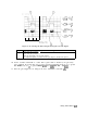
Example of a Time-Gated Pulsed RF Signal
The measurement procedures in this section explain how to use the time gate capability
without the convenience of the Gate Utility functions. The Gate Utility provides the user
with simultaneous displays of the frequency and time domain to assist in setting up and
manipulating the time gate. An oscilloscope is not needed when using the Gate Utility. A list
of all the Gate Utility keys can be found under the
[SWEEP]
key in the key menus in Chapter 8.
Descriptions of the different Gate Utility functions are found in Chapter 7.
Note
This example only applies to using Option 105 with a pulsed RF signal. For
more information on using Option 105 to view other types of signals, see
product note 8590-2 for Option 105.
4-26 Making Measurements