
User`s guide


7. Set the video bandwidth to a value that is greater than 1 divided by the gate length. For
this example, the video bandwidth must be greater than
l/13
~LS,
or 80
kHz.
Press Isw),
VID BW AUTO MAN, 100
(kHz.
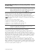
The spectrum analyzer displays only signal 1, not Both signal 1 and signal 2 (see
Figure 4-25).
t
REF
.0
dBm
I
,............
Ami
ATTEN
10
dB
GTPOS
. . . . . . . . . . . . . . . . . . . . . . . . . . . . . . . . . .
LOG
:
I
lilamu
,*,
z/
'1
::,
GATE
LENGTH
GATE DELAY
25 psec
EDGE POL
pDs
NEG
~~o~~~~~::::i_____,
9i;
CENTER
50.i00
"Ii;
SPAN
5.,000
ii;
RRES
BW
100 kHz #UBW 100 kHz #SWP 12~ MS~C
RT
Figure 4-25. Using Time-Gating to View Signal
1
8. To compare signal 1 to signal 2, we first place signal 1 (trace A) in the view mode. Press
(TRACE],
VIEW A, TRACE A B C (so that B is underlined), CLEAR WRITE B .
9. To view the second signal, change the gate delay so that the gate output is under the
second signal. Since the second signal had a signal delay of approximately 85
,q
we set
the gate delay to 85
,M
plus the pulse
width/2,
or 110
p.s.
Press
CSWEEP],
Gate Control ,
GATE DELAY 110
@
to set the gate delay to 110
ps.
Using an oscilloscope can be helpful
in placing the gate output during the pulsed signal (see Figure 4-26).
4-30
Making Measurements