
User`s guide


‘Ihble
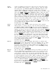
7-12. Preset Spectrum Conditions for All Models
i
t
1
1
1
1
‘
‘
‘
‘
<
f
r
r
7
1
1
1
1
1
7
I
;
:
A-B-A
Analog+ display mode
Annotation and graticule
Attenuation
Center frequency
Center frequency step size
Coupled functions
Coupling *
Detector
Display line
Frequency offset
Harmonic lock
t
Limit-line testing
Scale
Marker counter
$
Marker counter resolution
$
Markers
Measure
3n
end-of-sweep command (ONEOS)
3n-sweep command (ONSWP)
Reference level
Reference level offset
Reference level position
Resolution bandwidth
3pan
3tart
frequency
Stop
frequency
state
registers l-8
sweep
Sweep
time
Threshold
Trace A
Trace
B
Trace C
Trace
math command (TRMATH)
L-ace registers
rrigger
vTideo
averaging
?ideo bandwidth
?ideo bandwidth to resolution bandwidth ratio
’
HP 85943, HP 85953, or HP 85963 only.
Off
Off
on
coupled
Refer to Table
7-10.
10% of span
all set to AUTO
AC
positive peak
Off
0
Hz
Off
off
log 10
dB/div
3ff
2
kHz
(auto-coupled)
Jff
SA
(spectrum analyzer)
cleared
-leared
I
dBm
in power-on units
I
dB
,op
(8th) graticule
3 MHz (coupled)
Refer to Table
7-10.
Refer to Table
7-10.
Refer to Table
7-10.
nraffected
:ontinuous
Refer
to Table
7-10.
(coupled)
)ff
:lear-write
itore-blank
itore-blank
:leared
uraffected
‘ree
)ff
MHz (coupled)
).3
HP
8592L,
HP 85933, HP 85953, or HP 85963 only.
All E-Series and L-Series spectrum analyzers except HP 8590L with Option 713.
7-68 Key Descriptions