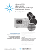
DCA-J Agilent 86100C Wide-Bandwidth Oscilloscope Mainframe and Modules Technical Specifications Four instruments in one A digital communications analyzer, a full featured wide-bandwidth oscilloscope, a time-domain reflectometer, and a jitter analyzer • Accurate compliance testing of optical transceivers • Automated jitter and amplitude interference decomposition • Internally generated pattern trigger • Modular platform for testing waveforms to 40 Gb/s and beyond • Broadest coverage of data rates with opti
Table of Contents Overview of Infiniium DCA-J Features ................................................. 3 Eye diagram mask testing ................................................................ 4 Jitter analysis (Option 200) .............................................................. 5 Advanced EYE Analysis (Option 401) ............................................. 5 Equalization and advanced waveform analysis (Option 201) .... 6 Phase noise/jitter spectrum analysis ...................................
Overview of Infiniium DCA-J Features Four instruments in one The key to accurate measurements of lightwave communications waveforms is the optical receiver. The 86100C has a broad range of precision receivers integrated within the instrument. The 86100C Infiniium DCA-J can be viewed as four high-powered instruments in one: • Built-in photodiodes, with flat frequency responses, yield the highest waveform fidelity. This provides high accuracy for extinction ratio measurements.
Overview of Infiniium DCA-J Features Eye diagram mask testing Eyeline Mode The 86100C provides efficient, high-throughput waveform compliance testing with a suite of standards based eye-diagram masks. The test process has been streamlined into a minimum number of keystrokes for testing at industry standard data rates. Eyeline Mode is available in the 86100C and provides insight into the effects of specific bit transitions within a data pattern.
Overview of Infiniium DCA-J Features Jitter analysis (Option 200) Advanced EYE Analysis (Option 401) The “J” in DCA-J represents the ability to perform jitter analysis. The 86100C is a Digital Communications Analyzer with jitter analysis capability. The 86100C adds a fourth mode of operation – Jitter Mode. Extremely wide bandwidth, low intrinsic jitter, and advanced analysis algorithms yield the highest accuracy in jitter measurements.
Overview of Infiniium DCA-J Features Equalization and advanced waveform analysis (Option 201) Advanced amplitude analysis/RIN/Q-factor (Option 300) In addition to jitter, signal quality can also be impacted by impairments in the amplitude domain. Similar to the many types of jitter that exist, noise, inter-symbol interference, and periodic fluctuation can cause eye closure in the amplitude domain.
Overview of Infiniium DCA-J Features Phase noise/jitter spectrum analysis the stimulus as well as the DUT response. By sweeping the frequency of the jitter stimulus, the ratio of the output jitter to the input jitter provides the PLL bandwidth. The measurement system is extremely flexible and can test input/outputs from 50 Mb/s to 14.2 Gb/s (data signals) and/or 25 MHz to 6.75 GHz (clock signals).
Measurements Option 201 advanced waveform analysis The following measurements are available from the tool bar, as well as the pull down menus. The available measurements depend on the DCA-J operating mode.
Additional capabilities Standard functions • Jitter Mode ◦◦ Units (time or unit interval, watts, volts, or unit amplitude) Standard functions are available through pull down menus and soft keys, and some functions are also accessible through the front panel knobs.
Additional capabilities Built-in information system The 86100C has a context-sensitive on-line manual providing immediate answers to your questions about using the instrument. Links on the measurement screen take you directly to the information you need including algorithms for all of the measurements. The on-line manual includes technical specifications of the mainframe and plug-in modules.
Additional capabilities Waveform autoscaling Transitioning from the Agilent 83480A and 86100A/B to the 86100C Autoscaling provides quick horizontal and vertical scaling of both pulse and eye-diagram (RZ and NRZ) waveforms. While the 86100C has powerful new functionality that its predecessors don’t have, it has been designed to maintain compatibility with the Agilent 86100A, 86100B and Agilent 83480A digital communications analyzers and Agilent 54750A wide-bandwidth oscilloscope.
Additional capabilities Lowest intrinsic jitter Accurate views of your 40 Gb/s waveforms The industry standard for lowest oscilloscope jitter was set with the development of the 86107A precision timebase reference module. Mainframe jitter is reduced to levels below 200 fs. Low oscilloscope jitter allows the true jitter performance of devices to be seen. Oscilloscope jitter can be driven to even lower levels when using the 86108A precision waveform analyzer.
Specifications General and Mainframe Specifications describe warranted performance over the temperature range of +10 °C to +40 °C (unless otherwise noted). The specifications are applicable for the temperature after the instrument is turned on for one (1) hour, and while self-calibration is valid. Many performance parameters are enhanced through frequent, simple user calibrations. Characteristics provide useful, non-warranted information about the functions and performance of the instrument.
Specifications General and Mainframe Mainframe specifications (continued) Standard (direct trigger) Trigger modes Internal trigger1 External direct trigger2 Limited bandwidth3 Full bandwidth External divided trigger PatternLock Jitter Characteristic Maximum Trigger sensitivity Trigger configuration Trigger level adjustment Edge select Hysteresis5 Trigger gating Gating input levels (TTL compatible) Gating delay Trigger impedance Nominal impedance Reflection Connector type Maximum trigger signal Option
Specifications Precision Time Base Module Precision time base 86107A1 86107A Option 010 86107A Option 020 86107A Option 040 Trigger bandwidth 2.0 to 15.0 GHz 2.4 to 25.0 GHz 2.4 to 48.0 GHz Typical jitter (RMS) 2.0 to 4.0 GHz trigger: < 280 fs 4.0 to 15.0 GHz trigger: < 200 fs 2.4 to 4.0 GHz < 280 fs 4.0 to 25.0 GHz < 200 fs 2.4 to 4.0 GHz < 280 fs 4.0 to 48.0 GHz < 200 fs Time base linearity error < 200 fs Input signal type Synchronous clock2 Input signal level 0.5 to 1.0 Vpp 0.2 to 1.
Specifications Computer System and Storage Computer system and storage CPU Mass storage 1 GHz microprocessor 40 GByte internal hard drive Operating system Microsoft Windows XP Pro Display 1 Display area Active display area Waveform viewing area Entire display resolution Graticule display resolution Waveform colors Persistence modes Waveform overlap Connect-the-dots Persistence Graticule Grid intensity Backlight saver Dialog boxes 170.9 mm x 128.2 mm (8.
Modules Overview Optical/electrical modules The 86108A has two electrical channels with over 32 GHz (typically 35 GHz) of bandwidth. Clock recovery (similar to the 83496B) and a precision timebase (similar to the 86107A) are integrated into the module to provide the highest precision electrical waveform measurements. Residual jitter can be < 60 fs and trigger to sample delay is effectively < 200 ps.
Modules Selection Table 86100 family plug-in module matrix Electrical bandwidth (GHz) Fiber input (μm) Mask test sensitivity (dBm) 1 1 750-1650 8.5 20 62.5 -20 200 1 1 750-1650 8.5 20 62.5 -16 3002 1 1 750-1650 8.5 20 62.5 -16 1 1 750-1650 20 35 62.5 -12 86105D3 86115D 3 Filtered data rates 155 Mb/s 622 Mb/s 1063 Mb/s 1244/1250 Mb/s 2125 Mb/s 2488/2500 Mb/s 2.666 Gb/s 3.125 Gb/s 4.25 Gb/s 5.00 Gb/s 6.25 Gb/s 8.50 Gb/s 9.953 Gb/s 10.3125 Gb/s 10.51875 Gb/s 10.664 Gb/s 10.
Modules Specifications Single-mode and Multimode Optical/Electrical Multiple and single-mode optical/electrical modules 86105C Optical channel specifications Optical channel unfiltered bandwidth Wavelength range Calibrated wavelengths Optical sensitivity1 Transition time (10% to 90% calculated from TR = 0.48/BW optical) RMS noise Characteristic Maximum Scale factor (per division) 86105D 86115D Option 002 86115D Option 004 8.
Modules Specifications Single-mode and Multimode Optical/Electrical Multiple and single-mode optical/electrical modules 86105C Optical channel specifications (continued) 86105D 86115D Option 002 86115D Option 004 Average power monitor accuracy Single-mode ±5% ±200 nW ±connector uncertainty ± 5%±200 nW ±connector uncertainty ±5% ±100 nW ±connector uncertainty (20 to 30 °C) ± 5%±200 nW ±connector uncertainty Multimode (characteristic) ±10% ±200 nW ±connector uncertainty ± 5% ±200 nW ±connector unce
Modules Specifications Single-mode Optical/Electrical High bandwidth single-mode optical/electrical modules 86116C1 Option 025 Optical channel unfiltered bandwidth 45 GHz Wavelength range 1300n m to 1620 nm Optical channel specifications Calibrated wavelengths Optical sensitivity 86116C1 Option 041 65 GHz 4 1310 nm/1550 nm 1310 nm –9 dBm (17 Gb/s) –8 dBm (25.8 Gb/s) –7 dBm (27.7 Gb/s) –3 dBm (39.8/43.0 Gb/s 1550 nm –10 dBm (17 Gb/s) –9 dBm (25.8 Gb/s) –8 dBm (27.7 Gb/s) –5 dBm (39.8/43.
Modules Specifications Single-mode Optical/Electrical High bandwidth single-mode optical/electrical modules Optical channel specifications (continued) 86116C1 Scale factor Minimum 200 μW/division Maximum 5 mW/division CW2 accuracy (single marker, reference to average power monitor) ± 150 µW ± 4% (reading-channel offset) CW offset range (referenced two divisions from screen button) +8 to –12mW Average power monitor (specified operating range) –23 to +9 dBm Factory calibrated accuracy User calibr
Modules Specifications Dual Electrical Dual electrical channel modules 86112A 54754A Electrical channel bandwidth Transition time (10% to 90% calculated from TR = 0.35/BW) 12.4 and 20 GHz 28.2 ps (12.4 GHz) 17.5 ps (20 GHz) 12.4 and 18 GHz 28.2 ps (12.4 GHz) 19.4 ps (18 GHz) Characteristic 0.25 mV (12.4 GHz) 0.5 mV (20 GHz) 0.5 mv (12.4 GHz) 1 mV (20 GHz) 0.25 mV (12.4 GHz) 0.5 mV (18 GHz) 0.5 mv (12.
Modules Specifications Dual Electrical Dual electrical channel modules Bandwidth Transition time (10% to 90% calculated from Tr = 0.
Modules Specifications TDR System TDR system (Mainframe with 54754A module) Oscilloscope/TDR performance Normalized characteristics Rise time 40 ps nominal < 25 ps normalized Adjustable from larger of 10 ps or 0.08 x time/div Maximum: 5 x time/div TDR step flatness ≤ ±1% after 1 ns from edge ≤ ±5%, –3% < 1 ns from edge ≤ 0.1% Low level High level 0.
Modules Specifications TDR System 86100C Option 202 characteristics Return loss Attenuation Attenuation uncertainty – phase 6 dB 30 20 6 dB 20 10 12 dB 10 Degrees Degrees Return loss uncertainty – phase 30 12 dB 0 20 dB 20 dB 20 dB 30 dB 30 dB 20 dB –10 –20 26 dB –20 –30 3 6 9 GHz 12 –30 16 12 dB 12 dB 0 –10 26 dB 6 dB 6 dB 40 dB 40 dB 3 6 9 GHz 12 16 *See end notes for additional phase uncertainties *See end notes for additional phase uncertainties Performance chara
Modules Specifications 83496B-100 83496B-101 Channel type Differential or single-ended electrical Single-mode or multimode optical, differential or single-ended electrical (no internal electrical splitters) Data rates (divide by 2 for clock signals) Standard: 50 Mb/s to 7.1 Gb/s continuous tuning Option 200: 50 Mb/s (14.2 Gb/s for 83496B with firmware revision 8.1 or higher) Option 201: 7.1 to 14.
Modules Specifications Electrical through-path digital amplitude attenuation5 83496B-100 83496B-101 7.5 dB (No electrical data output signal path) Wavelength range 830-860 nm and 1260-1360 nm multimode 1260-1360 nm and 1490-1600 nm single mode Electrical: 150 m Vpp Front panel recovered clock output amplitude 1 Vpp max, 220 mVpp min, 300 mVpp Consecutive identical digits (CID) 150 max Front panel recovered clock output N=1 to 16 @ data rates 50 Mb/s to 7.1 Gb/s N=2 to 16 @ data rates 7.
Ordering Information 86100C Infiniium DCA-J mainframe 86100C-001 Enhanced trigger 86100CS-001 Enhanced trigger upgrade kit 86100C-061 MATLAB - Basic Oscilloscope Package 86100C-062 MATLAB - Standard Oscilloscope Package 86100C-701 Standard trigger (default) 86100C-090 Removable hard drive 86100C-092 Internal hard drive (default) 86100C-200 Jitter analysis software 86100CU-200 Enhanced Jitter analysis software upgrade 86100C-201 Advanced waveform analysis software 86100CU-201 Advanced waveform analysis softw
Ordering Information Dual electrical channel modules 86108A-002 86108A-003 86108A-006 86108A-010 86108A-020 86112A Dual 20 GHz electrical channels 86117A Dual 50 GHz electrical channels 86118A Dual 70 GHz electrical remote sampling channels 86118A-H01 Differential De-Skew TDR/TDT modules Included with each of these TDR modules is a TDR trigger cable, two 50 Ω SMA terminations and one SMA short.
Ordering Information Passive probe Infiniimax II active probes (10 to 13 GHz) 54006A Note: The N1022B probe adapter is required to use these probes with the 86100 DCA 6 GHz passive probe Infiniimax I active probes (1.5 to 7 GHz) Infiniimax I probe amplifiers Note: Order one or more Infiniimax I probe head or connectivity kit for each amplifier Infiniimax II probe amplifiers Note: Order 1 or more Infiniimax II probe heads for each amplifier.
www.agilent.com www.agilent.com/find/dcaj myAgilent myAgilent www.agilent.com/find/myagilent A personalized view into the information most relevant to you. www.axiestandard.org AdvancedTCA® Extensions for Instrumentation and Test (AXIe) is an open standard that extends the AdvancedTCA for general purpose and semiconductor test. Agilent is a founding member of the AXIe consortium. Three-Year Warranty www.agilent.