
Specifications


22
Modules Specifications
Single-mode Optical/Electrical
High bandwidth single-mode
optical/electrical modules 86116C
1
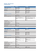
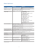
Optical channel specifications (continued)
Scale factor
Minimum 200 μW/division
Maximum 5 mW/division
CW
2
accuracy (single marker,
reference to average power monitor)
± 150 µW ± 4%
(reading-channel offset)
CW offset range (referenced two
divisions from screen button)
+8 to –12mW
Average power monitor
(specified operating range)
–23 to +9 dBm
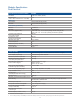
Factory calibrated accuracy
User calibrated accuracy
±5% ±100 nW ±connector uncertainty, 20 to 30 °C
±2% ±100 nW ±power meter uncertainty, < 5 °C change
Maximum input power
Maximum non-destruct average 10 mW (+10 dBm)
Maximum non-destruct peak 50 mW (+17 dBm)
Fiber input 9/125 μm, user-selectable connector
Input return loss
(HMS-10 connector fully filled fiber)
20 dB
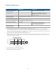
Electrical channel specifications
Electrical channel bandwidth
80 (93), 55 and 30 GHz
Transition time (10% to 90%
calculated from Tr = 0.35/BW )
6.4 ps (55 GHz)
4.4 ps (80 GHz)
RMS noise
Characteristic 0.5 mV (30 GHz)
0.6 mV (55 GHz)
1.1 mV (80 GHz)
Maximum 0.8 mV (30 GHz)
1.1 mV (55 GHz)
2.2 mV (80 GHz)
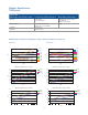
Scale factor
Minimum 2 mV/division
Maximum 100 mV/division
DC accuracy (single marker) ±0.4% of full scale
±3 mV ±2% of (reading-channel offset), ±2% of offset (all bandwidths)
DC offset range
(referenced to center of screen)
±500 mV
Input dynamic range
(relative to channel offset)
±400 mV
Maximum input signal ± 2 V (+16 dBm)
Nominal impedance 50 Ω
Reflections (for 20 ps rise time) 10% (DC to 70 GHz)
20% (70 to 100 GHz)
Electrical input 1.85 mm (male)
1. 86116C requires an 86100C mainframe and software revision 7.0 or above.
2. CW refers to an unmodulated optical signal.