
Specifications

13
Basic Oscilloscope Controls and Measurements (continued)
Basic front-panel controls
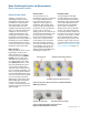
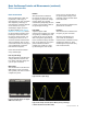
Pulse-width triggering – Pulse
width triggering is similar to
glitch triggering when you are
looking for specific pulse widths.
However, it is more general in
that you can trigger on pulses of
any specified width and you can
choose the polarity (negative or
positive) of the pulses you want
to trigger on. You can also set
the horizontal position of the
trigger. This allows you to see
what occurred pre-trigger or
post-trigger. For instance, you
can execute a glitch trigger, find
the error, and then look at the
signal pre-trigger to see what
caused the glitch. If you have the
horizontal delay set to zero, your
trigger event will be placed in the
middle of the screen horizontally.
Events that occur right before
the trigger will be to the left of
the screen and events that occur
directly after the trigger will be
to the right of the screen. You
also can set the coupling of the
trigger and set the input source
you want to trigger on. You do not
always have to trigger on your
signal, but can instead trigger on
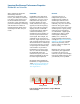
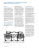
a related signal. Figure 20 shows
the trigger control section of an
oscilloscope’s front panel.
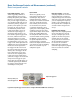
Input controls
There are typically two or
four analog channels on an
oscilloscope. They will be
numbered and they will also
usually have a button associated
with each particular channel
that enables you to turn them
on or off. There may also be
a selection that allows you to
specify AC or DC coupling. If DC
coupling is selected, the entire
signal will be input. On the other
hand, AC coupling blocks the
DC component and centers the
waveform about 0 volts (ground).
In addition, you can specify
the probe impedance for each
channel through a selection
button. The input controls also let
you choose the type of sampling.
There are two basic ways to
sample the signal:
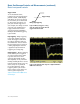
Real-time sampling – Real-time
sampling samples the waveform
often enough that it captures a
complete image of the waveform
with each sweep. This is useful if
you are sampling low-frequency
signals, as the oscilloscope has
the required time to sample the
waveform often enough in one
sweep.
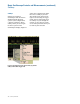
Equivalent-time sampling –
Equivalent time sampling builds
up the waveform over several
sweeps. It samples part of the
signal on the first sweep, then
another part on the second
sweep, and so on. It then laces
all this information together
to recreate the waveform.
Equivalent time sampling is
useful for high-frequency signals
that are too fast for real-time
sampling.
Figure 20. Front panel trigger control section on an Agilent InfiniiVision 5000 Series oscilloscope
Adjusts the trigger level
These keys allow you to
select the trigger mode
Oscilloscope Fundamentals