Infiniium DCA-J Agilent 86100C Wide-Bandwidth Oscilloscope Quick Start Guide Agilent Technologies
Notices Technology Licenses Trademark Acknowledgements © Agilent Technologies, Inc. 2000-2007 The hardware and/or software described in this document are furnished under a license and may be used or copied only in accordance with the terms of such license. Microsoft is a U.S. registered trademark of Microsoft Corporation.
Contents 1 Installing the 86100C Installing the 86100C 1–2 Connector Care 1–37 Returning the Instrument for Service 1–42 2 Using the 86100C A Quick Tour 2–2 Eye/Mask Mode 2–8 Jitter/Amplitude Analysis Mode 2–11 Oscilloscope Mode 2–13 TDR/TDT Mode 2–14 Quick Measure 2–15 Optional Features and Licenses 2–16 Windows XP Professional 2–19 If the Infiniium DCA has a Problem 2–22 3 Using the Built-In Information System Using the Built-In Information System 3–2 Getting Help While Changing Instrument Settings 3–4 L
Contents Contents-2
1 Installing the 86100C 1-2 Step 1. Inspect the shipment 1-5 Step 2. Position the Infiniium DCA 1-7 Step 3. Install the modules 1-8 Step 4. Connect the keyboard and mouse 1-9 Step 5. Connect a printer (Optional) 1-10 Step 6. Connect the power 1-11 Step 7. Windows Setup Wizard 1-14 Step 8. Change removable hard disk (Option 86100C-090) Step 9. Install a feature license (Optional) 1-19 Step 10. Calibrate the touch screen 1-22 Step 11. Avoid costly repairs 1-24 Step 12.
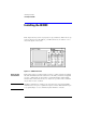
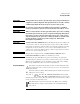
Installing the 86100C Installing the 86100C Installing the 86100C This chapter shows you how to properly set up your 86100C. Follow the steps in the order presented. In addition, you will learn about care and use of electrical and optical connections. Figure 1-1. 86100C Front Panel General Safety Considerations This product has been designed and tested in accordance with the standards listed in the Manufacturer’s Declaration of Conformity, and has been supplied in a safe condition.
Installing the 86100C Installing the 86100C WARNING If this product is not used as specified, the protection provided by the equipment could be impaired. This product must be used in a normal condition (in which all means for protection are intact) only. WARNING No operator serviceable parts inside. Refer servicing to qualified service personnel. To prevent electrical shock do not remove covers.
Installing the 86100C Installing the 86100C The C-Tick mark is a registered trademark of the Australian Spectrum Management Agency. This product complies with the WEEE Directive (2002/96/EC) marking requirements. The affixed label indicates that you must not discard this electrical/electronic product in domestic household waste. Product Category: With reference to the equipment types in the WEEE Directive Annex I, this product is classed as a “Monitoring and Control instrumentation” product.
Installing the 86100C Step 1. Inspect the shipment Step 1. Inspect the shipment ❒ Inspect the shipping container and instrument for damage. Keep the shipping container and cushioning material until you have inspected the contents of the shipment for completeness and have checked the instrument mechanically and electrically. ❒ Locate the shipping list. Verify that you received all the accessories on this list, and all the options that you ordered.
Installing the 86100C Step 1. Inspect the shipment adapters is easy. Simply hand turn an adapter counter-clockwise to remove it from a channel connector; to install a different adapter, hand turn the new adapter clockwise onto the connector. Table 1-1. Fiber-Optic Adapters for Optical Channels Front Panel Fiber-Optic Adapters Instrument Options Description Agilent Part Number Diamond HMS-10 81000AI FC/PC 81000FI SC 81000KI DIN 81000SI ST 81000VI • 86100C-001, Enhanced 12.
Installing the 86100C Step 2. Position the Infiniium DCA Step 2. Position the Infiniium DCA Position the Infiniium DCA so that it will have sufficient clearance for airflow around the top, back, and sides. Review the following specifications to ensure that your operating or storage environment is suitable for the instrument. NOTE Install the instrument so that the detachable power cord is readily identifiable and is easily reached by the operator.
Installing the 86100C Step 3. Install the modules Step 3. Install the modules Up to two modules can be inserted into the Infiniium DCA. All documentation (including specifications) for plug-in modules is located in the 86100C’s Help system. To access the Help system, complete the installation steps, turn on the 86100C, and click Contents on the Help menu. 1 Slide the module into an available front-panel slot. You can remove or install a module while the instrument is operating.
Installing the 86100C Step 4. Connect the keyboard and mouse Step 4. Connect the keyboard and mouse NOTE To complete the installation, you must connect the keyboard to the 86100C. Since the 86100C has a touch screen, the use of a mouse is optional. 1 Connect the supplied USB keyboard to either of two USB ports located on the rear panel. Most users find it more convenient to connect the keyboard to the rear-panel leaving the front-panel USB port available for a USB flash drive.
Installing the 86100C Step 5. Connect a printer (Optional) Step 5. Connect a printer (Optional) Perform this step if you plan to connect a printer directly to the serial, parallel, or USB ports that are located on the 86100C rear panel. If you have a parallel (Centronics) printer, you will need a parallel printer cable, such as an C2950A (2 m) or C2951A (3 m) cable. If you have a serial printer, you will need a 9-pin to 25-pin serial printer cable, such as an 34398A cable, plus the 34399A adapter kit.
Installing the 86100C Step 6. Connect the power Step 6. Connect the power CAUTION Always use the three-prong AC power cord supplied with this instrument. Failure to ensure adequate earth grounding by not using this cord may cause product damage. CAUTION Do not connect ac power until you have verified the line voltage is correct as described in Table 1-2 on page 1-7. Damage to the equipment could result. • Connect the line cord as shown in the figure below. Figure 1-5.
Installing the 86100C Step 6. Connect the power CAUTION This instrument has autoranging line voltage input. Be sure the supply voltage is within the specified range. CAUTION Windows XP registry: If the Infiniium DCA is mounted in a rack or cabinet, do not use the system power switch to disconnect power from the instrument. Instead, use the Infiniium DCA front-panel power switch.
Installing the 86100C Step 6. Connect the power Table 1-3. Available Line Cords Plug Type Cable Part No.
Installing the 86100C Step 7. Windows Setup Wizard Step 7. Windows Setup Wizard This step requires several minutes to prepare Windows XP using the Windows XP Setup Wizard. During the following steps, you will be instructed to “click” with the pointing device. You can use a mouse (if you connected it) or you can touch the screen with your finger. CAUTION Before switching on this instrument, make sure the supply voltage is in the specified range.
Installing the 86100C Step 7. Windows Setup Wizard Figure 1-7. Windows XP Setup Wizard 3 Click Next to display the License Agreement. Figure 1-8. Windows XP License Agreement 4 Select I accept this agreement and then click Next.
Installing the 86100C Step 7. Windows Setup Wizard 5 Enter your name and the name of your organization or company. Click Next. Figure 1-9. Personal Information Setup 6 Click Next. 7 Adjust the date, time, and time zone as needed in the displayed screen. Check automatic clock adjust for daylight saving changes, if it applies to your location. Figure 1-10.
Installing the 86100C Step 7. Windows Setup Wizard 8 Click Next. The setup will take a few moments to complete and to automatically restart the instrument. In about one or two minutes, you should see the 86100C screen screen, as shown in the following figure. Figure 1-11. The 86100C Display CAUTION To ensure proper operation of the 86100C, read “Avoid changing these Windows system settings” on page 2-21.
Installing the 86100C Step 8. Change removable hard disk (Option 86100C-090) Step 8. Change removable hard disk (Option 86100C-090) If your instrument includes Option 86100C-090, you must repeat the Windows XP Setup Wizard procedure for the second, identical hard disk. The removable hard disk option, 86100C-090, is designed for 86100C instruments that are used in a secure environment. For more information, refer to “To use the removable hard disk option” on page 1-30. 1 Turn off the 86100C.
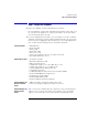
Installing the 86100C Step 9. Install a feature license (Optional) Step 9. Install a feature license (Optional) If you ordered an optional feature, such as Option 200 Enhanced Jitter Analysis, with your 86100C, it was probably installed at the factory. If you ordered it, but it wasn’t installed, you received a Software Entitlement Certificate that you must use to install the license on your 86100C. To confirm if your license was installed 1 On the 86100C Utilities menu, click Licenses.
Installing the 86100C Step 9. Install a feature license (Optional) To install a license 1 On the 86100C Utilities menu, click Licenses. Write down the HostID and Serial # identifiers listed on the displayed dialog box. You will need this information in the next step. 2 Go to the following web site to obtain your license file. You will need to enter the HostID and Serial # identifiers for your 86100C. The license file will be sent to you via email. www.agilent.
Installing the 86100C Step 9. Install a feature license (Optional) as shown in the following picture. In the Install New License dialog box, click Enter 60 Digit Key Code and enter your key code. The letters in the key code are not case sensitive, so you can enter letters in either upper or lower case. Figure 1-14. Example of the contents of a license file . Figure 1-15.
Installing the 86100C Step 10. Calibrate the touch screen Step 10. Calibrate the touch screen The touch screen configuration utility aligns and orientates the touch screen with the display so that when you touch an element on the display screen, the instrument can detect the task that you want to perform. The display will always function as a touch screen, even when a mouse and keyboard are connected. 1 On the Utilities menu, choose Touch Screen Config.
Installing the 86100C Step 10. Calibrate the touch screen Figure 1-17.
Installing the 86100C Step 11. Avoid costly repairs Step 11. Avoid costly repairs Figure 1-18. Avoid Costly Repairs • Refer to the “Connector Care” on page 1-37, before making any electrical or optical input connections. CAUTION Electrical channel input circuits and the trigger input circuit can be damaged by electrostatic discharge (ESD). Therefore, avoid applying static discharges to the front-panel input connectors.
Installing the 86100C Step 12. Calibrate the modules Step 12. Calibrate the modules This is the last step required for installing the 86100C and preparing it for use. Additional procedures in this section are provided, if needed. To learn about using your 86100C, be sure to read Chapter 2, “Using the 86100C” and the instrument’s built-in Help system. A module calibration establishes calibration factors for all installed modules.
Installing the 86100C Step 12. Calibrate the modules 2 Touch the Modules tab. The Modules tab opens and allows you to perform a module calibration on either the left or right module. 3 Touch the Calibrate Module button (located at the bottom of the tab) for the module you need to calibrate. This starts the module calibration. Figure 1-19. Calibrate Module Button 4 Remove all external devices and signals from the module. The module calibration uses known signal levels in the instrument.
Installing the 86100C Step 12. Calibrate the modules Figure 1-20. Calibration Progress 6 After the calibration completes, choose All Calibrations on the Calibration menu. 7 The Modules tab shows the status of the calibration and should indicate that the “Current user module calibration is valid.
Installing the 86100C To configure a LAN connection To configure a LAN connection You can configure the 86100C on a LAN for file sharing and using network printers. If you do not know how to set up a network, contact your network administrator or use the Windows XP Professional on-line help. The network setup is different for every company. Your company’s network administrator can set up your instrument with the appropriate client, protocol, and configuration for your local area network (LAN).
Installing the 86100C To configure a LAN connection 4 Click Start to view the Windows Start Menu. Figure 1-22. Windows Start Menu 5 Click My Computer to set up a network connection, map a network drive, or share an 86100C folder. You can share any folder on the USER (D:) drive. Click Help and Support to get detailed information.
Installing the 86100C To use the removable hard disk option To use the removable hard disk option The removable hard disk option, 86100C-090, is designed for 86100C instruments that are used in a secure environment. Because the hard disk is easily removed from the instrument, you can protect any sensitive data. The following two procedures are provided in this section: To declassify instrument memory 1-30 To exchange the removable hard disks 1-32 The removable hard disk option comes with two hard disks.
Installing the 86100C To use the removable hard disk option b On the Setup menu, click Acquisition to open the Acquisition dialog box. c On the Waveform tab, click Manual and enter a value of 4096. d Close the Acquisition dialog box. e On Option 001 instruments, click the Pattern Lock button shown in Figure 1-23. When the Pattern Autodetect Fail dialog box is displayed, click Cancel to close the dialog box. Pattern Lock Figure 1-23.
Installing the 86100C To use the removable hard disk option To exchange the removable hard disks If you are removing the 86100C from a secure area, perform the procedure “To declassify instrument memory” on page 1-30 before starting the following steps. 1 Turn the 86100C on. 2 If the instrument has been returned from Agilent with a new mainframe calibration, you must save a copy of the calibration file from the current hard disk. Later in this procedure, you will install this file on the secure hard disk.
Installing the 86100C To use the removable hard disk option d From the Windows Start menu, click My Computer. e Enter the path, c:\scope\cal, in the address line as shown in Figure 1-25 on page 33. Then, press Enter to locate the file, framecal.dat. NOTE The folder, c:\scope\cal, is hidden and will not be shown if you browse for it. f Copy the file, framecal.dat, to an external USB memory device. 3 Turn off the 86100C.
Installing the 86100C To use the removable hard disk option 9 If you saved the mainframe calibration file in Step 2, perform these steps: a Turn on the 86100C, and click Exit on the File menu to close the DCA application. b From the Windows Start menu, click My Computer. c Locate the file, framecal.dat, that you copied to your external USB memory device. d Copy this file and paste the file into the folder, c:\scope\cal.
Installing the 86100C To connect an external display To connect an external display You can connect a VGA-compatible display to the 86100C to provide a larger viewing area of the screen. 1 Connect the display cable to the rear-panel VGA connector. This connector is labeled External Display on Figure 1-26. 2 Tighten the retaining screws. 3 Connect the external display. The rear-panel VGA connector labeled Second Desktop Connection on Figure 1-26 is provided for use of the Windows second desktop feature.
Installing the 86100C To clean the 86100C To clean the 86100C Clean the 86100C using a soft cloth slightly dampened with a mild soap and water solution. WARNING To prevent electrical shock, disconnect the Agilent Technologies model 86100C from mains before cleaning. Use a dry cloth or one slightly dampened with water to clean the external case parts. Do not attempt to clean internally. CAUTION Do not use too much liquid in cleaning the oscilloscope.
Installing the 86100C Connector Care Connector Care Damage to 86100C electrical and fiber-optic input connectors (as well as connectors on calibration and verification devices, test ports, cables, and other devices) can degrade measurement accuracy and damage instruments. Replacing a damaged electrical and fiber-optic connectors can cost thousands of dollars, not to mention lost time! This expense can be avoided by observing some important precautions.
Installing the 86100C Electrical Connections Electrical Connections WARNING If flammable fluids are used to clean connectors, the fluid shall not be placed on the instrument during, use or when connected to mains voltage. Cleaning the connectors shall take place in ventilated area to allow fluid vapors to dissipate, and reduce the risk of fire. CAUTION The input circuits can be damaged by electrostatic discharge (ESD).
Installing the 86100C Electrical Connections • • • • • • Make preliminary connection lightly To tighten, turn connector nut only Do not apply bending force to connection Do not over tighten preliminary connection Do not twist or screw in connectors Do not tighten past the "break" point of the torque wrench Using Connector Savers Connector savers are useful in prolonging instrument life and ensuring better quality measurements. Refer to the online help for a list of commonly used connector savers. 3.
Installing the 86100C Fiber-Optic Connections • Make a gentle, preliminary connection. If initial alignment is correct the connector nut should thread on to the female outer conductor with minimal friction. • If friction is encountered, STOP! Disassemble the connector immediately and determine the cause of the problem. Failure to observe this caution will lead to almost certain damage to one or both of the connectors. • When you make a connection, turn only the connector nut.
Installing the 86100C Fiber-Optic Connections misalignment and excessive return loss. Many measurements are actually improved by backing off the connector pressure. Also, if a piece of grit does happen to get by the cleaning procedure, the tighter connection is more likely to damage the glass. Tighten the connectors just until the two fibers touch. • Keep connectors covered when not in use. • Use fusion splices on the more permanent critical nodes. Choose the best connector possible.
Installing the 86100C Returning the Instrument for Service Returning the Instrument for Service The instructions in this section show you how to properly package the instrument for return to an Agilent Technologies service office. If the instrument is still under warranty or is covered by an Agilent maintenance contract, it will be repaired under the terms of the warranty or contract.
Installing the 86100C Preparing the instrument for shipping Preparing the instrument for shipping 1 Write a complete description of the failure and attach it to the instrument. Include any specific performance details related to the problem. The following information should be returned with the instrument. • Type of service required. • Date instrument was returned for repair. • Description of the problem: • Whether problem is either constant or intermittent. • Whether instrument is temperature-sensitive.
Installing the 86100C Preparing the instrument for shipping all sides of the instrument for packing material, and strong enough to accommodate the weight of the instrument. • Surround the equipment with approximately 7 cm (3 inches) of packing material, to protect the instrument and prevent it from moving in the carton. If packing foam is not available, the best alternative is S.D-240 Air Cap™ from Sealed Air Corporation (Commerce, California 90001).
2 A Quick Tour 2-2 Eye/Mask Mode 2-8 To View an Eye Diagram 2-9 Jitter/Amplitude Analysis Mode 2-11 To measure jitter 2-12 Oscilloscope Mode 2-13 TDR/TDT Mode 2-14 Quick Measure 2-15 Optional Features and Licenses 2-16 Option 200, Enhanced Jitter Analysis 2-17 Option 201, Advanced Waveform Analysis 2-18 Option 202, Enhanced Impedance and S-Parameter 2-18 Option 300, Advanced Amplitude Analysis/RIN/Q-factor 2-17 Windows XP Professional 2-19 Avoid changing these Windows system settings 2-21 If the Infiniium D
Using the 86100C A Quick Tour A Quick Tour The Infiniium DCA measures a variety of high speed digital communication waveforms in any of four instrument modes: • Eye/Mask Mode for eye diagram analysis and standards testing (for example, SONET/SDH, Gigabit Ethernet, and Fiber Channel). • Jitter/Amplitude Analysis Mode. Requires Option 001 Enhanced Trigger and Option 200. Also requires Option 300, if Amplitude Analysis is desired. Licenses can be purchased after the initial instrument purchase.
Using the 86100C A Quick Tour Use the touch screen You can explore the instrument’s menus and change its settings by touching the display, clicking a mouse, or using front-panel knobs and buttons. The following picture shows the display with the optional Enhanced Jitters Analysis and Advanced Amplitude Analysis/RIN/Q-Factor software. Figure 2-2.
Using the 86100C A Quick Tour You must provide a trigger input signal Because high-speed oscilloscopes are not capable of triggering directly on a test signal, you must first connect an external timing reference signal to the front-panel Trigger input connector. This input allows the Infiniium DCA to synchonize to the input signal. Clock recovery modules (for example, the 83496B) are available to recover the clock from the test signal.
Using the 86100C A Quick Tour To learn more about your Infiniium DCA • Refer to the online Help, which contains information that would normally be in the user’s guide • Visit our website at http://www.agilent.com. Use the keywords “Infiniium DCA” or “86100C” in your search. Figure 2-4.
Using the 86100C A Quick Tour Plug-in Modules The Infiniium DCA holds up to two plug-in modules, which can provide up to four measurement channels. Each input channel has its own vertical controls. The amplitude scale knob adjusts the amplitude scale used for the input channel. Use the amplitude offset knob to position the displayed signal. You can also set the amplitude scale and offset to specific values by touching of channel buttons shown to at the bottom of the display.
Using the 86100C A Quick Tour CAUTION Optical channel fiber-optic connectors are easily damaged when connected to dirty or damaged cables and accessories. When you use improper cleaning and handling techniques, you risk expensive instrument repairs, damaged cables, and compromised measurements. Before you connect any fiber-optic cable to the digital communications analyzer, refer to “Connector Care” on page 1-37.
Using the 86100C Eye/Mask Mode Eye/Mask Mode Eye/Mask mode allows you to perform NRZ (Non-Return to Zero), or RZ (Return to Zero) eye diagram measurements and eye mask tests. The eye diagram is typically produced by triggering the instrument with a synchronous clock signal. Eye/Mask mode measurements only work when an eye diagram, and not a pulse, is present on the screen. Measurements made on a pulse waveform while in Eye/Mask mode will fail.
Using the 86100C Eye/Mask Mode To View an Eye Diagram When learning to use the instrument, practice viewing a PRBS signal, which will have a varied number of ones and zeros and will produce a classic eye diagram. NOTE The 86100C Help contains many more measurement procedures for Eye/Mask mode. 1 Select a DCA module that is compatible with the type of signal that you are measuring. 2 Install the module into the DCA mainframe. You don't have to turn the mainframe off before installing the module.
Using the 86100C Eye/Mask Mode 8 On the display, click the Trigger button to open the Trigger dialog box. Or, on the Setup menu, click the Trigger. Select the General Trigger Setup tab on the dialog box. 9 Locate the Bandwidth settings in the Trigger dialog box. Select Standard for data rates up to 3.2 GHz. This is the default bandwidth setting. If the instrument has the enhanced trigger installed (Option 001), select Divided for direct or divided trigger rates between 2 GHz and 13 GHz.
Using the 86100C Jitter/Amplitude Analysis Mode Jitter/Amplitude Analysis Mode Jitter Mode is an optional feature that, if installed, adds powerful jitter (time and frequency domain) measurement capability to the Infiniium DCA. Refer to “Optional Features and Licenses” on page 2-16 for information on adding this option. Jitter Mode can be extended to the amplitude domain by installing the additional Option 300 software. Refer to “Option 300, Advanced Amplitude Analysis/RIN/Q-factor” on page 2-17.
Using the 86100C Jitter/Amplitude Analysis Mode To measure jitter NOTE The 86100C Help contains more measurement procedures for Jitter mode. 1 Connect the data signal to a module's front-panel channel input connector, and press the associated channel button. The channel button will be lit when a channel is selected. Turn all other channels off. 2 Connect a synchronous clock signal to the front-panel Trigger input connector.
Using the 86100C Oscilloscope Mode Oscilloscope Mode Use the Oscilloscope mode for pulse type waveforms that are triggered by an external signal. Oscilloscope mode measurements only work when a single valued waveform, and not an eye diagram, is present on the screen. The measurement toolbars provide measurements such as rise time, fall time, overshoot, and Vp-p.
Using the 86100C TDR/TDT Mode TDR/TDT Mode TDR/TDT mode allows you use time domain reflectometry (TDR) and time domain transmission (TDT) measurements to characterize the physical components of your device under test. TDR/TDT mode measurements are made using a single-ended or differential TDR/TDT 5475x series plug-in module. The measurement toolbars provide a setup wizard, calibration wizard, and as well as access to measurements such as rise time, and fall time.
Using the 86100C Quick Measure Quick Measure Press Quick Measure and the Infiniium DCA automatically performs four measurements on a displayed signal. Although there is a default set of measurements for each instrument mode, except Jitter mode, you can select the measurements to fit your needs. For example, in Oscilloscope mode the default measurements are: rise time, fall time, period, and V amplitude. In Eye/Mask mode you can also configure Quick Measure to perform a mask test.
Using the 86100C Optional Features and Licenses Optional Features and Licenses You can purchase additional features and software that add measurement capabilities to your 86100C. The Jitter instrument mode is an example of an added feature. This section lists available licenses for features that run as part of the 86100C application that runs on the instrument. Available features that run as a separate application on the instrument are not listed.
Using the 86100C Optional Features and Licenses Option 200, Enhanced Jitter Analysis The Enhanced Jitter Analysis feature, option 86100C-200, activates the instrument's Jitter Mode, which is entered by pressing the front-panel Jitter Mode button.
Using the 86100C Optional Features and Licenses Option 201, Advanced Waveform Analysis The Advanced Waveform Analysis feature, option 86100C-201, provides two powerful tools for the design engineer: a Linear Feedforward Equalizer and a MATLAB Filter. It also includes the abiltiy to import and export pattern waveforms. This feature requires that Option 001, Enhanced Trigger, is installed.
Using the 86100C Windows XP Professional Windows XP Professional The 86100C is an instrument running Microsoft ® Windows ® XP Professional. You can access Windows XP Professional just as you would on your personal computer. Use Windows XP Professional to manage files and folders, add, remove, and setup printing, configure networking, and install additional applications. Be sure to read “Avoid changing these Windows system settings” on page 2-21.
Using the 86100C Windows XP Professional CAUTION Before installing any software, you should exit the Infiniium DCA application. Click Exit on the File menu. CAUTION Windows XP registry: If the Infiniium DCA is mounted in a rack or cabinet, do not use the system power switch to disconnect power from the instrument. Instead, use the Infiniium DCA front-panel power switch.
Using the 86100C Windows XP Professional Avoid changing these Windows system settings There are several Windows system settings that can be changed to suit your own personal preferences. However, there are some system settings that you should avoid changing, because it will interfere with the proper operation of the Infiniium DCA. • • • • • • Do not change the Power Options. Do not change the System Properties Hardware Tab settings. Do not change the System Properties Advanced Tab settings.
Using the 86100C If the Infiniium DCA has a Problem If the Infiniium DCA has a Problem Use the information in this section to help you resolve technical problems with your Infiniium DCA. Refer to “Avoid changing these Windows system settings” on page 2-21 to confirm that system settings have not been changed improperly. WARNING No operator serviceable parts inside. Refer servicing to qualified service personnel. To prevent electrical shock do not remove covers.
Using the 86100C If the Infiniium DCA has a Problem To upgrade 86100C instrument software After you have obtained the software upgrade file for your 86100C, perform the following steps. 1 Copy the software upgrade file to a USB Flash Drive, external USB CD-RW drive, LAN folder, or other device so that the file will be available to copy to the 86100C. 2 On the 86100C File menu, click Exit and then click Yes to exit the 86100C application. 3 On the Windows Start menu, click My Computer.
Using the 86100C If the Infiniium DCA has a Problem To downgrade 86100C instrument software After you have obtained the software version file for your 86100C, perform the following steps: 1 Copy the software downgrade file to a USB Flash Drive, external USB CD-RW drive, LAN folder, or other device so that the file will be available to copy to the 86100C. 2 On the 86100C File menu, click Exit and then click Yes to exit the 86100C application. 3 Click Control Panel on the Start menu.
Using the 86100C If the Infiniium DCA has a Problem To recover the 86100C Drive-C This hard disk drive recovery re-images the drive-C partition, only. Because the factory backup image resides on the hard disk, no external media is required to recover drive C. After the recovery process is complete, the Infiniium DCA firmware is set to the version installed when the factory image was created.
Using the 86100C If the Infiniium DCA has a Problem the following figure. 5 To enter the recovery procedure, press the 1 key. 6 On the next screen press C to recover the hard disk. Press E to exit the procedure. 7 Another screen is displayed giving you one more chance to enter or exit the procedure. Press C to recover the hard disk. Press E to exit the procedure. NOTE This is your last chance to abort the recovery process.
Using the 86100C If the Infiniium DCA has a Problem To restore the 86100C Drive-D Drive D on the 86100C hard disk contains all user files including data files. It also includes backup copies of the factory calibration and application license files that are automatically created from Drive C by the instrument. To restore drive D back to factory defaults, you must reformat the partition using the Windows XP Format utility. Formatting will erase all data on drive D.
Using the 86100C If the Infiniium DCA has a Problem 7 Turn off and then restart the 86100C. The 86100C automatically performs the following tasks: • Creates the original factory folders on drive D • Creates backup copies of the factory calibration and any application license files that reside on drive C.
3 Getting Help While Changing Instrument Settings Learning About Measurement Results 3-5 Printing Topics 3-6 3-4 Using the Built-In Information System
Using the Built-In Information System Using the Built-In Information System Using the Built-In Information System Where is the operating manual for your infiniium DCA? It is built into your instrument! To access the built-in information system, referred to as Help, simply click Contents on the Help menu. Figure 3-1. Contents on the Help menu This will open the Contents topic that is shown in Figure 3-2. Exploring the Help should be familiar to you because it is similar to other Windows applications.
Using the Built-In Information System Using the Built-In Information System Figure 3-2.
Using the Built-In Information System Getting Help While Changing Instrument Settings Getting Help While Changing Instrument Settings Help is available directly from displayed dialog boxes. • To see overview information in an open dialog box, touch the Book icon. A topic window opens and describes the dialog box and its controls. • To get information on a specific item in the dialog box, touch the What’s this? icon. Then touch the desired control on the dialog box.
Using the Built-In Information System Learning About Measurement Results Learning About Measurement Results After a measurement is performed, the displays shows the Measure tab which includes the measurement results. The fastest way to get help on measurement configuration or algorithms is to touch the Setup & Info button. The following figure shows the location of this button. Figure 3-4.
Using the Built-In Information System Printing Topics Printing Topics • To print the contents of a Help topic, click the Print button, located at the top of the Help window. • To print the contents of a pop-up window, place the pointer over the pop-up, click the right mouse button, and then click Print Topic. Figure 3-5.
4 About Repetitive Strain Injury 4-3 Mice and Other Input Devices 4-4 Working in Comfort
Working in Comfort Working in Comfort Working in Comfort To optimize your comfort and productivity, it is important that you set up your work area correctly and use your Agilent product properly. With that in mind, we have developed some setup and use recommendations for you to follow based on established ergonomic principles. Improper and prolonged use of keyboards and input devices are among those tasks that have been associated with repetitive strain injury (RSI) to soft tissues in the hands and arms.
Working in Comfort About Repetitive Strain Injury About Repetitive Strain Injury Because your comfort and safety are our primary concern, we strongly recommend that you use the infiniium DCA in accordance with established ergonomic principles and recommendations. Scientific literature suggests that there may be a relationship between injury to soft tissues - especially in the hands and arms - and prolonged improper use of keyboards or other equipment requiring repeated motions of the hands and forearms.
Working in Comfort Mice and Other Input Devices Mice and Other Input Devices Various aspects of using mice and other input devices may increase your risk of discomfort or injury. Observing the following recommendations may reduce that risk. • Try to keep your hand, wrist, and forearm in a neutral position while using your mouse or other input device.
Index Numerics 12 GHz trigger bandwidth, 1–6 5475x series plug-in modules, 2–7 8348x series plug-in modules, 2–7 86100C-090, 1–18, 1–30 86100C-200, 2–17 86100C-201, 2–18 86100C-202, 2–18 86100C-300, 2–17 A accessories connecting, 1–9 adapters APC 3.
Index S calibration, 1–25 installing, 1–8 modules, 2–6 mouse, 1–5, 1–9 N network printers, 1–28 setup, 1–28 O online help, 3–2 optic adapters, 1–5 options, 1–6 090, 1–18 200, 2–17 201, 2–18 202, 2–18 300, 2–17 Oscilloscope Mode, 2–2, 2–13 P package contents, 1–2 packaging for shipment, 1–43 plug-in modules, 2–6 positioning the instrument, 1–7 power switch, 1–14, 1–24 switch, system, 1–7 printer, 1–10 connecting, 1–11 Q Quick Measure button, 2–15 R rack mounting, 1–7 rear panel LAN connection, 1–28 li