
Technical data


Chapter 3 3-51
Adjustments and Correction Constants
Source Spur Avoidance Tracking Adjustment
4. Press
.
5. Press .
6. To make sure that you have connected the test points properly, adjust the CAV ADJ
potentiometer while observing the analyzer display. You should notice a change in
voltage.
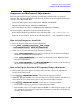
7. Observe the phase locked loop error voltage:
• If “spikes” are not visible on the analyzer display (see Figure 3-25): no adjustment is
necessary.
• If “spikes” are excessive (see Figure 3-25): adjust the CAV ADJ potentiometer (see
Figure 3-24) on the A3 source bias assembly to eliminate the spikes.
• If the “spikes” persist, refer to Chapter 7 , “Source Troubleshooting.”
Figure 3-25 Display of Acceptable versus Excessive Spikes
System
SERVICE MENU ANALOG BUS ON
Meas
S PARAMETERS
ANALOG IN Aux Input
11 x1
Format
MORE REAL
Scale Ref 10 k/m
MARKER→REFERENCE