DC POWER SUPPLY HANDBOOK Application Note 90B
TABLE OF CONTENTS Introduction ...........................................................................................................................................................6 Definitions ..............................................................................................................................................................6 Ambient Temperature.....................................................................................................................................
Typical Switching Regulated Power Supplies ...............................................................................................27 Summary of Basic Switching Regulator Configurations ...............................................................................30 SCR Regulation..............................................................................................................................................31 Constant Current Power Supply ................................................
Constant Voltage Remote Programming With Voltage Control .......................................................................84 Programming with Unity Voltage Gain .........................................................................................................84 Programming with Variable Voltage Gain ....................................................................................................85 Constant Current Remote Programming............................................................
INTRODUCTION Regulated power supplies employ engineering techniques drawn from the latest advances in many disciplines such as: low-level, high-power, and wideband amplification techniques; operational amplifier and feedback principles; pulse circuit techniques; and the constantly expanding frontiers of solid state component development.
AUTO-PARALLEL POWER SUPPLY SYSTEM AUTOMATIC (AUTO) SERIES OPERATION A master-slave series connection of the outputs of two or more power supplies used for obtaining a voltage greater than that obtainable from one supply. Auto-Series operation, which is permissible up to 300 volts off ground, is characterized by one-knob control, equal or proportional voltage sharing, and no internal wiring changes.
AUTOMATIC (AUTO) TRACKING OPERATION A master-slave connection of two or more power supplies each of which has one of its output terminals in common with one of the output terminals of all of the other power supplies. Auto-Tracking operation is characterized by one-knob control, proportional output voltage from all supplies, and no internal wiring changes. Useful where simultaneous turn-up, turn-down or proportional control of all power supplies in a system is required.
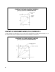
CONSTANT CURRENT POWER SUPPLY OUTPUT CHARACTERISTICS CONSTANT VOLTAGE POWER SUPPLY A regulated power supply that acts to maintain its output voltage constant in spite of changes in load, line, temperature, etc. Thus, for a change in load resistance, the output voltage of this type of supply remains constant while the output current changes by whatever amount necessary to accomplish this.
CONSTANT VOLTAGE/CONSTANT CURRENT (CV/CC) OUTPUT CHARACTERISTIC CONSTANT VOLTAGE/CURRENT LIMITING (CV/CL) POWER SUPPLY A supply similar to a CV/CC supply except for less precise regulation at low values of load resistance, i.e., in the current limiting region of operation. One form of current limiting is shown above.
CROWBAR CIRCUIT An overvoltage protection circuit that monitors the output voltage of the supply and rapidly places a short circuit (or crowbar) across the output terminals if a preset voltage level is exceeded. CURRENT FOLDBACK Another form of current limiting often used in fixed output voltage supplies. For load resistance smaller than the crossover value, the current, as well as the voltage, decreases along a foldback locus.
LOAD EFFECT (LOAD REGULATION) Formerly known as load regulation, load effect is the change in the steady-state value of the dc output voltage or current resulting from a specified change in the load current (of a constant-voltage supply) or the load voltage (of a constant-current supply), with all other influence quantities maintained constant.
TYPICAL OUTPUT IMPEDANCE OF A CONSTANT VOLTAGE POWER SUPPLY PARD (RIPPLE AND NOISE) The term PARD is an acronym for "Periodic and Random deviation" and replaces the former term ripple and noise. PARD is the residual ac component that is superimposed on the dc output voltage or current of a power supply. It is measured over a specified bandwidth, with all influence and control quantities maintained constant. PARD is specified in rms and/or peak-to-peak values over a bandwidth of 20Hz to 20MHz.
PROGRAMMING SPEED The maximum time required for the output voltage or current to change from an initial value to within a tolerance band of the newly programmed value following the onset of a step change in the programming input signal. Because the programming speed depends on the loading of the supply and on whether the output is being programmed to a higher or lower value, programming speed is usually specified at no load and full load and in both the up and down directions.
REMOTE SENSING (REMOTE ERROR SENSING) A means whereby a constant voltage power supply monitors and regulates its output voltage directly at the load terminals (instead of the power supply output terminals). Two low current sensing leads are connected between the load terminals and special sensing terminals located on the power supply, permitting the power supply output voltage to compensate for IR drops in the load leads (up to a specified limit).
STABILITY (SEE DRIFT) TEMPERATURE COEFFICIENT For a power supply operated at constant load and constant ac input, the maximum steady-state change in output voltage (for a constant voltage supply) or output current (for a constant current supply) for each degree change in the ambient temperature, with all other influence quantities maintained constant. WARM UP TIME The time interval required by a power supply to meet all performance specifications after it is first turned on.
PRINCIPLES OF OPERATION Electronic power supplies are defined as circuits which transform electrical input power--either ac or dc--into output power--either ac or dc. This definition thus excludes power supplies based on rotating machine principles and distinguishes power supplies from the more general category of electrical power sources which derive electrical power from other energy forms (e. g., batteries, solar cells, fuel cells).
A simple unregulated power supply consisting of only a rectifier and filter is not capable of providing a ripple free dc output voltage whose value remains reasonably constant. To obtain even a coarse approximation of the ideal output characteristic of Figure 1, some type of control element (regulator) must be included in the supply. Regulating Techniques Most of today's constant voltage power supplies employ one of these four regulating techniques: a. Series (Linear) b. Preregulator/Series Regulator c.
Typical Series Regulated Power Supply Figure 3 shows the basic feedback circuit principle used in Agilent series regulated power supplies. The ac input, after passing through a power transformer, is rectified and filtered. By feedback action, the series regulator alters its voltage drop to keep the regulated dc output voltage constant despite variations in the ac line, the load, or the ambient temperature.
to variations of the line and load. Hence, their line and load regulation and transient recovery time* are superior to supplies using any of the other regulation techniques. These supplies also exhibit the lowest ripple and noise, are tolerant of ambient temperature changes, and with their circuit simplicity, have a high reliability. *Power supply performance specifications are described in the Definitions section of this handbook.
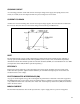
ER-ES IR = ES-EO = RR RP (1) Then multiplying both sides by RRRP, we obtain ERRP = ESRP + ESRR –EORR. (2) Figure 4 yields a second equation relating the amplifier output to its gain and voltage input EO =ES (-A) (3) which when substituted in equation (2) and solved for Es yields ER RP ES = RP + RR (1+A) (4) Normally, the operational amplifier gain is very high, commonly 10,000 or more.
Figure 5. Operational Amplifier with DC Input Signal A large electrolytic capacitor is then added across the output terminals of the operational amplifier. The impedance of this capacitor in the middle range of frequencies (where the overall gain of the amplifier falls off and becomes less than unity) is much lower than the impedance of any load that might normally be connected to the amplifier output.
(2) The use of a fixed dc input voltage means that the output voltage can only be one polarity, the opposite of the reference polarity.** (3) The series regulator can conduct current in only one direction. This, together with the fact that the rectifier has a given polarity, means that the power supply can only deliver current to the load, and cannot absorb current from the load.
minimizing size increases. Figure 7 shows an earlier Agilent power supply using SCR's as the preregulating elements. Silicon Controlled Rectifiers, the semiconductor equivalent of thyratons, are rectifiers which remain in a non-conductive state, even when forward voltage is provided from anode to cathode, until a positive trigger pulse is applied to a third terminal (the gate).
half cycle of input ac and hold the voltage drop across the series regulator constant in spite of changes in load current, output voltage, or input line voltage. Figure 8 shows how varying the conduction angle of the SCR's affects the amplitude of the output voltage and current delivered by the SCR bridge rectifier of Figure 7. An earlier firing point results in a greater fraction of halfcycle power from the bridge and a higher dc level across the input filter capacitance.
switching power transistors, fast recovery diodes, and new filter capacitors with lower series resistance and inductance, have propelled switching supplies to a position of great prominence in the power supply industry. Presently, switching supplies still have a strong growth potential and are constantly changing as better components become available and new design techniques emerge.
voltage across it. In a switching supply, however, the input ac is rectified directly (Figure 9) and the filter capacitor is allowed to charge to a much higher voltage (the peaks of the ac line). Since the energy stored in a capacitor = 0.5CV2, while its volume (size) tends to be proportional to CV, storage capability is better in a switching supply.
Included, but not shown, in the modulator chip are additional circuits that establish a minimum "dead time" (off time) for the switching transistors. This ensures that both switching transistors cannot conduct simultaneously during maximum duty cycle conditions. Figure 10. Switching Regulated Constant Voltage Supply Ac Inrush Current Protection.
future switching supplies. Preregulated Switching Supply. Figure 11 shows another higher power switching supply similar to the circuit of Figure 10 except for the addition of a triac preregulator. Operation of this preregulator is similar to the previously described circuit of Figure 7. Briefly, the dc input voltage to the switches is held relatively constant by a control circuit which issues a phase adjusted firing pulse to the triac once during each half-cycle of the input ac.
catch diode) was not required in the two transistor regulators of Figures 10 and 11 because of their full-wave rectifier configuration. Another item not found in the previous regulators is "flyback" diode CRF. This diode is connected to a third transformer winding which is bifilar wound with the primary. During the off periods of the switch, CRF is forward biased, allowing the return of surplus magnetizing current to the input filter, and thus preventing saturation of the transformer core.
Figure 13. Basic Switching Regulator Configurations Configuration B is a useful alternative to push-pull operation for lower power requirements It is called a forward, or feed-through, converter because energy is transferred to the power transformer secondary immediately following turn-on of the switch. Although the ripple frequency is inherently lower, output ripple amplitude can be effectively controlled by the choke in the output filter.
Figure 14 illustrates a typical SCR regulated supply whose output is continuously variable down to near zero volts. Circuit operation is very similar to the SCR preregulators described previously, except that the SCR control circuit receives its input from the voltage comparison amplifier. The control circuit computes the firing time for the SCRs, varying this in a manner which will result in a constant output despite changes in line voltage or load resistance.
Figure 15. Ideal Constant Current Power Supply Output Characteristic Any one of the four basic constant voltage regulators can also furnish a constant current output provided that its output voltage can be varied down to zero, or at least over the output voltage range required by the load. Besides the regulator, the reference and control circuits required for constant current operation are nearly identical to those used for constant voltage operation.
Figure 16. Constant Current Power Supply CONSTANT VOLTAGE/CONSTANT CURRENT (CV/CC) POWER SUPPLY Because of its convenience, versatility, and inherent protection features, many Agilent supplies employ the CV/CC circuit technique shown in Figure 17. Notice that only low power level circuitry has been added to a constant voltage supply to make it serve as a dual-purpose source. Two comparison amplifiers are included in a CV/CC supply for controlling output voltage and current.
Figure 17. Constant Voltage/Constant Current CV/CC Power Supply Figure 18 illustrates the output characteristic of an ideal CV/CC power supply. With no load attached (RL= ∞), IOUT= 0, and EOUT= ES, the front panel voltage control setting. When a load resistance is applied to the output terminals of the power supply, the output current increases, while the output voltage remains constant; point D thus represents a typical constant voltage operating point.
Figure 18. Operating Locus of a CV/CC Power Supply Full protection against any overload condition is inherent in the Constant Voltage/Constant Current design principle because all load conditions cause an output that lies somewhere on the operating locus of Figure 18. For either constant voltage or constant current operation, the proper choice of ES and Is insures optimum protection for the load device as well as full protection for the power supply.
operation. Thus, the current limiting locus of Figure 19 slopes more than that of Figure 18, and the crossover “knee" is more rounded. A sharp knee indicates continuous regulation through the crossover region while a rounded knee denotes loss of regulation before the crossover value is reached.
regulating elements. Thus, current foldback is especially useful if the supply is operating in a remote location and a long term short-circuit occurs. For switching regulated supplies, current foldback does not significantly reduce dissipation within the supply. It does, however, provide superior load protection as mentioned previously.
B. RFI Choke - Minimizes spikes at output of supply by slowing down turn-on of triac. C. Rectifier Damping Network - RC network protects other elements in supply against short-duration input line transients. D. Series Regulator Diode - Protects the series regulator against reverse voltages which could be delivered by an active load or parallel power supply. E. Slow Start Circuit - A long time-constant network that reduces turn-on overshoot and helps limit inrush current.
possibility. The circuit insures that the power supply voltage across the load will never exceed a preset limit. This protection is valuable because of the extreme voltage sensitivity of present-day semiconductor devices. The basic elements used in most crowbars are: some method of sensing the output voltage, an SCR that will short the output, and a circuit that will reliably trigger the SCR within a time period that is short enough to avoid damage to the load.
2. The crowbar circuit creates an extra current path during normal operation of the supply, thus changing the current that flows through the current monitoring resistor. Diode CR1 keeps this extra current at a fixed level for which compensation can then be made in the constant current comparator circuit. 3. In preregulated supplies the crowbar turns off the preregulator circuit when the SCR fires, reducing the voltage drop across the series regulator and the current flow through the SCR. 4.
Figure 22A. Crowbar Response Figure 23 shows typical protection circuits that are used in Agilent switching regulated power supplies. Most of these protection circuits perform functions that are similar to those of the linear supply of Figure 21. However, their circuit placement, or the manner in which they affect the operation of the supply, is often different. Several protection circuits (such as the ac undervoltage detector) are required only in switching supplies.
Figure 23. Protection Circuits, Switching Type Supply Additional Protection - Although not shown on Figure 23, all Agilent switching supplies contain some form of overcurrent protection, usually a current foldback circuit. Also included are remote sensing protection resistors and input protection components for the comparison amplifier.
Figure 24. "Piggy-back" Power Supply As an illustrative example, assume that the low voltage rectifier supplying the series transistor of the "piggyback" supply develops approximately 40 volts, and that the main voltage source is capable of providing a maximum of 300 volts. With 20 volts normally dropped across the series regulator, the maximum output of this supply would be 320 volts; 20 volts from the "piggy-back" supply and 300 volts from the main source.
drop at approximately 20 volts, leaving approximately 20 volts across the output terminals of the "piggy-back" supply.
tens of kilovolts or more. Such a high-voltage supply would cause noise problems, would be difficult to modulate or to program rapidly, would be dangerous, very large, and would waste considerable power. Figure 25. An Ideal Current Source Electronic current regulation is a much more tractable way to obtain high output impedance, although there are still design problems, such as leakage. Leakage Versus Regulation.
Figure 26. Impedances Shunting the Load Degrade Current Regulation As shown in Figure 27, the CCB design includes three key sections which determine its unique regulating properties--the Programming/Guard Amplifier, the Main Current Regulator, and the Voltage Limit Circuit. The Programming/Guard Amplifier is an independent, variable constant voltage source, whose output voltage EG is linearly dependent upon the setting of RQ, being equal to ESRQ/RS.
Its ohmic value is large enough to give an adequate current monitoring voltage, yet small enough to minimize its temperature rise (and the resulting resistance change) caused by its own power dissipation. Figure 27.
limit mode, a high-current transient can occur if the current regulator saturates while the instrument is still in voltage limit. The Voltage Limit Circuit in Constant Current Sources virtually eliminates voltage or current overshoots and undershoots when going in and out of voltage limit, without adding any significant leakage path across the output terminals.
output terminal and the guard has no effect on the output impedance. The meter still measures the output voltage because the guard is at the same potential as the positive output terminal. The front-panel voltmeter is internally connected to guard; and if greater accuracy is needed, a voltmeter can be connected externally. Unlike other guards, such as those used on digital voltmeters, the guard in the Current Source is active and internally referenced to the positive terminal.
Figure 28. Output Characteristics of CV/CC Supplies, Conventional vs. Extended Range Example of Extended Range Power Supply Agilent Technologies uses two different design techniques in their extended range power supplies. In one type, shown on Figure 29, extended range is achieved by adding a special tap switching network ahead of a standard CV/CC series regulated feedback loop.
The main secondary winding of the power transformer has three sections, each of which has a different turns ratio with respect to the primary winding. At the beginning of each half-cycle of the input ac, the control circuit determines whether one, both, or none of the triacs will be fired. If neither triac is fired, the rectifier receives an ac input voltage that is determined by N1 turns and the input capacitor charges to a corresponding level.
Figure 30. Output Power Plot The triac control circuit also monitors the unregulated dc to provide ac line compensation. Variations in the amplitude or frequency of the ac line modify the amplitude of the unregulated dc voltage which, in turn, alter the position of the IOD1 and IOD2 decision lines. For example, both IOD lines decrease (move to the left) if the ac line voltage increases. The reverse occurs if the ac line voltage decreases.
The extended range power supply overcomes the latter problem through the use of series regulating transistors with higher voltage ratings and with thermally improved heat sinks. The heat sinks allow the series transistors to be properly cooled during the worst case conditions that are encountered during rapid down-programming. In addition, a special transistor circuit (not shown on Figure 29) provides for a more rapid discharge of the output capacitor during down-programming.
Figure 31. Bipolar Power Supply/Amplifier Drawn as a CV/CC Power Supply. The rear terminal strip on BPS/A instruments includes numerous control terminals to facilitate remote resistance programming of the CV or CC output in the power supply mode or remote dc or ac programming in the amplifier mode.
Figure 32. Bipolar Power Supply/Amplifier Drawn as an Amplifier Figure 33.
Additional circuits are also included to facilitate operation within the systems environment. The additional circuitry performs interface, isolation, storage, overcurrent protection, and status feedback functions as explained in subsequent paragraphs. Interface and Isolation. Each input and output signal, to and from a DCPS, passes through interface and isolation circuits. Interface circuits are designed to match the unit to a variety of controllers.
Status Feedback. Three feedback lines are available to furnish continuous status information to the controller. A flag line informs the computer when new voltage programming data is being processed by the DVS. Current overload and latch lines are activated if the DVS experiences a current overload or latch condition. Digital Current Source (DCS) The DCS is a bipolar Constant Current/Voltage Limiting power source.
AC AND LOAD CONNECTIONS Modern power supplies are flexible, high-performance instruments designed to deliver a constant or controlled output with a maximum of reliability and control versatility. In many cases, however, the user inadvertently degrades this performance capability by making improper wiring connections to the input or output.
12. 13. 14. 15. 16. 17. 18. Point (GP). The CP should be connected to the GP as shown in Figures 40 through 43 (unless one load is already grounded), making certain there is only one conductive path between these two points. Connections between the power supply sensing and output terminals should be removed and using shielded two-wire cable, the power supply sensing terminals should be connected to the DC Distribution Terminals as shown in Figure 49.
Autotransformers An autotransformer (or isolation transformer) connected between the ac power source and the power supply input terminals should be rated for at least 200% of the maximum rms current required by the power supply. Because a power supply input circuit does not draw current continuously, the input current wave is not sinusoidal, and the peak-to-rms ratio is generally greater than √2, and can be as high as two or more at full output.
Figure 34. Improper Load Connections DC Distribution Terminals A single pair of terminals are designated as the positive and negative "DC Distribution Terminals" (DT's). These two terminals may be the power supply output, the B+ at the load, or a separate pair of terminals established expressly for distribution. Proper location of the DT's results in improved over-all performance and reduced mutual coupling effects between separate loads using the same power supply.
If remote sensing is employed, the DT's should be located as close as possible to the load terminals - sensing leads should then be connected from the power supply sensing terminals to the DT's (see Figure 36). (See Figure 47 for further details on remote sensing.) One pair of wires should be connected directly from the power supply output terminals to the DT's, and a separate pair of leads from the DT's to each load.
The battery symbol represents an ideal constant voltage source with perfect regulation and zero output impedance at all frequencies, but every regulated power supply has some small output impedance at high frequencies. Thus a more exact circuit model for a power supply includes an equivalent source resistance and inductance as shown in Figure 37.
travel down the load distribution wires and falsely trigger one of the other loads. Figure 37. Power Supply and Load Wiring Equivalent Circuits To be effective, the high frequency impedance of local decoupling capacitors C0, C1, C2, and C3 (Figure 38) must be lower than the impedance of wires connected to the same load. Thus a decoupling capacitor must be chosen with care, with full knowledge of its inductance and effective series resistance, as well as its capacitance.
Figure 38. Local Decoupling Capacitors The ideal concept of a single "quiet" ground potential is a snare and a delusion. No two ground points have exactly the same potential. The potential differences in many cases are small, but even a difference of a fraction of a volt in two ground potentials will cause amperes of current to flow through a complete ground loop (any circuit with more than one ground point).
repeat, separating the dc distribution circuits from any conductive paths in common with ground currents will in general reduce or eliminate ground loop problems. Figure 39. Isolating Ground Loop Paths from DC System The only way to avoid such common paths is to connect the dc distribution system to ground with only one wire. Figure 39 illustrates this concept. DC (and signal) currents circulate within the DC System, while ground loop currents circulate within the Ground System.
DC Common One of the DC Distribution Terminals should be designated as the "DC Common Point” (CP). There should be only one DC Common Point per DC System. If the supply is to be used as a positive source, then the minus DC Distribution Terminal is the DC Common Point; if it is to be a negative source, then the plus DT is the CP. Here are some additional suggestions for selecting the best DC Common Point for five different classes of loads: a.
Figure 41. Preferred Ground Connections for Multiple Loads, All Isolated Figure 42. Preferred Ground Connections for Single Grounded Loads c. Single Grounded Load--The load terminals of the grounded load must be designated as the DT's and the grounded terminal of the load is necessarily the CP (Figure 42).
connection to ground or chassis--or when there are multiple loads and only one has an internal connection to ground or chassis (Figure 43). Figure 43. Ground Connections for Multiple Loads, One Grounded d. Multiple Loads, Two or More of Which are Individually Grounded--This is an undesirable situation and must be eliminated if at all possible.
Figure 44. Ground Connections for Multiple Loads, Two or More Grounded e. Load System Floated as a DC Potential Above Ground In some applications it is necessary to operate the power supply output at a fixed voltage above (or below) ground potential. In these cases it is usually advantageous to designate DC Common Point using whichever of the preceding four alternatives is appropriate, just as though conductive grounding would be employed.
DC Ground Point The CP should be connected to the GP as shown in Figures 40 through 43 (unless one load is already grounded), making certain there is only one conductive path between these two points. This connection should be such that the total impedance from the DC Common for example, be the separate ground terminal located on one of the power supplies or loads in a system, or it may be a special system ground terminal, bus, or plane established expressly for ground connection purposes.
Some idea of how easily even the shortest leads can degrade the performance of a power supply at the load terminals can be obtained by comparing the output impedance of a well-regulated power supply (typically of the order of 1 milliohm or less at dc and low frequencies) with the resistance of the various wire sizes listed in the following chart. AWG (B & S) Annealed Copper Resistance at Nominal current rating (amps)* WIRE SIZE 20°C milliohms/ft. 22 16.1 5 20 10.2 7 18 6.39 10 16 4.02 13 14 2.53 20 12 1.
Figure 48. Constant Voltage Regulator with Remote Error Sensing Remote Sensing Connections Connections between the power supply sensing and output terminals should be removed, and using shielded two-wire cable, the power supply sensing terminals should be connected to the DC Distribution Terminals as shown in Figure 49. Do not use the shield as one of the sensing conductors.
Figure 49. Remote Sensing Connections Typically, the sensing current is 10mA or less. To insure that the temperature coefficient of the sensing leads will not significantly affect the power supply temperature coefficient and stability specifications, it is necessary to keep the IR drop in the sensing conductors less than 20 times the power supply temperature coefficient (stated in millivolts/°C).
To reduce the degree of output overshoot which can result from accidentally opened remote sensing connections, many regulated power supplies include internally wired resistors or small silicon diodes as shown in Figures 50 and 51.
If the resistor configuration of Figure 50 is included by the manufacturer or added by the user, it may be necessary to check that the power rating of this resistor is adequate, particularly for sizable sensing drops. Remember that the actual dissipation in the remote sensing protection resistors is ED2/R, where ED is the IR drop from either power supply output terminal to the corresponding DT, and R is the ohmic value of the protective resistor.
power supply impedance at the load at high frequencies. However, the capacitor must be chosen with care if power supply oscillation is to be avoided, since any capacitor resonances or other tendency toward high impedance within or near the bandpass of the power supply regulator will reduce loop stability. It is therefore common in extreme remote sensing applications to remove Co from the power supply and use it as Co'.
power supply system - this point must be designated as one of the two DT's for both power supplies. Thus there are exactly (N + 1) DT's in any system, where N is the number of power supplies (excluding the possibility of parallel supplies sharing the same distribution terminals or series power supplies with unused intermediate terminals).
REMOTE PROGRAMMING Remote programming, a feature found on many Agilent power supplies, permits control of the regulated output voltage or current by means of a remotely varied resistance or voltage. It is generally accomplished by restrapping the supply's rear terminals so that the front panel control is disabled and a remote control device is connected to the supply.
Figure 54. Constant Voltage Supply with Resistance Programming Programming a power supply with a 200 ohms/volt programming coefficient to an output level of 30 volts would require and RP of 6K. The power supply will force through this programming resistor a 5mA constant current thus resulting in 30 volts across the power supply output terminals.
Figure 55. Remote Programming Connections The wire size of the programming leads must be adequate to withstand any programming surges (consider effects of any large storage capacitors which have to be charged or discharged through the programming leads). The temperature coefficient of a very long programming leads may degrade power supply temperature coefficient and drift specifications.
ohms. It appears at first glance that the circuit of Figure 56B also has one drawback -- namely, the output voltage must always be switched in ascending or descending sequence. As Figure 56C shows, however, the same voltage divider can have its tap points returned to the switch contacts in any sequence, permitting output voltage values to be programmed in any desired order without overshoot or undershoot. Figure 56.
causing the output voltage to rise to some value higher than the maximum voltage rating of the supply. With some loads this could result in serious damage. To protect loads from accidental opening of the remote programming leads, a zener diode should be placed directly across the power supply programming terminals. This zener diode is selected to have a breakdown voltage equal to the maximum power supply voltage that can be tolerated by the load.
basis. Programming with Variable Voltage Gain Figure 58 illustrates the method by which the power supply can be programmed using an external voltage with a voltage gain dependent upon the ratio of RP to RR. Note that this method is no different from the circuit normally used for constant voltage control of the output except that an external reference (the programming voltage source) has been substituted for the internal reference.
In situations where only low programming voltages are being used, forward conducting silicon diodes (0.7V per junction) can be used in place of zener diodes. CONSTANT CURRENT REMOTE PROGRAMMING Most of the general principles discussed under Constant Voltage Programming are also applicable when considering remote programming for constant current supplies. Remote programming of the constant current output of any programmable supply can be accomplished either by: 1.
Figure 59. Ideal Remote Programming Characteristics As Figure 60 indicates, all power supplies deviate somewhat from the ideal. The application of a short-circuit across the programming terminals results in an output voltage which is slightly different from zero (typically between +20 millivolts and -50 millivolts). While the linearity of the programming characteristic is nearly perfect, the overall slope may differ from the value predicted by the programming coefficient by from 1% to 5%.
accuracy will deliver zero volts with zero programming resistance. Thus, the first step in improving the programming accuracy of Figure 60 is to short the programming terminals and note the output voltage. Normally, this voltage will be slightly negative. If this is not the case the comparison amplifier packages can sometimes be interchanged; the output voltage with zero programming resistance will then, in most cases, become slightly negative.
than the new output voltage being programmed. When this exponential rise reaches the newly programmed voltage level, the constant voltage amplifier resumes its normal regulating action and holds the output constant. Thus, the rise time can be determined using a universal time constant chart or the formula shown in Figure 61.
Figure 62. Speed of Response - Programming Down Since up-programming speed is aided by the conduction of the series regulating transistor, while downprogramming normally has no active element aiding in the discharge of the output capacitor, laboratory power supplies normally program upward more rapidly than downward. In many Agilent laboratory power supplies, however, a special transistor circuit provides for the more rapid discharge of the output capacitor for downprogramming.
OUTPUT VOLTAGE AND CURRENT RATINGS DUTY CYCLE LOADING In some applications the load current varies periodically from a minimum to a maximum value. At first it might seem that a regulated power supply having a current rating in excess of the average load requirement (but less than the peak load value) would be adequate for such applications.
peak load condition. Figure 63.
peak load demand. For short term overloads, a quick approximation can be made to determine the amount of voltage sag: (IP – IL) ∆T ∆V≈ = CO where: ∆V = The voltage sag IP= ENORM RL PEAK = Peak load current demand, IL = The current limit or constant current setting, Co = The output capacitor (in farads), and ∆T = Duration of overload condition (in seconds).
DUAL OUTPUT USING RESISTIVE DIVIDER Often it is required to use both a positive and negative dc power source having approximately the same voltage and current capability. It might seem reasonable to meet such requirements using a single regulated dc supply with a resistive voltage divider center-tapped to ground.
Figure 64B. Reverse Current Loading Solution. Figure 65.
PARALLEL OPERATION The operation of two constant voltage power supplies in parallel is normally not feasible because of the large circulating current which results from even the smallest voltage difference which inevitably exists between the two low impedance sources.
of current monitoring resistors in the master and slave supplies, the output current contribution will always be equal regardless of the output voltage or current requirement of the load. Normally, only supplies having the same model number should be connected for Auto-Parallel operation, since the two supplies must have the same voltage drop across the current monitoring resistor at full current rating. As is also true of Auto-Series and Auto-Tracking operation, no internal wiring changes are necessary.
Figure 67. Auto-Series Operation of Two Supplies Comparing Figure 67 with previous block diagrams for the constant voltage power supply, there is no difference in the circuit location of Resistor R2 and the front panel voltage control normally found in Agilent laboratory type power supplies.
AUTO TRACKING OPERATION Auto-Tracking or automatic tracking operation of power supplies is similar to Auto-Series operation except that the master and slave supplies have the same output polarity with respect to a common bus or ground. Figure 68 shows two supplies connected in Auto-Tracking with their negative output terminals connected together as a common or ground point.
As Figure 69 indicates, it is only necessary to add a single external current monitoring resistor to a remote programming constant voltage power supply in order to convert it to constant current operation. (Also any remote sensing protection resistor or diode connected inside the supply from –S to - OUT must be removed.
PERFORMANCE MEASUREMENTS CONSTANT VOLTAGE POWER SUPPLY MEASUREMENTS Figure 70 illustrates a setup suitable for the measurement of the six most important operating specifications of a constant voltage power supply: source effect, load effect, PARD, load effect transient recovery time, drift, and temperature coefficient. The automatic load switch shown in Figure 70 is used to periodically interrupt the load when measuring transient recovery time.
Figure 70. Constant Voltage Measurement Setup Failure to connect the monitoring instrument to the proper points shown in Figure 71 will result in the measurement not of the power supply characteristics, but of the power supply plus the resistance of the leads between its output terminals and the point of connection. Even using clip leads to connect the load to the power supply terminals and the monitoring instrument to the load leads can result in a serious measurement error.
A. FRONT PANEL B. REAR PANEL Figure 71. Proper Connections for Monitoring and Load Leads Check Current Limit Control Setting. When measuring the constant voltage performance specifications, the constant current or current limit control must be set well above the maximum output current that the supply will draw.
supply, connect both leads to either the positive or the negative sensing terminals, whichever is grounded to chassis. Signals on the face of the CRT as a result of either of these tests are indicative of shortcomings in the measurement setup. The most likely causes of these defects and proper corrective measures are discussed further under CV PARD (Ripple and Noise). Connect AC Voltmeter Properly.
The power supply will perform within its load effect specification at any rated output voltage combined with any rated input line voltage. CV PARD (Ripple and Noise) Definition: The term PARD replaces the former term ripple and noise. PARD is the Periodic and Random Deviation of the dc output voltage from its average value, over a specified bandwidth and with all other parameters maintained constant.
Figure 72. Measurement of PARD (Ripple and Noise) for a CV Supply Either a twisted pair or preferably a shielded two-wire cable should be used to connect the output terminals of the power supply to the vertical input terminals of the scope. When using shielded two wire, it is essential for the shield to be connected to ground at one end only so that no ground current will flow through this shield preventing induced noise signals in the shielded leads.
measurements where both the power supply and the oscilloscope case are connected to ground (e. g., if both are rack-mounted), it may be necessary to use a differential scope with floating input as shown in Figure 72C. If desired, two single-conductor shielded cables may be substituted in place of the shielded two-wire cable.
Noise Spike Measurements When a high frequency spike measurement is being made, the oscilloscope must have a bandwidth of 20MHz or more. Measuring noise with an instrument that has insufficient bandwidth may conceal high frequency spikes detrimental to the load. The test setups illustrated in Figures 72A and 72B are generally not acceptable for measuring spikes; a differential oscilloscope is necessary.
CV Load Effect Transient Recovery Time (Load Transient Recovery) Definition: The time "X" for the output voltage to recover and to stay within "Y" millivolts of the nominal output voltage following a "Z" amp step change in load current, where: "Y" is specified separately for each model but is generally of the same order as the load regulation specification. The nominal output voltage is defined as the dc level half way between the steady state output voltage before and after the imposed load change.
transient recovery time of a power supply, the spike amplitude for load switching times of less than 1 microsecond cannot be accurately determined, unless a very wideband scope is used. Of all power supply specifications, transient recovery time is subject to the widest variation in definition, and is not defined at all by some power supply manufacturers. Specifying that a power supply has a transient recovery time of "50 microseconds" is incomplete and conveys no information.
CV Drift (Stability) Definition: The change in output voltage (dc to 20Hz) for the first eight hours following a 30 minute warm-up period. During the warm-up and measurement interval all parameters, such as load resistance, ambient temperature, and input line voltage are held constant. Drift includes periodic and random deviations over a bandwidth from zero frequency (dc) to an upper limit of 20Hz.
downprogramming. This is done to present the worst possible conditions for programming in each direction. A method for measuring the programming speed of an Agilent power supply is as follows: Figure 77. CV Programming Speed Test Setup 1. Restrap the power supply rear barrier strip for remote resistance programming, constant voltage. The strapping pattern for remote resistance programming of laboratory-type power supplies is illustrated in each Agilent Operating and Service Manual. 2.
and the output voltage (EOUT) in both the up and down programming directions. Figure 78. Typical Programming Speed Waveforms The constant voltage programming speed of a power supply using a remote programming voltage is identical to the speed obtained when using a remote resistance provided that the remote voltage changes rapidly enough.
the power supply which will be shorted to ground. All constant current measurements are made in terms of the change in voltage across this resistor; the current performance is calculated by dividing these voltage changes by the ohmic value of RM. Figure 79. Constant Current Measurement Setup Many of the precautions listed for the previous constant voltage measurement setup are equally applicable to a constant current setup.
Figure 80. Four-Terminal Current Monitoring Resistor Keep Temperature of RM Constant Resistor RM should be protected against stray air currents (open doors or windows, air conditioning vents), since these will change the resistance value, degrading the stability and temperature coefficient measurements. Check Voltage Control Setting.
Figure 81. External Voltmeter Measurement Error on CC Power Supply CC Source Effect (Line Regulation) Definition: The change ∆IOUT in the steady state value of dc output current due to a change in ac input voltage over the specified range from low line (e. g., 104 volts) to high line (e. q., 127 volts), or from high line to low line.
Most of the comments pertaining to the ground loop and pickup problems associated with constant voltage ripple and noise measurement also apply to the measurement of constant current ripple and noise. Figure 82 illustrates the most important precautions to be observed when measuring the ripple and noise of a constant current supply. The presence of a 2fL waveform on the oscilloscope is normally indicative of a correct measurement method.
Figure 82.
CC Temperature Coefficient Definition: The change in output current per degree Celsius change in the ambient temperature following a 30 minute warm-up. During the measurement interval the ac line voltage, output current setting and load resistance are held constant. The constant current power supply must be placed in an oven and operated over any temperature span within the power supply rating.
INDEX A AC power, input connections input wire size ................................................................................................................... 61 interchanging ac and acc leads .......................................................................................... 60 interchanging ac and ground leads .................................................................................... 60 Ambient temperature, definition ..............................................................
constructed from constant voltage supply......................................................................... 99 definition ............................................................................................................................. 8 limitations ......................................................................................................................... 33 output capacitance.....................................................................................................
E Efficiency, definition..................................................................................................................... 11 of preregulated supplies .................................................................................................... 23 of SCR regulated supplies................................................................................................. 27 of series regulated supplies ...................................................................................
of high performance constant current supply.................................................................... 49 measurement method .............................................................................................. 112, 119 Inrush current, definition............................................................................................................... 11 protection ....................................................................................................................
transient recovery .................................................................................................... 107, 117 Piggy-Back regulator, definition ................................................................................................... 44 Power supply/amplifier ................................................................................................................. 54 Preregulator, definition ..................................................................................
S Safety ground, in power cord ........................................................................................................ 68 Sampling resistor (see current monitoring resistor) SCR's, definition ........................................................................................................................... 24 in preregulator circuit........................................................................................................ 24 in regulator circuits .......................
Agilent Technologies’ Test and Measurement Support, Services, and Assistance Agilent Technologies aims to maximize the value you receive, while minimizing your risk and problems. We strive to ensure that you get the test and measurement capabilities you paid for and obtain the support you need. Our extensive support resources and services can help you choose the right Agilent products for your applications and apply them successfully. Every instrument and system we sell has a global warranty.