
User manual


22 User Manual
3 Computer Connection
Configuring a GPIB/RS-232 MIO Card
The GPIB/RS-232 MIO card allows the host computer to communicate with the
35900 through either an RS-232 or a GPIB connection. By setting the
configuration switches on the card you can configure the type of connection
desired. Review your data system’s installation instructions to determine
compatibility.
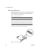
If necessary, the board switch settings can be inspected or changed by
removing the board from the rear of the unit.
1 Turn the unit off and remove the power cord.
2 Loosen the thumb screws on the back of the unit and then pull on the back
plate of the MIO card to remove it from the unit.
Configuration for GPIB operations
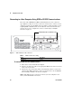
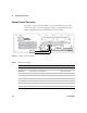
The GPIB/RS-232 MIO card contains an 8–position configuration switch.
When the position 1 switch is set to OFF, the MIO card uses the GPIB
communication mode. In this mode, the ON switch position for switches 2
through 8 are defined in Table 2 and shown in Figure 5.
The factory default setting for this switch is shown in Figure 5. Because switch
1 is set to OFF, the board is in GPIB mode. Switch 3 indicates that SRQ
(Service Request) is enabled. Switches 5, 6 and 8 set to ON and switches 4 and
7 set to OFF combine to form a GPIB instrument address of 13 (0+8+4+0+1).
The most common reason for changing this switch setting is to avoid GPIB
address conflicts. Conflicts occur when two or more instruments on the bus
have identical GPIB addresses.
Verify the card address is not already in use, and that it is not 7 (address 7 is
reserved). To change the address when a conflict exists, select a new address
not used by any other instrument on this GPIB bus. For example, to use 20 as
the new address, set switches 4 and 6 ON and switches 5, 7, and 8 OFF
(16+0+4+0+0=20).