
User manual


Computer Connection 3
User Manual 25
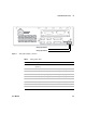
Because switch 1 is set to ON, the board is in RS-232 mode. Switch 2 set to ON
indicates that handshaking is enabled. With handshake enabled, switch 3 set
to OFF indicates software handshaking. Switch 4 set to ON enables parity
checking. Switch 5 set to OFF indicates odd parity.
Switches 6 through 8 combine to indicate baud rate. See Table 4 for switch
settings and their corresponding baud rates. Switches 6 and 8 set to ON and 7
set to OFF combine to form a RS-232 baud rate of 9600 as shown in Table 4.
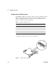
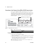
Installing the communication card
After you have configured your data communications card as described above,
you can install it in your 35900.
1 Remove the power supply cord from the rear of the unit.
2 Slide the MIO card into the back of the 35900 so that its two side edges slide
into the guide rails.
3 Slide the card in until you feel it seat in the connector at the rear of the slot.
4 Secure the card with the two thumb screws provided on the card.
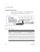
Ta bl e 4 Example settings for RS-232 baud rates
Switch
Baud rate 6 7 8
300 OFF OFF OFF
600 OFF OFF ON
1200 OFF ON OFF
2400 OFF ON ON
4800 ON OFF OFF
9600 ON OFF ON
19,200 ON ON OFF
38,400 ON ON ON
CAUTION
To avoid damaging the board, follow electrostatic discharge (ESD) precautions. See
“Electrostatic discharge is a threat to 35900 electronics” on page 11