
User manual


28 User Manual
4 Instrument Connection
Analog Input (Signal) Connection
The signal must be within the range of -18 millivolts to 1 volt. A simple voltage
divider resistor network may be used to attenuate larger signals to this range.
Each input has three pins to which the high (+) and low (–) sides of the signal
and the shield are connected.
Use an instrument-specific cable (Table 6) whenever possible. Use a general
purpose cable in those cases where a custom cable is not available.
Appendix A lists pin assignments for all open cables.
1 Turn off the power to the instrument supplying the analog output signal.
2 For instrument-specific cables–Connect one end of the cable to the
instrument's analog output using the instrument manufacturer's
instructions.
For general purpose cables – Use the pin assignments shown in
Appendix A, “Cables, and the instrument manufacturer's instructions to
connect the two signal wires and ground to the instrument.
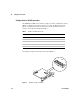
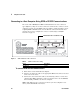
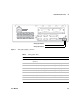
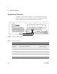
3 Connect the cable to the appropriate (A or B) analog input on the rear
panel of the 35900 (Figure 8).
4 If needed, repeat for the other channel.
CAUTION
For correct operation of the 35900, the input voltage must be in the range of -18 me to
+1 V. Voltages below –10 V or above +10 V may damage the instrument.