
User`s guide

Getting Started with the Agilent 81600B Tunable Laser Source Family Optical Output
22 Agilent 81600B Tunable Laser Source Family, Fourth Edition
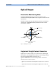
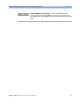
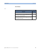
Figure 4 Angled and Straight Contact Connector Symbols
Figure 4 shows the symbols that tell you whether the contact connector
of your Tunable Laser Source module is angled or straight. The angled
contact connector symbol is colored green.
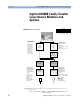
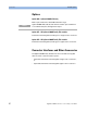
Figure 2 and Figure 5 shows the front panel of the Agilent 81600B
Family Tunable Laser Source module with straight and angled contact
connectors respectively.
You should connect straight contact fiber end connectors with neutral
sleeves to straight contact connectors and connect angled contact fiber
end connectors with green sleeves to angled contact connectors.
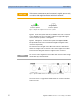
Figure 5 Agilent 81600B Tunable Laser Module (angled contact connector)
See “Accessories” on page 25 for further details on connector interfaces
and accessories.
If the contact connector on your instrument is angled, you can only
use cables with angled connectors with the instrument.
CAUTION
Straight Contact
Connector Symbol
Angled Contact
Connector Symbol
You cannot connect angled non-contact fiber end connectors with orange
sleeves directly to the instrument.
NOTE