
User`s guide
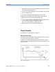

Performance Tests Power Tests
98 Agilent 81600B Tunable Laser Source Family, Fourth Edition
4
4For the Agilent 81600B #130, #140, #150, #160 and #200 TLS
modules, connect the output fiber to Output 2, the High Power output
Set <Optical Output> to <High Power (2)>.
5 Make sure the optical output is switched off.
6 At the 81624A/B:
a Zero the 81624A/B. Select <Menu> then <Zero>,
b Automatic ranging is set by default
c Set the Averaging Time to 500 ms,
d Select <dB> as the power units,
e Set λ, the wavelength, to the same as the TLS module, as given in
step 3.
7 Switch on the High Power output of the TLS.
8 Note the power value displayed by the 81624A/B in the Test Record.
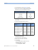
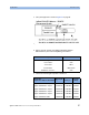
[For the 81600B #200, #160, #150, #140 and #130 use the Test Record
table “Power Linearity Output 2, High Power by attenuator”.
For the 81600B #142 #003 use the Test Record table “Power Linearity
81600B #142 #003, High Power by attenuator”.]
9 At the 81624A/B, select <Menu> then <Disp → Ref>
10 Change the power setting of the TLS to the next value given in the Test
Record.
11 Note the (relative) power displayed by the 81624A/B as the “Measured
Relative Power from start”.
12 Calculate the "Power Linearity at current setting" as the sum of
"Measured Relative Power from start" and "Power Reduction from
start".
13 Repeat step 10 to step 12 for all power levels listed in the Test Record.
14 Determine the maximum value and the minimum value of the
calculated Power Linearity at the various settings and record them in
the Test Record as "Maximum Power Linearity at current setting", and
"Minimum Power Linearity at current setting", respectively.
15 Subtract the minimum power linearity value from the maximum power
linearity value and record the result as the Tota l Po we r Li ne ar ity.
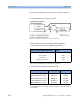
[For example, refer to Ta b le .]