Agilent E5250A Low Leakage Switch Mainframe User’s Guide Agilent Technologies
Notices © Agilent Technologies 1995 - 2008 Warranty No part of this manual may be reproduced in any form or by any means (including electronic storage and retrieval or translation into a foreign language) without prior agreement and written consent from Agilent Technologies, Inc. as governed by United States and international copyright laws. The material contained in this document is provided “as is,” and is subject to being changed, without notice, in future editions.
DECLARATION OF CONFORMITY According to ISO/IEC Guide 22 and CEN/CENELEC EN 45014 Manufacturer’s Name: Manufacturer’s Address: Supplier’s Address: Agilent Technologies International sarl Rue de la Gare 29 CH - 1110 Morges Switzerland Declares under sole responsibility that the product as originally delivered Low Leakage Switch Mainframe 10x12 Matrix Switch24(8x3)CH Multiplexer 24(8x3)CH Multiplexer Agilent E5250A Agilent E5252A Agilent E5255A This declaration covers all options of the above product(s) Pr
• Herstellerbescheinigung GEÄUSCHEMISSION Lpa < 70 dB am Arbeitsplatz normaler Betrieb nach DIN 45635 T. 19 • Manufacturer’s Declaration ACOUSTIC NOISE EMISSION Lpa < 70 dB operator position normal operation per ISO 7779 NOTE This ISM device complies with Canadian ICES-001. Cet appareil ISM est conforme ?Hla norme NMB-001 du Canada. This product complies with the WEEE Directive (2002/96/EC) marking requirements.
Safety Summary The following general safety precautions must be observed during all phases of operation, service, and repair of this instrument. Failure to comply with these precautions or with specific warnings elsewhere in this manual may impair the protections provided by the equipment. In addition, it violates safety standards of design, manufacture, and intended use of the instrument. Agilent Technologies, Inc. assumes no liability for customer’s failure to comply with these requirements.
• DO NOT SUBSTITUTE PARTS OR MODIFY INSTRUMENT Because of the danger of introducing additional hazards, do not install substitute parts or perform any unauthorized modification to the instrument. Return the instrument to a Agilent Technologies Sales and Service Office for services and repair to ensure that safety features are maintained. • DANGEROUS PROCEDURE WARNINGS Warnings, such as example below, precede potentially dangerous procedures throughout this manual.
Safety Symbols The general definitions of safety symbols used on equipment or in manuals are listed below. Instruction manual symbol: the product will be marked with this symbol when it is necessary for the user to refer to the instruction manual in order to protect against damage to the instrument. Indicates dangerous voltage and potential for electrical shock. Do not touch terminals that have this symbol when insrument is on.
In This Manual This manual is a user’s guide for Agilent E5250A, and consists of the following chapters: • Introduction Provides an overview of the E5250A Low Leakage Switch Mainframe, E5252A 10×12 Matrix Switch, and E5255A 24 (8×3) Channel Multiplexer. • Installation Describes requirements to install the E5250A and tasks for installation.
• Specifications Lists specifications, typical data, supplemental data, and reference data for the E5250A, E5252A, and E5255A. • Error Messages Lists and describes the error messages for the E5250A. • SCPI Command Summary This is a quick reference for the SCPI subsystem commands available for the E5250A. Text Conventions The following text conventions are used in this manual: Screen Text Represents text that appears on screen of the controller.
Contents 1. Introduction Agilent E5250A Product Description . . . . . . . . . . . . . . . . . . . . . . . . . . . . . . . . . . 1-3 Front Panel Tour . . . . . . . . . . . . . . . . . . . . . . . . . . . . . . . . . . . . . . . . . . . . . . . . 1-4 Rear Panel Tour . . . . . . . . . . . . . . . . . . . . . . . . . . . . . . . . . . . . . . . . . . . . . . . . . 1-4 . . . . . . . . . . . . . . . . . . . . . . . . . . . . . . . . . . . . . . . . . . . . . . . . . . . . . . . . . . . . .
Contents Maintenance. . . . . . . . . . . . . . . . . . . . . . . . . . . . . . . . . . . . . . . . . . . . . . . . . . . . . 2-18 Performance Verification . . . . . . . . . . . . . . . . . . . . . . . . . . . . . . . . . . . . . . . . . 2-18 Cleaning . . . . . . . . . . . . . . . . . . . . . . . . . . . . . . . . . . . . . . . . . . . . . . . . . . . . . 2-18 3. Executing Self-Test and Leak Test Executing Self-Test . . . . . . . . . . . . . . . . . . . . . . . . . . . . . . . . . . . . . . . . . . . . . .
Contents To Connect the E5252A Output . . . . . . . . . . . . . . . . . . . . . . . . . . . . . . . . . . . 4-20 To Connect the E5255A Output . . . . . . . . . . . . . . . . . . . . . . . . . . . . . . . . . . . 4-22 Measurement Cable Length . . . . . . . . . . . . . . . . . . . . . . . . . . . . . . . . . . . . . . . . 4-23 5. Controlling the E5250A Methods for Controlling the E5250A . . . . . . . . . . . . . . . . . . . . . . . . . . . . . . . . . . 5-3 Creating Your Own Program . . . . . . . . . . . . .
Contents Controlling E5250A by Using HP BASIC . . . . . . . . . . . . . . . . . . . . . . . . . . . . 6-5 Creating a Control Program . . . . . . . . . . . . . . . . . . . . . . . . . . . . . . . . . . . . . . . . . 6-6 Defining Channel Configuration Mode . . . . . . . . . . . . . . . . . . . . . . . . . . . . . . 6-8 Defining Connection Rule . . . . . . . . . . . . . . . . . . . . . . . . . . . . . . . . . . . . . . . . 6-8 Defining Connection Sequence . . . . . . . . . . . . . . . . . . . . . . . . . . .
Contents Status Reporting Structure . . . . . . . . . . . . . . . . . . . . . . . . . . . . . . . . . . . . . . . . . 7-48 Status Reporting Structure . . . . . . . . . . . . . . . . . . . . . . . . . . . . . . . . . . . . . . . . 7-48 Status Byte Register . . . . . . . . . . . . . . . . . . . . . . . . . . . . . . . . . . . . . . . . . . . . 7-50 Service Request Enable Register . . . . . . . . . . . . . . . . . . . . . . . . . . . . . . . . . . . 7-52 Standard Event Status Register . . . . . . . . . . . .
Contents 12.
1 Introduction
Introduction This chapter gives an overview of Agilent E5250A, E5252A, and E5255A.
Introduction Agilent E5250A Product Description Agilent E5250A Product Description Agilent E5250A Low Leakage Switch Mainframe is a computer-controlled switching matrix mainframe designed for semiconductor dc characteristics measurement applications. The E5250A has four slots for installing the modules (plug-in cards) listed in Table 1-1. These cards can be used in various switching matrix configurations in the E5250A.
Introduction Agilent E5250A Product Description Front Panel Tour The E5250A has 2 hard keys and 4 LED indicators on the front panel as shown in Figure 1-1. LINE key Used to turn the E5250A on or off. Line LED Turns on when the E5250A is turned on. Local/Self Test key If "Remote" LED is on, pressing this key releases the E5250A from remote GPIB control by an external controller. If "Remote" LED is off, pressing this key executes the Relay Test.
Introduction Agilent E5250A Product Description AUX INPUT AUX INPUT connectors are for C-V measurements, pulse input, and so on. The E5250A has 4 AUX INPUT ports: HF1, HF2, CV1, CV2. These are BNC type connectors. The AUX INPUT connectors are used only with the E5252A and are not used with the E5255A. CAUTION The maximum measurement voltage that can be applied to any input terminal is ±200 Vdc. The maximum measurement current is 1 Adc at ±200 Vdc.
Introduction Agilent E5252A Product Description Agilent E5252A Product Description The E5252A 10×12 Matrix Switch is a 10-input to 12-output switching matrix card for the E5250A. The E5252A is designed for semiconductor dc parametric measurement applications that need to switch some instruments connected to Device Under Test (DUT), or need to scan instrument input/output for many DUTs, automatically. The E5250A can be installed with maximum four E5252As.
Introduction Agilent E5252A Product Description Input Ports The E5252A has 10 input ports via the E5250A. Input paths for SMU1 and SMU2 are designed for low current measurement. There are actually only six input paths, so two of the input paths are shared by three ports each as follows: • SMU5, HF1, and CV1 ports share same input path • SMU6, HF2, and CV2 ports share same input path So, for these two input paths, you can only use one input port at a time.
Introduction Agilent E5255A Product Description Agilent E5255A Product Description The E5255A 24 (8×3) Channel Multiplexer is a 2-input to 24-output multiplexer card for the E5250A. The E5255A consists of 3 blocks (three 2×8 multiplexers). So, one E5255A can be configured as a 2×8 multiplexer, 2×16 multiplexer, or 2×24 multiplexer. "2-input" means one BIAS input and one IV input.
Introduction Agilent E5255A Product Description Resistors Resistors connected between BIAS path and IV path are for protecting DUT from electrical damage. When shipped from factory, 0 Ω resistance is used in the E5255A. You can easily replace with desired resistors. Refer to Chapter 2. The following resistors are furnished with the E5255A: • 0 Ω resistors (3 sets with 10 resistors in each set) • 1.
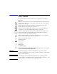
Introduction Agilent E5255A Product Description Figure 1-5 E5255A Block Diagram B LO C K 1 B IA S Inpu t 1 R esis tor IV Input 1 O u tpu t 1 2 3 4 5 6 7 8 13 14 15 16 21 22 23 24 B LO C K 2 B IA S Inpu t 2 R esis tor IV Input 2 O u tpu t 9 10 11 12 BLO C K 3 B IA S Input 3 R esis tor IV In put 3 O u tpu t 1-10 17 18 19 20 Agilent E5250A User’s Guide, Edition 9
Introduction Agilent E5255A Product Description Table 1-2 E5255A Input/Output Connectors 2×8 multiplexer Block No. BIAS INPUT (Port No.) Output Port No. OUTPUT Connector (Location) Block1 BIAS1 (51) Output 1 to 8 Left Block2 BIAS2 (52) Output 9 to 16 Center Block3 BIAS3 (53) Output 17 to 24 Right Figure 1-6 E5255A BIAS INPUT Connectors and OUTPUT Connectors WARNING Do not touch the force and guard terminals of the OUTPUT connectors while the E5250A is turned on.
Introduction Options and Accessories Options and Accessories This section lists the options and accessories available for the E5250A. Table 1-3 lists the options available for the E5250A. Table 1-3 Options Model Number Option Item E5250A 1-12 Description Low Leakage Switch Mainframe E5250A-301 Relay Test Adapter E5250A-A6J ANSI Z540 compliant calibration E5250A-UK6 Commercial cal.
Introduction Options and Accessories Table 1-4 lists accessories furnished with the E5250A, E5252A, and E5255A. Table 1-4 Furnished Accessories Model Number Part Number E5250A E5250-90000 Agilent E5250A User's Guide 1 E5250-17001 E5250A VXI Plug&Play Driver Disk a 1 E5250-17003 Agilent E5250A Program Disk. See next page. (LIF formatted, 3.
Introduction Options and Accessories Contents of the E5250A Program Disk: Virtual Front Panel Utility Interactive control program for the E5250A. Runs on Agilent 4155/4156's built-in IBASIC controller. Refer to Chapter 5. VFP Data Upload Library Subprogram library used for uploading the E5250A control data (made by Virtual Front Panel Utility) to your program. Runs on HP BASIC. Refer to Chapter 6.
Introduction Options and Accessories Table 1-5 lists accessories available for the E5250A. Table 1-5 Available Accessories Model Number Option Item Description E5252A 10×12 Matrix Switch E5255A 24 (8×3) Channel Multiplexer 16494A Triaxial Cable 16494A-001 1.5 m length 16494A-002 3 m length 16494A-003 80 cm length 16494B Kelvin Triaxial Cable (4156 kelvin to E5250 kelvin) 16494B-001 1.
Introduction Options and Accessories 1-16 Agilent E5250A User’s Guide, Edition 9
2 Installation
Installation This chapter describes requirements to install Agilent E5250A and the tasks for installation, and is organized into the following three sections: WARNING • “To Inspect the E5250A and Accessories” describes how to inspect the E5250A when you receive it. • “Requirements” explains the information required for operating, storing, and shipping the E5250A. • “Installing the E5250A” describes how to install the E5250A. • “Maintenance” describes about performance verification and cleaning.
Installation To Inspect the E5250A and Accessories To Inspect the E5250A and Accessories When you receive and open the box that contains the E5250A, check the following: • Before unpacking any components, inspect all boxes for any signs of damage that might have occurred during shipment such as: • Dents • Scratches • Cuts • Water marks • When you open the boxes that contain the E5250A, check the components against the contents lists that are attached to the boxes.
Installation Requirements Requirements This section describes the following requirements for the E5250A. • “Power Requirements” • “Power Cable” • “Operating Environment” • “Storage and Shipping Environment” Power Requirements CAUTION Before applying ac line power to the E5250A, ensure that the correct power cable is used. The E5250A can operate from any single-phase ac power source supplying 100 to 240 V ±10 % in the frequency range from 47 to 63 Hz. The maximum power consumption is 100 VA.
Installation Requirements • • • • • • • • • Plug: BS 1363/A, 250 V, 10 A Cable: 8120-4420, 8120-1351 • Plug: NEMA 6-15P, 250 V, 10 A Cable: 8120-3996, 8120-0698 • • Plug: JIS C 8303, 125 V, 12 A Cable: 8121-0743, 8120-4753 • • Plug: GB 1002 figure 3 , 250 V, 10 A Cable: 8120-8376 • • Plug: AS 3112, 250 V, 10 A Cable: 8120-4419, 8120-1369 • Plug: SEV 1011, 250 V, 10 A Cable: 8120-2104 • Plug: Israel SI 32, 250 V, 10 A Cable: 8120-5182 Plug: SANS 164-1, 250 V, 10 A Cable: 8121-0564, 8120-42
Installation Requirements WARNING For protection from electrical shock, the power cable ground must not be defeated.
Installation Installing the E5250A Installing the E5250A This section describes how to install the E5250A. • “To Install Plug-in Card” • “To Install Blank Panel” • “To Configure E5255A” • “E5255A Configuration Examples” • “To Set GPIB Address” • “To Connect GPIB Cable” WARNING To prevent electrical shock, turn off the mainframe and remove the power cable before starting the instruction. CAUTION Be careful about the module pins used for internal connection to the mainframe.
Installation Installing the E5250A To Install Plug-in Card The E5252As and E5255As are plug-in cards (modules). You install these cards in card slots 1 to 4 of the E5250A. The following procedure explains the card installation and removal: 1. Turn off the E5250A, then wait at least 10 seconds before you remove or install a card. 2. Remove a blank panel or a card attached to the slot you want to install a new card, as follows. To remove blank panel, do as follows: a.
Installation Installing the E5250A Figure 2-1 Module Extractor and Location of the Screw Hole Agilent E5252A Screw Hole for Module Extractor Module Extractor Agilent E5255A To Install Blank Panel CAUTION To prevent thermal damage to the E5250A cards, be sure that blank panels (Agilent part number E5250-60003) are installed in all unused slots. If the blank panel is not installed to cover an unused slot, install the blank panel as follows: 1. Align the blank panel over the unused slot. 2.
Installation Installing the E5250A To Configure E5255A The Agilent E5255A has three 2-input 8-output multiplexers. You can configure several multiplexers by modifying some internal connections. Component locations on the E5255A are shown in Figure 2-2, and the relationship of the multiplexer blocks and the components is shown in Table 2-1. Table 2-2 shows the initial setting of the E5255A internal connections. The setting does not depend on the slot in which the module is installed.
Installation Installing the E5250A Figure 2-2 Agilent E5255A Component Locations 1: ON IVin cable connection DIP SW setting BIT1 BIT2 BIT3 SMU1 SMU2 SMU3 SMU4 SMU5 SMU6 1 0 1 0 1 0 Resistors BIT4 0 ohm other 0 1 0 1 1 0 0 1 0 0 0 1 1 1 SMU6 SMU5 SMU4 SMU3 SMU1 0: OFF SMU2 BIT1 (1) BIT2 (2) BIT3 (4) BIT4 (R) Module pins SMU input connectors DIP SW3 DIP SW2 DIP SW1 IVout1 connector IVout2 connector IVin1 cable Block 1 Resistor holder 1 Screws (Total 48) Resistors (Total 24) To BIA
Installation Installing the E5250A For example, if a mainframe installs four E5255As which the IVin1 cable is connected to the SMU1 input connector and the IVin2 and IVin3 cables are not connected, the E5250A configures a 32-output multiplexer that uses the SMU INPUT 1 connector as the IV input. To Mount Protective Resistors To protect the device (DUT) from electrical damage, you can mount resistors between the IV input and BIAS input of multiplexer.
Installation Installing the E5250A E5255A Configuration Examples The following example configurations are described: • “24-output multiplexer (3-BIAS inputs, 1-IV input, 1 module)” • “24-output multiplexer (1-BIAS input, 1-IV input, 1 module)” • “96-output multiplexer (1-BIAS input, 1-IV input, 4 modules)” 24-output multiplexer (3-BIAS inputs, 1-IV input, 1 module) To make this multiplexer, you need a E5255A. See Figure 2-3 for example setup.
Installation Installing the E5250A 4. Set bit 1 to ON (1) and bit 2 thru 4 to OFF (0) for DIP SW1 to SW3. 5. Install the module into the slot 1 of the mainframe. For installing module, see “To Install Plug-in Card” on page 2-8. 24-output multiplexer (1-BIAS input, 1-IV input, 1 module) To make this multiplexer, you need a E5255A, two wires (furnished), and two BNC open caps (furnished). See Figure 2-4 for example setup. The example uses the SMU INPUT 1 connector as the IV input, and uses 0 Ω resistors.
Installation Installing the E5250A 5. Connect wires between BIASout1 and BIASin2, also between BIASout2 and BIASin3. 6. Install the module into the slot 1 of the mainframe. For installing module, see “To Install Plug-in Card” on page 2-8. 7. Connect BNC open caps to BIAS INPUT 52 and 53 connectors. So, the BIAS INPUT 51 connector will be the BIAS input. This example internally connects all BIAS INPUT connectors together.
Installation Installing the E5250A 96-output multiplexer (1-BIAS input, 1-IV input, 4 modules) To make this multiplexer, you need four E5255As, eight wires (furnished), five BNC open caps (furnished), and three BNC cables. The example uses the SMU INPUT 1 connector as the IV input, and uses 0 Ω resistors. 1. See “24-output multiplexer (1-BIAS input, 1-IV input, 1 module)” and make four 24-output multiplexers. Then the IVin1 cable on all modules must be connected to the SMU1 input connector. 2.
Installation Installing the E5250A To Set GPIB Address Every device on the GPIB bus must have a unique address. If you need to change the GPIB address of the E5250A, make sure the E5250A is turned off. With a small flatblade screwdriver, set the GPIB ADDRESS switch on the rear panel to the new address (0 to 30). The new GPIB address is recognized only at power on. The E5250A leaves the factory with the GPIB address set to 22.
Installation Maintenance Maintenance Maintenance should be performed periodically to keep the E5250A in good condition. Performance Verification Performance verification must be performed periodically so that the instruments satisfy the specifications, and keep a good condition. It is recommended to perform the performance verification once a year at least. For the performance verification, contact your nearest Agilent Technologies Service Center.
3 Executing Self-Test and Leak Test
Executing Self-Test and Leak Test This chapter describes how to execute the Self-Test and the Leak Test. The Self-Test consists of three tests that check the operation of Agilent E5250A firmware, LEDs, and key that are on the E5250A front panel, and the relays on the cards installed in the E5250A. Self-Test should be executed every day as an operation check before using the E5250A. The Leak Test checks leakage current of cards installed in the E5250A.
Executing Self-Test and Leak Test Executing Self-Test Executing Self-Test The Self-Test of the E5250A consists of the following three tests: Table 3-1 E5250A Self-Test Items Test Item Description Controller Test Checks the operation of the E5250A firmware. Executed by Refer to Turning on the E5250A. page 3-4 Entering SCPI Command. page 3-6 Using Self-Test Utility. page 3-10 Front Panel Interface Test Checks the operation of the LEDs and key that are on the E5250A front panel.
Executing Self-Test and Leak Test Executing Self-Test To Execute Self-Test (Standalone) Controller Test is executed automatically when you turn on the E5250A. You execute the Relay Test by pressing the Local/Self Test key on the E5250A front panel. Executing the Controller Test 1. Turn on the E5250A. 2. Wait until the LED in the Local/Self Test key turns off. If System Fail LED or Fail LED stays on after executing the Controller Test, contact your nearest Agilent Technologies Service Center.
Executing Self-Test and Leak Test Executing Self-Test NOTE If Fail LED is ON after Relay Test After executing the relay test, if the Fail LED turns on, the cause is one of the following: • The Relay Test Adapter is not connected or a cable is still connected to input connector. • Output is not open. See step 2 of previous procedure. • You did not properly install the E5255A. See “To Configure E5255A” on page 2-10. • A plug-in card may be defective. Contact your nearest Agilent Technologies Service Center.
Executing Self-Test and Leak Test Executing Self-Test To Execute Self-Test using External Controller You can execute Self-Test from an external controller by using SCPI commands in a program. This section describes the requirements, SCPI commands, and a sample program for Self-Test execution from an external controller. For details about the SCPI commands, refer to Chapter 7.
Executing Self-Test and Leak Test Executing Self-Test Table 3-2 SCPI Commands for Self-Test Test Item Description SCPI Command Controller Test Executes Controller Test, then returns test result. :DIAG:TEST:FRAM:EXEC? CONT Returns test result. :DIAG:TEST:FRAM:STAT? CONT Clears test result. :DIAG:TEST:FRAM:CLE CONT Executes I/F Test, then returns test result. :DIAG:TEST:FRAM:EXEC? FPAN Returns test result. :DIAG:TEST:FRAM:STAT? FPAN Clears test result.
Executing Self-Test and Leak Test Executing Self-Test Self-Test Programming Example This sample program is effective for an E5250A that has four cards installed. If your E5250A does not have four cards installed, delete the Relay Test program lines for the empty card slots. The program runs on HP BASIC.
Executing Self-Test and Leak Test Executing Self-Test 430 440 450 460 470 480 490 500 510 520 530 540 550 ENTER @Hp5250;A IF A=0 THEN GOTO 470 DISP "Card 3 failed. Press Continue to test Card 4" GOTO 480 DISP "Card 3 passed. Press Continue to test Card 4" PAUSE OUTPUT @Hp5250;":DIAG:TEST:CARD:EXEC? 4" ENTER @Hp5250;A IF A=0 THEN GOTO 540 DISP "Card 4 failed." GOTO 550 DISP "Card 4 passed." END Line Number Description 30 to 90 Clears all previous test results.
Executing Self-Test and Leak Test Using the Self-Test Utility Using the Self-Test Utility The Self-Test Utility is a Self-Test program for the E5250A, and runs on the Agilent 4155/4156's built-in IBASIC controller. Self-Test Utility can execute all Self-Test items listed in Table 3-1 and can also execute the Leak Test, which checks leakage current of the E5250A with installed cards. You execute the Self-Test items and Leak Test interactively (using softkeys) from the 4155/4156.
Executing Self-Test and Leak Test Using the Self-Test Utility To Start the Self-Test Utility 1. Before turning on the 4155/4156 and E5250A, connect the GPIB cable between the E5250A and the 4155/4156. 2. Turn on the 4155/4156 and E5250A. 3. Set the 4155/4156 to "SYSTEM CONTROLLER" mode on SYSTEM: MISCELLANEOUS page. 4. Insert the E5250A Program Disk into the 4155/4156 disk drive. 5. Press the Display key twice to display the "All IBASIC" screen.
Executing Self-Test and Leak Test Using the Self-Test Utility To Execute Self-Test On the MAIN MENU of the E5250A Self-Test Utility, select the SELF TEST softkey to display the E5250A SELF TEST MENU and following softkeys: Softkey Description CARD1 RELAY For executing Relay Test for Card1. CARD2 RELAY For executing Relay Test for Card2. CARD3 RELAY For executing Relay Test for Card3. CARD4 RELAY For executing Relay Test for Card4. CONTROLLER Executes Controller Test immediately.
Executing Self-Test and Leak Test Using the Self-Test Utility Executing the Controller Test To execute the controller test, press the CONTROLLER softkey. If [F] result is displayed after the test, the E5250A is defective. Contact your nearest Agilent Technologies Service Center. Executing the Front Panel Interface Test To execute the front panel interface test, do the following: 1. Press the FRONT PANEL softkey. 2. Confirm that the following four LEDs on the E5250A front panel are blinking.
Executing Self-Test and Leak Test Using the Self-Test Utility Executing the Relay Test To execute the Relay Test, do the following: 1. Press the CARDn RELAY softkey (n=1 to 4). The following message is displayed on the 4155/4156 screen depending on card: • Message for the E5252A: Attach the relay test adapter on input terminal and open all output of slot n. • Message for the E5255A: Attach the relay test adapter and the BNC short cap to E5250A/E5255A input. And open all output of slot n.
Executing Self-Test and Leak Test Using the Self-Test Utility To Execute Leak Test NOTE Leak Test is for checking leakage current of the E5250A with plug-in cards installed. If leak test result is too large for your application, contact nearest Agilent Technologies Service Center. Leak test does not verify specifications of the E5250A and installed cards. The Leak Test applies 10 Vdc to the specified input port of the E5250A, and measures the leakage current. The test limits are shown in Table 3-4.
Executing Self-Test and Leak Test Using the Self-Test Utility To execute the Leak Test, do the following: 1. On MAIN MENU of the E5250A Self-Test Utility, select LEAK TEST softkey. The following message is displayed: Input Agilent 4155/4156 GPIB address (default 817):? 2. To use default GPIB address 817 for the 4155/4156, just press Enter key. If not, type GPIB address of the 4155/4156, then press Enter key.
Executing Self-Test and Leak Test Using the Self-Test Utility 4. Select desired IVn softkey (n=1 to 6) for input port you want to test. If the E5252A is installed in your E5250A, and the 4156 is used for the Relay Test, then when you press IV1, IV3, or IV5 softkey, the following message and softkeys are displayed: Is IVn Port a Kelvin connection? Where n=1, 3, or 5. Softkey Description YES Declares that the port specified by the IVn softkey is used for the Kelvin connection.
Executing Self-Test and Leak Test Using the Self-Test Utility 5. Select the desired SMUm softkey (m=1 to 6). Following message is displayed depending on the connection type: • Message for Kelvin connection: Disconnect Kelvin cable from IVn terminal. And disconnect all cables from output terminals. • Message for non-Kelvin connection: Disconnect cable from IVn terminal. And disconnect all cables from output terminals. Where n=1 to 6. And the following softkeys are displayed.
Executing Self-Test and Leak Test Using the Self-Test Utility 8. Connect the cable from the 4155/4156 SMU port specified by the SMUm softkey (m=1 to 6) in step 5 to the E5250A input port specified by the IVn softkey (n=1 to 6) in step 4. • Use Kelvin triaxial cable for Kelvin connection • Use triaxial cable for non-Kelvin connection 9. Press the CONTINUE softkey to execute the Leak Test.
Executing Self-Test and Leak Test Using the Self-Test Utility 3-20 Agilent E5250A User’s Guide, Edition 9
4 Setting up Measurement Environment
Setting up Measurement Environment This chapter explains how to connect your instruments to Agilent E5250A input, and how to connect the E5250A output to your wafer prober or test fixture. You can connect the E5250A output (E5252A or E5255A) to your prober or fixture in the following three ways: • Via the available connector plates. • (For E5255A only) Directly using Agilent 16494E coaxial cable. • Via connectors that you mount directly on your own connector plate or test fixture.
Setting up Measurement Environment Connector Plates Connector Plates A connector plate is the interface to connect the E5250A to your prober or test fixture. The following connector plates are available for the E5250A. To install the connector plate, refer to Agilent 16495 Installation Guide.
Setting up Measurement Environment Connector Plates Blank Plate 16495E Half size blank plate. This plate is used to cover openings when you made too big openings for mounting the connector plate. You will use this plate to cover openings if you mount the half size connector plate in openings made for the full size connector plate.
Setting up Measurement Environment Connecting 8-Channel Shielded Coaxial Cable Connecting 8-Channel Shielded Coaxial Cable This section introduces Agilent 16494E wide temperature 8-channel shielded coaxial cable, and explains how to connect the 16494E to the Device Under Test (DUT). WARNING Do not connect the 16494E cable to the E5255A or any instrument until connecting to the DUT as described below. If you ignore this warning, you maybe exposed to dangerous voltage.
Setting up Measurement Environment Mounting Connectors Directly Mounting Connectors Directly Previous sections described the information to use the available accessories, also the 16495 Installation Guide provides the information how to install connector plates on the shielding box. However, you may need to directly mount connectors on your own connector plate or test fixture. In this case, you need to make connector holes and directly mount the connectors yourself.
Setting up Measurement Environment Mounting Connectors Directly Table 4-1 Recommended Parts Agilent Part No. Usage Making interlock circuit Description 1252-1419C Interlock Connector (6 pin, female) 3101-0302 or 3101-3241 Switch 1450-0641 LED (VF ≅ 2.1 V @ IF = 10 mA) 8150-5680 Wire Connecting E5252A output 1250-2457 Triaxial Connector (female) 8121-1191 Low Noise Coaxial Cable Connecting E5255A output 1251-2367 Connector Frame (female) 1251-0179 Coaxial Connector (female) (8ea.
Setting up Measurement Environment Mounting Connectors Directly To Make Interlock Circuit The interlock circuit is to prevent electric shock when touching measurement terminals. You must install an interlock circuit on shielding box to prevent dangerous voltages when door of the shielding box is open. Figure 4-2 shows the pin assignments of the interlock connector mounted on your own connector plate or test fixture.
Setting up Measurement Environment Mounting Connectors Directly Figure 4-3 Dimensions of Interlock Switch (Agilent part number 3101-0302) Figure 4-4 Dimensions of Interlock Switch (Agilent part number 3101-3241) Agilent E5250A User’s Guide, Edition 9 4-9
Setting up Measurement Environment Mounting Connectors Directly To Install LED Circuit The 4155/4156 semiconductor parameter analyzer's Intlk connector provides the interlock signal and a LED drive signal. If a LED is connected between pin 4 and pin 5 (or 6) of the interlock connector, the LED lights to indicate high voltage output when more than ±40 V is forced from an SMU in the 4155/4156. To install LED circuit on your shielding box, do following: 1. Mount LED on your shielding box.
Setting up Measurement Environment Mounting Connectors Directly To Connect Interlock Circuit to Instrument Before beginning the measurement, connect the interlock circuit to the interlock connector of the instrument as follows. • For Agilent 4155/4156 semiconductor parameter analyzer: Connect Intlk connector of the 4155/4156 to the interlock connector by using Agilent 16493J Interlock cable that is furnished with the 4155/4156. You can connect it directly without using any adapter.
Setting up Measurement Environment Mounting Connectors Directly NOTE To Check Interlock Circuit If you use the 4155/4156, you can easily check the interlock circuit as follows: 1. Connect the Intlk connector of the 4155/4156 to your interlock circuit. 2. Press System front-panel key, then select CALIB/DIAG primary softkey to display the SYSTEM: SELF-CALIBRATION/DIAGNOSTICS page. 3. In the CALIB/DIAG field, select DIAG secondary softkey. 4. In the CATEGORY field, select I/O PERIPH secondary softkey. 5.
Setting up Measurement Environment Mounting Connectors Directly To Connect Connectors to DUT Following figure shows a connection example from the connector to DUT. Use low-noise coaxial cable (Agilent part number: 8121-1191). Kelvin connections non-Kelvin connections This connection is available only for the Kelvin connectors. This connection can cancel effects of cable resistance by connect sense line and force line as close as possible to DUT terminal.
Setting up Measurement Environment Mounting Connectors Directly For highly accurate current forcing and measurements while minimizing leakage, surround all force and sense lines from SMU by a guard as far as possible, and make cables stable by taping. For reducing capacitance measurement error, tape the cables to any grounded materials such as shielding box. If you use probe card, grounding the probe card also reduces capacitance measurement error.
Setting up Measurement Environment Connecting the E5250A Input Connecting the E5250A Input This section explains how to connect instruments to the E5250A. WARNING • “To Connect Instruments to Input Connectors” • “To Connect Bias Source to the E5255A Bias Input” • “To Connect GNDU to the E5250A Input” Turn off all instruments that will be connected to the E5250A. And do not turn them on until the connection described in this section is completed.
Setting up Measurement Environment Connecting the E5250A Input Table 4-3 E5250A Input Connections Instrument Application DC Measurement Agilent Model No.
Setting up Measurement Environment Connecting the E5250A Input Instrument Agilent Model No. Output Connector E5250A Input Connector C Measurement C Meter High, Low CV1 and 2 BNC cable Pulse Input Pulse Generator OUTPUT HF1 or 2 BNC cable Bias Input Power Supply OUTPUT AUX1 to 4 BNC cable Application Cable Required In the table above, • AUX means CV1, CV2, HF1, or HF2 connector. • The E5250A does not have input connectors for the interlock.
Setting up Measurement Environment Connecting the E5250A Input To Connect Bias Source to the E5255A Bias Input The E5255A BIAS INPUT connector is a BNC-type connector. Use BNC cable to connect the bias source to the BIAS INPUT of the E5255A. If output terminal of the bias source is a banana plug, use a Dual Banana Plug to BNC Adapter (Agilent part number 1251-2277).
Setting up Measurement Environment Connecting the E5250A Input Figure 4-7 Connection of Triax-Dual Triax Adapter To GNDU Agilent E5250A To SMU INPUT SMU INPUT TRIAX-DUAL TRIAX Adapter AUX 1 3 5 2 4 6 To SMU From GND Agilent 16493H Cable By this connection, input signal for SMU INPUT connectors is as follows: SMU INPUT Port Number Input Signal 1, 3, or 5 Force 2, 4, or 6 Sense If you make non-Kelvin connection for the E5250A outputs, use the odd input port only.
Setting up Measurement Environment Connecting the E5250A Output Connecting the E5250A Output This section describes how to connect the E5252A and E5255A output to connector plate, your test fixture, and so on. WARNING • “To Connect the E5252A Output” • “To Connect the E5255A Output” Turn off the E5250A and all instruments connected to the E5250A. And do not turn them on until the connection described in this section is completed. If you ignore this warning, you may be exposed to dangerous voltage.
Setting up Measurement Environment Connecting the E5250A Output For Kelvin connection, use Kelvin triaxial cable listed in Table 4-4. To make a Kelvin output port (1, 3, 5, 7, 9 and 11), couple two E5252A output ports as follows: Kelvin Output Port Output Port Number 1 1 (Force) and 2 (Sense) 3 3 (Force) and 4 (Sense) 5 5 (Force) and 6 (Sense) 7 7 (Force) and 8 (Sense) 9 9 (Force) and 10 (Sense) 11 11 (Force) and 12 (Sense) Figure 4-9 shows the 16494B Kelvin triaxial cable for the E5252A.
Setting up Measurement Environment Connecting the E5250A Output To Connect the E5255A Output The E5255A output connector is shown in Figure 4-10. The E5250A SMU INPUT signal or the E5255A BIAS INPUT signal appears at the E5255A output connector as shown in Figure 4-10 when input-output switching path is made.
Setting up Measurement Environment Measurement Cable Length Measurement Cable Length This section describes how to calculate the total guard capacitance when using a Source Monitor Unit (SMU), such as in Agilent 4155/4156 Semiconductor Parameter Analyzer, Agilent 4142B Modular DC Source/Monitor, Agilent E5270 Series of Parametric Measurement Solution, and so on. When using an SMU, the length of measurement cables is limited by the guard capacitance of the cables.
Setting up Measurement Environment Measurement Cable Length Table 4-6 Guard Capacitances of E5250A Measurement Environment (Typical) Connection Agilent Model/Part No. Cable Length Guard Capacitance from SMU to E5250A 16494A-003 (for non-Kelvin) 80 cm 75 pF 16494B-003 (for Kelvin) 80 cm 90 pF 16494C-001 (for 4142B) 1.
5 Controlling the E5250A
Controlling the E5250A This chapter explains how to control Agilent E5250A. • “Methods for Controlling the E5250A” introduces several methods for controlling the E5250A. • “Switch Control Basics” introduces basic information for controlling the relay switches on the E5252A and E5255A plug-in cards. • “Using Virtual Front Panel Utility” describes how to use Virtual Front Panel (VFP) utility furnished with the E5250A. The VFP is for Agilent 4155/4156 users.
Controlling the E5250A Methods for Controlling the E5250A Methods for Controlling the E5250A This section introduces several methods for controlling the E5250A. Table 5-1 lists the E5250A control methods, and the operating systems on which each control method can be used.
Controlling the E5250A Methods for Controlling the E5250A VFP Data Upload Library This subprogram library is used to convert the control data created by the Virtual Front Panel (VFP) Utility to data that can be used with your program runs on HP BASIC. To use this library, link it to your program. For details, refer to Chapter 6. CAUTION Open or close the relay without allowing the output voltage to affect the relay by using the following procedure. 1. Disable the output voltage of bias source 2.
Controlling the E5250A Switch Control Basics Switch Control Basics This section introduces basic information for controlling the relay switches on the E5252A and the E5255A.
Controlling the E5250A Switch Control Basics Channel List and Channel Configuration Some SCPI commands require the channel_list parameter, which determines the relays to close/open in the E5252A or the E5255A to connect/disconnect the desired channels. The following figure shows the basic syntax of the channel_list parameter. Figure 5-1 Syntax of channel_list Parameter , ( @ Card No. Channel No. (1digit) (4 digits) : Card No. Channel No.
Controlling the E5250A Switch Control Basics Table 5-2 Card Number Channel Configuration you specified Slot No. Card is Installed Card No. 1 1 2 2 3 3 4 4 1 to 4 0 Normal Configuration Auto Configuration In the channel_list, you can specify multiple channels by using comma (,) or colon (:) as follows: Comma: use between each specified channel as in following examples: • (@10101,10102,10103) means 10101, 10102 and 10103. • (@10112,10202) means 10112 and 10202.
Controlling the E5250A Switch Control Basics Channel Configuration The E5250A allows the following two channel configuration modes. The way to specify the channel_list depends on the channel configuration mode. You can set the channel configuration by using the [:ROUT]:FUNC command described in Chapter 7. Normal Configuration Default mode at Power On or *RST command. Each card is considered independently.
Controlling the E5250A Switch Control Basics Connection Rule Connection rule is used to specify if an input or output port can have multiple connections, and it is specified by the [:ROUTe]:CONNection:RULE command described in Chapter 7.
Controlling the E5250A Switch Control Basics Connection Sequence NOTE This is only for cards that are set to the Single Route connection rule. Refer to “Connection Rule” on page 5-9. Connection sequence specifies the open/close sequence of the relays when changing from an existing connection to a new connection. You can specify the connection sequence by using the [:ROUTe]:CONNection:SEQuence command described in Chapter 7.
Controlling the E5250A Switch Control Basics Bias Mode NOTE Connection rule cannot be specified for the input Bias Port, which can always be connected to multiple output ports. Connection sequence (to connect input Bias Port to output ports) is always Break-Before-Make. Bias Port and Couple Port cannot be set to the same port number.
Controlling the E5250A Switch Control Basics Figure 5-2 Example of Bias Mode Input 01 Bias Port Input 02 Input 03 Input 10 Output Port Open Close Connect to Bias port Connect to Input 3 Connect to Input 1 Figure 5-2 shows an example. Input port 2 is the input Bias Port. When the Bias Mode is turned ON, all bias enabled output ports (that are not connected to other input ports) are connected to the input Bias Port.
Controlling the E5250A Switch Control Basics Couple Port NOTE This function is available only for the E5252A. Bias Port and Couple Port cannot be set to the same port number. This function is used for making Kelvin connections. Couple port allows synchronized connection of two adjacent input ports to two adjacent output ports. You set up the Couple Port by using the [:ROUTe]:COUPle:PORT command described in Chapter 7. To turn Couple Port mode ON/OFF, refer to [:ROUTe]:COUPle[:STATe] command in Chapter 7.
Controlling the E5250A Switch Control Basics The two output ports are determined by the channel_list parameter of the :ROUT:CLOS command, and the lower output port number is always odd. So, when you execute :ROUT:CLOS or :ROUT:OPEN command for the couple port, four relays operate synchronously as shown in Figure 5-3. For example, assume that input ports 1 and 2 are coupled, and that the Couple Port mode is ON: 1.
Controlling the E5250A Switch Control Basics E5252A Channel List This section describes how to define the channel_list specifically for the E5252A. For the basic syntax of the channel_list, see “Channel List and Channel Configuration” on page 5-6. Normal Configuration Mode To specify a channel, you use five digits as shown in Table 5-5. Table 5-5 Specifying E5252A Channels in Normal Config. Mode One Channel: 5 digits Slot No.
Controlling the E5250A Switch Control Basics Figure 5-4 E5252A Channel Number in Normal Config.
Controlling the E5250A Switch Control Basics Auto Configuration Mode To use this mode, the E5252A must be installed in the E5250A slots continuously from slot1 (slots 1,2; or slots 1,2,3; or slots 1,2,3,4). To specify a channel, you use five digits as shown in Table 5-6. Table 5-6 Specifying E5252A Channels in Auto Config. Mode One Channel: 5 digits Slot No. (E5252A is installed) Configuration 1 10×12 Matrix 1 and 2 Channel Number: 4 digits Card Number (first 1 digit) Input Port No.
Controlling the E5250A Switch Control Basics Figure 5-5 E5252A Channel Number in Auto Config.
Controlling the E5250A Switch Control Basics E5255A Channel List This section describes how to define the channel_list specifically for the E5255A. For the basic syntax of channel_list parameter, see “Channel List and Channel Configuration” on page 5-6. Normal Configuration Mode To specify a channel, you use five digits as shown in Table 5-7. Table 5-7 Specifying E5255A Channels in Normal Config. Mode One Channel: 5 digits Slot No. (E5255A is installed) Block No.
Controlling the E5250A Switch Control Basics Card Number: One digit: 1 to 4. E5250A slot number in which card is installed. Channel Number: Four digits: XXYY. • XX: input port number (depends on the block number). 01, 02, or 03 for IV Input Port Number. 51, 52, or 53 for BIAS Input Port Number. The input port number depends only on the block number, and does not depend on which the E5250A SMU Input is connected to the IV Input. • YY: output port number (01 to 08).
Controlling the E5250A Switch Control Basics Auto Configuration Mode To use this mode, the E5255A must be installed in the E5250A slots continuously from slot1 (slots 1,2; or slots 1,2,3; or slots 1,2,3,4). To specify a channel, use five digits as shown in Table 5-8, Table 5-8 Specifying E5255A Channels in Auto Config. Mode One Channel: 5 digits IV Port Input Connection (SMU Input Port No.
Controlling the E5250A Switch Control Basics In the Auto Configuration mode, you can omit any zeros at beginning of channel. For example, channel 00101 can be expressed by 101. Figure 5-7, Table 5-9 and Figure 5-8 show examples of the Channel Number. In this example, four E5255As are installed in the E5250A. And the E5255As are configured to make the following multiplexers: • Slot1 and Slot2: all six blocks are used together to make a 2×48 multiplexer.
Controlling the E5250A Switch Control Basics Table 5-9 Example IV Input Connection and Channel Number One Channel: 5 digits Slot No. Block No. IV Input to Channel Number: 4 digits Card Number (first 1 digit) Input Port No. (next 2 digits) Configuration Output Port No.
Controlling the E5250A Switch Control Basics Figure 5-8 Example for E5255A Channel Number in Auto Config. Mode BIAS Input (11) 1101 IV Input SMU1 (01) Output 0101 1 1102 1103 1147 1148 0102 0103 0147 0148 2 3 47 48 BIAS Input (14) IV Input SMU4 (04) Output 1401 1402 1403 1407 1408 0401 0402 0403 0407 0408 2 3 7 8 1 Made from Cards in Slot #1 and #2. Block #1 to 3 of each card should be connected in series. Made from Block #3 of Card in Slot #3.
Controlling the E5250A Using Virtual Front Panel Utility Using Virtual Front Panel Utility The Virtual Front Panel (VFP) Utility is a control program for the E5250A. The VFP utility runs on Agilent 4155/4156 Semiconductor Parameter Analyzer's built-in IBASIC controller. You can control the E5250A interactively from the 4155/4156 by using the VFP utility.
Controlling the E5250A Using Virtual Front Panel Utility Functions of Virtual Front Panel Utility The Virtual Front Panel (VFP) utility is used to create the E5250A setup data and interactively (from the 4155/4156) make channel connections on the E5250A plug-in cards. The VFP utility can perform the following: • Display the E5250A card configurations. • Change the channel configuration mode, bias port, and bias mode. • Define labels for the E5250A input terminals.
Controlling the E5250A Using Virtual Front Panel Utility Requirements The following are required to execute the Virtual Front Panel (VFP) Utility. Model/Part No. Description Qty. 4155 or 4156 Semiconductor Parameter Analyzer 1 10833A/B/C GPIB Cable 1 E5250-17003 E5250A Program Disk (furnished) 1 Starting the Virtual Front Panel Utility 1.
Controlling the E5250A Using Virtual Front Panel Utility The following softkeys are displayed on right side of the 4155/4156 screen. Softkey Description SHOW CONFIG For confirming which cards are installed in each E5250A slot. SETUP MODE For changing the VFP setup mode (Channel Configuration mode, Bias Port, and Bias Mode state). When the setup mode is changed, all setup data is cleared (that is, connection data is set so that all relays are open).
Controlling the E5250A Using Virtual Front Panel Utility Changing the VFP Setup Mode Select the SETUP MODE softkey. The display shows the present setup conditions: Channel Configuration mode: NORMAL or AUTO Model Number of each card: E5252A or E5255A Bias Mode state of each card: ON or OFF Bias Port number of each card: E5252A: 1 to 10 E5255A: not applicable The card numbers are 1 to 4 in NORMAL configuration mode, and 0 (zero) in AUTO configuration mode. The following softkeys are available.
Controlling the E5250A Using Virtual Front Panel Utility Figure 5-9 Example of SETUP MODE MENU Agilent E5250A Virtual Front Panel Utility ** SETUP MODE MENU ** CONFIG MODE : NORMAL CARD1 CARD2 CARD3 CARD4 [E5252] [E5252] [E5255] [E5255] BIAS STATE OFF OFF OFF OFF BIAS PORT 10 10 --- !! CAUTION !! If any setting parameter of this menu is changed, all setup memory will be cleared. Select desired softkey. To change the channel configuration mode Select the CHANGE CONFIG softkey.
Controlling the E5250A Using Virtual Front Panel Utility Defining Labels for the E5250A Input Ports You can define labels to use for the input ports of each row in the MEMORY SETUP PANEL. Select the DEFINE LABEL softkey. The DEFINE LABEL MENU and following softkeys are displayed: Softkey Description E5250A INPUT For displaying softkeys to select the desired input ports. See below. CARDn INPUT (n=1 to 4) For selecting the E5255A. You can define a label for the input Bias Port of selected E5255A.
Controlling the E5250A Using Virtual Front Panel Utility To define labels for the E5255A bias input ports Select the CARDn INPUT softkey (n=1 to 4). The following softkeys are displayed: Softkey Description BIASn LABEL (n=1 to 3) For selecting input Bias Port on the E5255A that was selected by the CARDn INPUT softkey. See below. RETURN For returning to the DEFINE LABEL MENU. Select the BIASn LABEL softkey (n=1 to 3). The following message is displayed: Input Label Name.
Controlling the E5250A Using Virtual Front Panel Utility Making Connections and Changing the Setup Data Select SETUP MEMORY softkey. The E5250A is initially set to connections of setup memory 1, then SETUP MEMORY MENU and following softkeys are displayed. Current Setup Memory indicates setup memory that currently sets E5250A. Softkey Description NEXT SETUP Changes Current Setup Memory to next setup memory number. Increases number of Current Setup Memory by 1. And changes the E5250A to new settings.
Controlling the E5250A Using Virtual Front Panel Utility Figure 5-11 Example of SETUP MEMORY MENU Agilent E5250A Virtual Front Panel Utility ** SETUP MEMORY MENU ** Current Setup Memory : 1 Setup: 1 : 2 : 3 : 4 : 5 : 6 : 7 : 8 : 9 : 10 : 11 : 12 : Comment Open All MOSFET 1 MOSFET 2 MOSFET 3 MOS CAP 1 MOS CAP 2 MOS CAP 3 Open All Open All Open All Open All Open All Setup: 13 : 14 : 15 : 16 : 17 : 18 : 19 : 20 : 21 : 22 : 23 : 24 : Comment Open All Open All Open All Open All Open All Open All Open All Ope
Controlling the E5250A Using Virtual Front Panel Utility To delete a setup memory Select the DELETE SETUP softkey. The following message is displayed. Input setup memory number to be deleted? ENTER to cancel. Type the setup memory number to delete, then press the Enter key. For example, if you type 12, setup memory 12 is deleted, setup memories 13 to 24 are shifted down by one, and setup memory 24 is set to "Open All". If you press Enter key without typing a number, operation is canceled.
Controlling the E5250A Using Virtual Front Panel Utility To modify the settings in Current Setup Memory Select MODIFY SETUP softkey. MEMORY SETUP PANEL appears as shown in examples in Figure 5-12 to Figure 5-14, and softkeys shown after Figure 5-14 appear. One setup memory is used for connection data of all installed cards. For Auto Config mode, settings for all cards are on one MEMORY SETUP PANEL. For Normal Config mode, each card uses a different MEMORY SETUP PANEL.
Controlling the E5250A Using Virtual Front Panel Utility Figure 5-13 Memory Setup Panel for the E5255A in Normal Config. (2 X 24 multiplexer) Agilent E5250A Virtual Front Panel Utility ** MEMORY SETUP PANEL Current Setup Memory Comment Card Number ** : 1 : MOS CAP : 1 Input 12345678 IV1 @....... BS1 * .@@@@@@@ IV1 ........ BS1 * @@@@@@@@ IV1 ........ BS1 * -------- Use softkeys to move cursor and to change status. Figure 5-14 Memory Setup Panel for the E5255A in Auto Config.
Controlling the E5250A Using Virtual Front Panel Utility You can define labels to use for the input ports of each row in the MEMORY SETUP PANEL. Refer to “Defining Labels for the E5250A Input Ports” on page 5-31. The following softkeys are displayed for MEMORY SETUP PANEL: Softkey Description CHANGE CHAN For changing the settings in the Current Setup Memory. See later. Displays cursor for input-output crosspoints and some softkeys. COMMENT For entering a comment for the setup memory. See next page.
Controlling the E5250A Using Virtual Front Panel Utility To enter a comment for the setup memory Select the COMMENT softkey. The following message is displayed: Input comment for this setup memory. (Max 20 char) Type desired comment (maximum 20 characters), then press the Enter key. If you press Enter key without typing a comment, comment line is cleared. To change the E5250A setup to specified setup memory Select the GOTO SETUP softkey.
Controlling the E5250A Using Virtual Front Panel Utility Softkey Menu 1: Softkey OPEN/ CLOSE Description Changes the relay state (open or close) of crosspoint selected by the cursor. The softkey toggles the state between open and close. The E5250A settings are changed in real time. If bias mode is ON and cursor is in the row of input bias port, this softkey changes the relay state; open, close, and bias disabled. . means open. @ means close. − means bias disabled.
Controlling the E5250A Using Virtual Front Panel Utility Softkey Menu 2: For the following conditions, the following softkeys are displayed by selecting the MORE softkey on Softkey Menu 1. Cursor points to row of normal input port or to row of input Bias Port with Bias Mode OFF. Softkey Description OPEN ALL Opens all relays. If Bias Mode is ON, then closes relays to connect bias enabled output ports to the input Bias Port. OPEN ROW Opens all relays of row at cursor.
Controlling the E5250A Using Virtual Front Panel Utility Saving/Loading the Setup Data Select the SAVE/LOAD softkey. The following softkeys are displayed: Softkey Description CATALOG Lists the files of diskette that is in the 4155/4156 internal disk drive. SAVE FILE For saving setup data to the diskette that is in the 4155/4156 internal disk drive. See below. LOAD FILE For loading setup data from the diskette that is in the 4155/4156 internal disk drive. See below.
6 Programming the E5250A
Programming the E5250A Standard Commands for Programmable Instruments (SCPI) is a universal programming language for electronic test and measurement instruments, and based on IEEE 488.1 and IEEE488.2. This chapter describes how to create programs that contain SCPI commands to control the E5250A. These programs can be run from an external controller.
Programming the E5250A SCPI Programming Basics SCPI Programming Basics This section describes the structure of SCPI commands, and the basics of using an program that contains SCPI commands to control the E5250A and runs on HP BASIC: • “SCPI Command Hierarchy” • “Controlling E5250A by Using HP BASIC” Agilent E5250A User’s Guide, Edition 9 6-3
Programming the E5250A SCPI Programming Basics SCPI Command Hierarchy The SCPI commands use a hierarchical structure for subsystem commands similar to a file system. For example, in :ROUT:CONN:RULE command, the hierarchy is as follows: ROUT root CONN sub-level 1 RULE sub-level 2 The colon at the beginning of the command means root. The colons between two command keywords means moving down to a lower level.
Programming the E5250A SCPI Programming Basics Controlling E5250A by Using HP BASIC 1. Assign I/O path for controlling the E5250A by using the ASSIGN command. In the following example, the select code of the external computer is 7 and GPIB address of the E5250A is 22. 10 ASSIGN @Hp5250 TO 722 2. Use OUTPUT command to send SCPI commands to control the E5250A. 3. Use ENTER command to get query response from the E5250A.
Programming the E5250A Creating a Control Program Creating a Control Program This section explains how to create a control program for the E5250A. The control program basically consists of the following six parts: • “Defining Channel Configuration Mode” • “Defining Connection Rule” • “Defining Connection Sequence” • “Using Bias Mode” • “Using Couple Port (for E5252A only)” • “Controlling Relay Switching” Table 6-1 summarizes the commands for each part of the control program for the E5250A.
Programming the E5250A Creating a Control Program Table 6-1 Programming Summary Description Command Default Setting 1 Defines Channel Configuration Mode :ROUT:FUNC channel_config NCON 2 Defines Connection Rule :ROUT:CONN:RULE card_no, rule ALL,FREE 3 Defines Connection Sequence :ROUT:CONN:SEQ card_no,sequence ALL,BBM Selects input Bias Port (for E5252A) :ROUT:BIAS:PORT card_no, input_port_no ALL,10 Bias enables all output ports :ROUT:BIAS:CHAN:ENAB:CARD card_no ALL Bias enables specif
Programming the E5250A Creating a Control Program Defining Channel Configuration Mode Following commands are used to set the Channel Configuration mode. For details, refer to “Channel List and Channel Configuration” on page 5-6. Command Example: Description :ROUT:FUNC NCON Sets Normal Channel Configuration mode. :ROUT:FUNC ACON Sets Auto Channel Configuration mode. 100 OUTPUT @Hp5250;":ROUT:FUNC NCON" 110 ! Sets E5250A to Normal channel configuration mode.
Programming the E5250A Creating a Control Program Defining Connection Sequence Following commands are used to specify the Connection Sequence. For details, refer to “Connection Sequence” on page 5-10. Command Example: Description :ROUT:CONN:SEQ card_no,NSEQ Connection sequence not specified. :ROUT:CONN:SEQ card_no,BBM Specifies Break-before-Make connection sequence. :ROUT:CONN:SEQ card_no,MBBR Specifies Make-before-Break connection sequence.
Programming the E5250A Creating a Control Program Using Bias Mode If you use the Bias Mode, following commands are available. For details, refer to “Bias Mode” on page 5-11. • • Selects input port to be input Bias Port on specified card (for E5252A only). Command Description :ROUT:BIAS:PORT card_no,input_port_no input_port_no specifies which input port (on specified card) to be the input Bias Port. Bias enables the output ports.
Programming the E5250A Creating a Control Program Using Couple Port (for E5252A only) If you use Couple Port, the following commands are available. For details, refer to “Couple Port” on page 5-13. • Sets up the couple ports for specified card. You can specify multiple input_port_no to set up multiple couple ports.
Programming the E5250A Creating a Control Program Controlling Relay Switching Following commands are used to control relay switching. For details of channel_list, see “Channel List and Channel Configuration” on page 5-6. Command Example: Description :ROUT:CLOS channel_list Close the relays specified by channel_list. :ROUT:OPEN channel_list Open the relays specified by channel_list. :ROUT:OPEN:CARD card_no Open all relays on card specified by card_no.
Programming the E5250A Programming Examples Programming Examples This section provides examples of control programs for the E5250A. The programs are written in the HP BASIC language, and can be executed without any modifications. But the program examples do not include instrument control routines, so to make a measurement, you need to add the desired routines.
Programming the E5250A Programming Examples Channel Creation Example The following example is a typical control program for the E5250A with the E5252A, which connects instrument output to DUT as shown in Figure 6-1. Bias Mode and Couple Port are not used in this example. Figure 6-1 MOSFET Connection Example Required Conditions: This program assumes the following conditions. E5250A Installed Cards: • Slot 1: E5252A • Slot 2 to 4: not used.
Programming the E5250A Programming Examples Program List: 10 20 30 40 50 60 70 80 90 100 110 120 130 140 150 160 170 180 190 200 210 220 230 240 250 260 270 280 ! Example: Creating Connection Channels ! INTEGER Complete DIM Channel$[100] ! (Gate, Drain, Substrate, Source) Channel$="(@10101,10202,10303,10404)" ! Channels to Create ! ! Put Instrument Initialization Routine here ! ASSIGN @Hp5250 TO 722 ! Assigns E5250A GPIB address to 722 OUTPUT @Hp5250;"*RST" OUTPUT @Hp5250;":ROUT:FUNC NCON" ! Sets Normal C
Programming the E5250A Programming Examples Bias Mode Example The following example shows how to use Bias Mode for the E5255A. Figure 6-2 Example of Bias Mode Required Conditions: This program assumes the following conditions. E5250A Installed Cards: • Slot 1: E5255A • Slot 2 to 4: not used. E5250A Input Ports: • SMU INPUT 1: should be connected to instrument. • SMU INPUT 2 to 6: not used. • AUX INPUTs: not used.
Programming the E5250A Programming Examples Program List: 10 20 30 40 50 60 70 80 90 100 110 120 130 140 150 ! Example: Using Bias Mode ! INTEGER Complete DIM Channel$[100] Channel$="(@10101:10108)" ! ! Put Instrument Initialization Routine here.
Programming the E5250A Programming Examples 160 170 180 190 200 210 220 230 240 250 260 270 280 290 300 310 320 ! ! Put Bias Source Control Routine here. ! OUTPUT @Hp5250;":ROUT:CLOS "&Channel$ OUTPUT @Hp5250;"*OPC?" ENTER @Hp5250;Complete ! ! Put Measurement Routine here ! OUTPUT @Hp5250;":ROUT:BIAS:STAT ALL,OFF" OUTPUT @Hp5250;":ROUT:OPEN:CARD ALL" OUTPUT @Hp5250;"*OPC?" ENTER @Hp5250;Complete ! OUTPUT @Hp5250;"*RST" ! END Line Number Description 170 Here, insert your bias source control routine.
Programming the E5250A Programming Examples Couple Port Example The following example shows how to use the Couple Port. This function is available only for the E5252A. Figure 6-3 Example of Couple Port Required Conditions: This program assumes the following conditions. E5250A Installed Cards: • Slot 1: E5252A must be installed. • Slot 2 to 4: not used. E5250A Input Ports: • SMU INPUT 1 and 2: should be connected to instrument. • SMU INPUT 3 &4 and 5&6: should be connected to instrument.
Programming the E5250A Programming Examples Program List: 10 20 30 40 50 60 70 80 90 100 110 120 130 140 ! Example: Using Couple Port ! INTEGER Complete DIM Channel$[100] ! (Substrate,Gate,Drain,Source) Channel$="(@101,202,303,505)" ! ! Put Instrument Initialize Routine here ! ASSIGN @Hp5250 TO 722 OUTPUT @Hp5250;"*RST" OUTPUT @Hp5250;":ROUT:FUNC ACON" OUTPUT @Hp5250;":ROUT:CONN:RULE ALL,SROU" OUTPUT @Hp5250;":ROUT:CONN:SEQ ALL,BBM" Line Number Description 40 Declares data size of Channel$, which is u
Programming the E5250A Programming Examples 150 160 170 180 190 200 210 220 230 240 250 260 270 280 290 300 OUTPUT @Hp5250;":ROUT:COUP:PORT ALL,'3,5'" OUTPUT @Hp5250;":ROUT:COUP:STAT ALL,ON" ! OUTPUT @Hp5250;":ROUT:CLOS "&Channel$ OUTPUT @Hp5250;"*OPC?" ENTER @Hp5250;Complete ! ! Put Measurement Routine here ! OUTPUT @Hp5250;":ROUT:OPEN:CARD ALL" OUTPUT @Hp5250;"*OPC?" ENTER @Hp5250;Complete ! OUTPUT @Hp5250;"*RST" ! END Line Number Description 150 Sets up SMU3&4 and SMU5&6 input ports as Couple Ports
Programming the E5250A Using the VFP Data Upload Library Using the VFP Data Upload Library This section introduces and explains how to use the VFP Data Upload Library: • “VFP Data Upload Library” • “Programming Example” • “Before Executing Your Program” • “Error Messages” For information about using the VFP, refer to “Using Virtual Front Panel Utility” on page 5-25. CAUTION The VFP Data Upload Library can be used only in an program runs on HP BASIC.
Programming the E5250A Using the VFP Data Upload Library VFP Data Upload Library VFP Data Upload Library is an subprogram library used for loading data (that was made and saved by the Virtual Front Panel utility) to your program. The library contains the following four subprograms. The library runs on HP BASIC. Load_vfp_data subprogram Loads data file (that was created and saved by Virtual Front Panel utility) to your program.
Programming the E5250A Using the VFP Data Upload Library Connect_vfp subprogram Makes relay connections based on data from the specified Setup Memory. Data from all 24 Setup Memories was loaded by the Load_vfp_data subprogram. Syntax: Connect_vfp(Setup_data$,Setup_num) Parameters: Setup_data$: Data string for internal use in the library. Must declare 14000 byte data size. Setup_num: Setup Memory number: 1 to 24.
Programming the E5250A Using the VFP Data Upload Library Programming Example The following program is an example for using the VFP Data Upload Library.
Programming the E5250A Using the VFP Data Upload Library Before Executing Your Program Before executing a program that uses subprograms from the VFP Data Upload Library, do the following: 1. Link the library to your program: Link the library as shown in the following example. The VFP Data Upload Library is an ASCII file on the E5250A Program Disk. a. GET the file UPLOAD from the E5250A Program Disk. GET "UPLOAD" b. RE-STORE the file. RE-STORE "U_LIB" c. LOAD your program. d.
Programming the E5250A Using the VFP Data Upload Library Error Messages If any error related to the VFP Data Upload Library occurs in your program, one of following error messages is displayed, and the program is paused. • Cannot configure for AUTO. Normal mode used. Cannot use the data for Auto Config mode. Normal Configuration mode is used. • File name is wrong. File name is not correct. Enter the correct file name.
Programming the E5250A Using the Capacitance Compensation Routine Using the Capacitance Compensation Routine This section introduces and explains how to use the Capacitance Compensation Routine. NOTE • “Capacitance Compensation Routine” • “Required Conditions” • “Programming Example” • “Before Executing Your Program” • “Error Messages” Restrictions for Using the Routine Capacitance Compensation Routine can be used only in an program runs on HP BASIC.
Programming the E5250A Using the Capacitance Compensation Routine Capacitance Compensation Routine This routine is an subprogram used to compensate for capacitance measurement error caused by the E5250A with the E5252A matrix card installed. The subprogram is used with Agilent 4284A Precision LCR Meter. You enter capacitance and conductance data measured by the 4284A as a parameter, and this subprogram returns the compensated value. This routine runs on HP BASIC.
Programming the E5250A Using the Capacitance Compensation Routine Required Conditions This subprogram requires the following conditions: • • Setting of the 4284A: Option Required: 4284A-006 Frequency: 1 kHz to 1 MHz. Measurement Function: Cp-G. Connection to E5250A: Use Agilent 16048D/E Test Cable and BNC T-type Adapter (Agilent part number: 1250-2405). Calibration: Must be done at the end of the 16048D/E. E5250A Input port: CV1 and CV2.
Programming the E5250A Using the Capacitance Compensation Routine 1. Measure R, L, C of your cable using the 4284A. Measurement setup is as follows: GUARD (C) GROUND (E) GROUND (F) GUARD (D) Insulator Triaxial Cable FORCE or SENSE (A) FORCE or SENSE (B) Measurement Parameter Measurement Frequency Measurement Function Measurement Terminals a R L 1 kHz to 1 MHz b − SERIES A and B C see note c A and C PARALLEL a. See figure above. b. Select 1 point in the frequency range. c.
Programming the E5250A Using the Capacitance Compensation Routine Programming Example The following program is an example for using the capacitance compensation subprogram: 100 110 120 130 140 150 160 170 180 190 200 210 220 230 240 250 260 270 280 290 ! Example of Capacitance Compensation ! Freq=1.E+6 ! MEASUREMENT FREQUENCY: 1MHz L1=1.5 ! E5252A OUTPUT CABLE: 1.
7 Command Reference
Command Reference This chapter describes the following for Agilent E5250A: • SCPI commands available to control the E5250A via GPIB interface. SCPI is a universal programming language for electronic test and measurement instruments, and is based on IEEE 488.1 and IEEE 488.2. SCPI commands are divided into two types: common commands and subsystem commands. Common commands are generally not measurement related, but are used to manage status registers, data storage, and so on.
Command Reference Textual Notation for Subsystem Commands CAPITAL LETTERS Capital letters are the minimally required letters of the command header. Lowercase letters are the long form (complete spelling), which you can omit if desired. For example, for :SYSTem:CCONfig?, you only need to specify :SYST:CCON?. [] Square brackets are used to enclose optional information not required for execution of the command sequence.
Command Reference Common Commands for E5250A Common Commands This section describes common commands and queries, which are commands defined by IEEE 488.2. The following table shows some common commands that are supported for the E5250A.
Command Reference *CLS *CLS This command clears the Status Byte Register, the Standard Event Status Register, and the Error Queue. This command does not clear the enable registers. Refer to “Status Reporting Structure” on page 7-48. Also, this command stops the monitoring of pending operations by the *OPC command. This command does not have query form. Syntax *CLS Example OUTPUT @Hp5250;"*CLS" *ESE This command sets the bits of the Standard Event Status "Enable" Register. 1 enables, 0 masks.
Command Reference *ESE The following table shows the bits of the Standard Event Status Register and binary-weighted decimal value of each bit.
Command Reference *ESR? *ESR? This query command returns the present contents of the Standard Event Status Register. Syntax *ESR? Query response register <^END> Parameter register Semantics decimal integer value that is the sum of the binary-weighted values for the set bits The following table shows the bits of the Standard Event Status Register, and the binary-weighted decimal value of each bit.
Command Reference *IDN? *IDN? This query command returns the ID of your E5250A. Syntax *IDN? Query response HEWLETT-PACKARD,model,0,revision <^END> Response Example Type Explanation model character model number. E5250A revision character revision number. A.01.00 or later DIM A$[50] OUTPUT @Hp5250;"*IDN?" ENTER @Hp5250;A$ PRINT A$ An example result of above program is: HEWLETT-PACKARD,E5250A,0,A.01.
Command Reference *OPC *OPC This command starts to monitor pending operations, and sets/clears the Operation Complete (OPC) bit in the Standard Event Status Register as follows: • If there is no pending operation, sets the OPC bit to 1. • If there are any pending operations, sets the OPC bit to 0. The bit will be set to 1 again when all pending operations are completed. So, *OPC command is required to enable the OPC bit. To stop monitoring pending operations (disable OPC bit), execute the *CLS command.
Command Reference *RST *RST This command performs an instrument reset.
Command Reference *SRE *SRE This command sets the Service Request "Enable" Register bits. 1 enables, 0 masks. Syntax *SRE enable_number Parameter Explanation enable_number decimal integer (that is the sum of the binary-weighted values for the desired bits), hexadecimal, octal, or binary value Query response enable_number <^END> Semantics The Service Request "Enable" Register consists of 8 bits: Bit0 to Bit7. Bit6 is not defined, and is always 0.
Command Reference *SRE Example The following four lines enable the same bits (bit 4 and 5): OUTPUT @Hp5250;"*SRE 48" using decimal numeric OUTPUT @Hp5250;"*SRE #B110000" using binary numeric OUTPUT @Hp5250;"*SRE #Q60" using octal numeric OUTPUT @Hp5250;"*SRE #H30" using hexadecimal numeric The following is example for query: OUTPUT @Hp5250;"*SRE?" ENTER @Hp5250;A 7-12 Agilent E5250A User’s Guide, Edition 9
Command Reference *STB? *STB? This query command reads the Status Byte Register (reads Master Summary Status bit, not Request for Service Message). For bit6, this command reads MSS, not Request for Service (RQS). Refer to “Status Reporting Structure” on page 7-48.
Command Reference *TST? *TST? This query command executes an internal self-test, then returns the result. After this command execution, the E5250A becomes same status as after *RST command execution. Syntax *TST? Query response test_result <^END> test_result Example Explanation 0 pass 1 fail OUTPUT @Hp5250;"*TST?" ENTER @Hp5250;A *WAI This command stops execution of any commands until the Operation Complete (OPC) bit is set to 1, which means there is no pending operation.
Command Reference :DIAGnostic Command Tree :DIAGnostic Subsystem The :DIAGnostic subsystem has commands for executing the self-test function. For more info, see Chapter 3. NOTE The :DIAGnostic subsystem commands ignore the E5250A channel configuration mode. For :DIAG commands that require a card number, you specify 1, 2, 3, 4, or ALL.
Command Reference :DIAGnostic:TEST:CARD:CLEar :DIAGnostic:TEST:CARD:CLEar This command clears the relay test result (pass/fail result) of the specified card. Syntax :DIAGnostic:TEST:CARD:CLEar card_number Parameter card_number Example Explanation card number: 1, 2, 3, 4, or ALL OUTPUT @Hp5250;":DIAG:TEST:CARD:CLE 1" :DIAGnostic:TEST:CARD[:EXECute]? This command executes the relay test for specified card, then returns the pass/fail result. For more info, see Chapter 3.
Command Reference :DIAGnostic:TEST:CARD:STATe? :DIAGnostic:TEST:CARD:STATe? This command returns the most recent relay test result for the specified card. Syntax :DIAGnostic:TEST:CARD:STATe? card_number Parameter card_number Query response Explanation card number: 1, 2, 3, 4 test_result <^END> 1 : Fail 0 : Pass -1 : Not Tested Example OUTPUT @Hp5250;":DIAG:TEST:CARD:STAT? 1" ENTER @Hp5250;A :DIAGnostic:TEST:FRAMe:CLEar This command clears test result of the specified E5250A test.
Command Reference :DIAGnostic:TEST:FRAMe[:EXECute]? :DIAGnostic:TEST:FRAMe[:EXECute]? This command executes the specified E5250A test, then returns the test result. For more info, see Chapter 3. After :DIAG:TEST:FRAM:EXEC CONT execution, the E5250A status becomes same as after *RST command execution. After :DIAG:TEST:FRAM:EXEC FPAN execution, the E5250A status is not changed. NOTE The :DIAG:TEST:FRAM:EXEC FPAN command requires key input from the front panel.
Command Reference :DIAGnostic:TEST:FRAMe:STATe? :DIAGnostic:TEST:FRAMe:STATe? This command returns the most recent test result (pass/fail) of the specified E5250A test.
Command Reference :ROUTe Command Tree :ROUTe Subsystem The :ROUTe subsystem has commands for controlling the signal routing. "Open a channel": opens relays to disconnect the channel (that is, disconnects input port from output port). "Close a channel": closes relays to connect the channel (that is, connects input port to output port).
Command Reference :ROUTe Command Tree Command Parameter [:ROUTe] :CONNection :RULE card_number | ALL,rule :RULE? card_number :SEQuence card_number | ALL,sequence :SEQuence? card_number :PORT card_number | ALL,'couple_port' :PORT? card_number [:STATe] card_number | ALL,state [:STATe]? card_number :COUPle channel_config :FUNCtion :FUNCtion? :OPEN :CARD card_number | ALL [:LIST] (@channel_list) [:LIST]? (@channel_list) Parameter values: card_number: Auto Config Mode: 0 Normal Config
Command Reference [:ROUTe]:BIAS:CHANnel:DISable:CARD [:ROUTe]:BIAS:CHANnel:DISable:CARD This command bias disables all output ports of the specified card. When Bias Mode is ON, this command opens relays to disconnect the input Bias Port from all output ports. Refer to "ROUTe:BIAS:STATe". At *RST, all output ports are bias enabled.
Command Reference [:ROUTe]:BIAS:CHANnel:DISable[:LIST]? [:ROUTe]:BIAS:CHANnel:DISable[:LIST]? This query command returns 0 or 1 for each channel specified by channel_list, in same order as specified by channel_list. 1: channel is bias disabled, 0: channel is bias enabled. Syntax [:ROUTe]:BIAS:CHANnel:DISable[:LIST]? (@channel_list) Parameter channel_list Explanation Channels to check. For details about channel_list, refer to Chapter 5. The input ports specified by the channel_list are ignored.
Command Reference [:ROUTe]:BIAS:CHANnel:ENABle:CARD [:ROUTe]:BIAS:CHANnel:ENABle:CARD This command bias enables all output ports of the specified card. When Bias Mode is ON, this command closes relays to connect the input Bias Port to all output ports that are not already connected (by :ROUT:CLOS command) to other input ports. Refer to "ROUTe:BIAS:STATe". At *RST, all output ports are bias enabled.
Command Reference [:ROUTe]:BIAS:CHANnel:ENABle[:LIST] [:ROUTe]:BIAS:CHANnel:ENABle[:LIST] This command bias enables the output ports specified by channel_list. When Bias Mode is ON, this command closes relays to connect the input Bias Port to the output ports specified by channel_list. Refer to "ROUTe:BIAS:STATe". Output ports that are already connected to another input port cannot be connected to the input Bias Port. At *RST, all output ports are bias enabled.
Command Reference [:ROUTe]:BIAS:CHANnel:ENABle[:LIST]? [:ROUTe]:BIAS:CHANnel:ENABle[:LIST]? This query command returns 0 or 1 for each channel specified by channel_list, in same order as specified by channel_list. 0: channel is bias disabled, 1: channel is bias enabled. Syntax [:ROUTe]:BIAS:CHANnel:ENABle[:LIST]? (@channel_list) Parameter channel_list Explanation Channels to check. For details about channel_list, refer to Chapter 5. The input ports specified by the channel_list are ignored.
Command Reference [:ROUTe]:BIAS:PORT [:ROUTe]:BIAS:PORT NOTE This command applies only to the E5252A card. For the E5255A card, the input Bias Port cannot be selected, and is always the built-in Bias Port. The Bias Port and Couple Port cannot be set to same port number. This command selects which input port is the Bias Port on the specified card. For each card, you can specify the same or different Bias Port. For details, refer to "Bias Mode" in Chapter 5. At *RST, Bias Port is set to 10 for the E5252A.
Command Reference [:ROUTe]:BIAS:PORT? [:ROUTe]:BIAS:PORT? NOTE This command applies only to the E5252A card. For the E5255A card, the input Bias Port cannot be selected, and is always the built-in Bias Port. This query command returns the input Bias Port number for the specified card.
Command Reference [:ROUTe]:BIAS[:STATe] [:ROUTe]:BIAS[:STATe] This command controls the Bias Mode for the specified card. For details, refer to "Bias Mode" in Chapter 5. When Bias Mode is ON, the input Bias Port is connected to all bias enabled output ports that are not connected to any other input ports. To bias enable the desired output ports, refer to :ROUT:BIAS:CHAN:ENAB:CARD or :ROUT:BIAS:CHAN:ENAB:LIST. To select the input Bias Port, refer to :ROUT:BIAS:PORT.
Command Reference [:ROUTe]:BIAS[:STATe]? [:ROUTe]:BIAS[:STATe]? This query command returns the Bias Mode of the specified card. Syntax [:ROUTe]:BIAS[:STATe]? card_number Parameter card_number Query response Explanation card number: For Auto Config mode: 0 For Normal Config mode: 1, 2, 3, or 4 0 or 1 <^END> 0: Bias Mode is OFF 1: Bias Mode is ON Example OUTPUT @Hp5250;":ROUT:BIAS:STAT ALL,ON" OUTPUT @Hp5250;":ROUT:BIAS:STAT? 4" ENTER @Hp5250;A In above example, A will be 1.
Command Reference [:ROUTe]:CLOSe[:LIST] [:ROUTe]:CLOSe[:LIST] This command connects the input ports to the output ports as specified in channel_list. For some modes (such as Single Route Mode, Couple Port Mode, and Bias Mode), more complex connections may occur. For details, refer to Chapter 5. For example, if Bias Mode is ON, you cannot directly specify the input Bias port.
Command Reference [:ROUTe]:CONNection:RULE [:ROUTe]:CONNection:RULE This command sets the connection rule (Free or Single Route) for the specified card. For details, refer to "Connection Rule" in Chapter 5. At *RST, all cards are set to FREE.
Command Reference [:ROUTe]:CONNection:SEQuence [:ROUTe]:CONNection:SEQuence This command specifies the connection sequence mode, which is the open/close sequence of the relays when connection route is changed from an existing connection to a new connection. For details, refer to "Connection Sequence" in Chapter 5. The connection sequence is used only for cards that have been set to SROUte connection rule. Refer to "ROUTe:CONNection:RULE". At *RST, BBMake is selected.
Command Reference [:ROUTe]:CONNection:SEQuence? [:ROUTe]:CONNection:SEQuence? This query command returns the connection sequence mode of the specified card. For details, refer to "Connection Sequence" in Chapter 5.
Command Reference [:ROUTe]:COUPle:PORT [:ROUTe]:COUPle:PORT NOTE This command applies only to the E5252A card. The Couple Port function is not available for the E5255A card. The Bias Port and Couple Port cannot be set to same port number. This command is used to set up couple ports, which are used for making Kelvin connections. For details, refer to "Couple Ports" in Chapter 5. Each specified input port number will be coupled with the next input port and two output ports.
Command Reference [:ROUTe]:COUPle:PORT? [:ROUTe]:COUPle:PORT? NOTE This command applies only to the E5252A card. This query command returns the lower input port number of each coupled pair. For details, refer to "Couple Ports" in Chapter 5.
Command Reference [:ROUTe]:COUPle[:STATe] [:ROUTe]:COUPle[:STATe] NOTE This command applies only to the E5252A card. The Couple Port function is not available for the E5255A card. This command controls the Couple Port Mode for the specified card. For details, refer to "Couple Ports" in Chapter 5. To set up the couple ports, refer to :ROUT:COUP:PORT. At *RST, the value of this parameter is OFF.
Command Reference [:ROUTe]:COUPle[:STATe]? [:ROUTe]:COUPle[:STATe]? NOTE This command applies only to the E5252A card. The Couple Port function is not available for the E5255A card. This query command returns the Couple Port Mode of the specified card. For details, refer to "Couple Ports" in Chapter 5.
Command Reference [:ROUTe]:FUNCtion [:ROUTe]:FUNCtion This command sets the channel configuration, which determines how you specify the channel_list or card_number in other commands. For details, refer to "Channel List and Channel Configuration" in Chapter 5. When configuration is changed by :ROUT:FUNC, all channels are opened (disconnected) and become same status as after SYSTem:CPON ALL command execution. At *RST, this parameter is set to NCONfig.
Command Reference [:ROUTe]:OPEN:CARD [:ROUTe]:OPEN:CARD This command disconnects all input ports from all output ports for the specified card. Then, if Bias Mode is ON, connects the input Bias Port to all bias enabled output ports. For details about the Bias Mode, refer to ":ROUTe:BIAS:STATe" in this chapter and refer to Chapter 5.
Command Reference [:ROUTe]:OPEN[:LIST]? [:ROUTe]:OPEN[:LIST]? This query command returns 0 or 1 for each channel specified by channel_list, in same order as specified by channel_list. 0: channel is closed (connected), 1: channel is opened (not connected). Syntax [:ROUTe]:OPEN[:LIST]? (@channel_list) Parameter channel_list Query response Explanation Channels to check. For details about channel_list, refer to Chapter 5.
Command Reference :SYSTem Command Tree :SYSTem Subsystem The :SYSTem subsystem is a collection of functions that are not related to instrument performance.
Command Reference :SYSTem:CCONfig? :SYSTem:CCONfig? This query command returns the card configuration information. This command has query form only. Syntax :SYSTem:CCONfig? card_number Parameter card_number Query response Explanation card number: 1, 2, 3, or 4 card_configuration <^END> For the E5252A: no response. Always returns #10.
Command Reference :SYSTem:CDEScription? :SYSTem:CDEScription? This query command returns a description of the specified card. This command has query form only. Syntax :SYSTem:CDEScription? card_number Parameter card_number Explanation card number: For Auto Config mode: 0 For Normal Config mode: 1, 2, 3, or 4 Query response "card_description" <^END> NOTE If designated card is not installed or initialize failed, this command returns "No Card".
Command Reference :SYSTem:CPON :SYSTem:CPON This command resets the specified card to the power-on state. If the parameter is ALL, all addressable cards are reset to the power-on state.
Command Reference :SYSTem:CTYPe? :SYSTem:CTYPe? This query command returns the ID of the specified card. This command has query form only. Syntax :SYSTem:CTYPe? card_number Parameter card_number Explanation card number: For Auto Config mode: 0 For Normal Config mode: 1, 2, 3, or 4 Query response HEWLETT-PACKARD,model,0,revision <^END> model = E5252A or E5255A revision = A.01.
Command Reference :SYSTem:ERRor? :SYSTem:ERRor? This command reads the error from the head of the error queue and removes that error from the queue. This command has query form only. Syntax :SYSTem:ERRor? Query response err_no,"message" <^END> err_no is numeric response data, and message is string response data.
Command Reference Status Reporting Structure Status Reporting Structure This section describes the status reporting structure used in the E5250A. These are IEEE 488.2 status structures that can be set and read by the SCPI Common Commands as described in “Common Commands” on page 7-4.
Command Reference Status Reporting Structure Figure 7-1 Status Reporting Structure of E5250A The above figure shows Service Request Generation. When a condition occurs that requires service, the instrument sets Request Service bit (RQS − bit6) of Status Byte, and sends a Service Request (SRQ) via GPIB bus to the controller.
Command Reference Status Byte Register Status Byte Register The E5250A Status Byte Register contains bits (ESB and MAV) for status summary messages from other registers. The status of these bits depends on the condition of the Standard Event Status Register and the Output Queue. If service request occurs, Bit6 (RQS) of Status Byte Register is set. Refer to Figure 7-2 and Table 7-1 for the E5250A Status Byte Register.
Command Reference Status Byte Register In general, use serial polling (not *STB?) inside interrupt service routines. Use *STB? in other cases (not in interrupt service routine) when you want to know the value of Status Byte. Table 7-1 Status Byte Register of E5250A Bit Definition Explanation 0 Not Used. Always zero. 1 Not Used. Always zero. 2 Not Used. Always zero. 3 Not Used. Always zero. 4 Message Available (MAV) Queue Summary Message Indicates whether Output Queue is empty.
Command Reference Service Request Enable Register Service Request Enable Register The Service Request Enable Register is an 8-bit register that can be used by the programmer to select which summary messages in the Status Byte Register may cause service requests. Refer to Figure 7-3.
Command Reference Standard Event Status Register Standard Event Status Register The Standard Event Status Register has specific events assigned to specific bits. Refer to Figure 7-4 and Table 7-2.
Command Reference Standard Event Status Enable Register Table 7-2 Standard Event Status Register of E5250A Bit Definition Explanation 0 Operation Complete (OPC) This event bit has meaning only if a request to monitor is set by the *OPC command. Refer to “*OPC” on page 7-9. This bit is set to 1 if there are no pending operations. 1 Not Used Always 0. 2 Query Error (QYE) • An attempt is being made to read data from the Output Queue when no data is present or pending.
Command Reference Output Queue Output Queue The Output Queue stores response messages until they are read. If an unread message exists, Bit4 (Message Available − MAV) of the Status Byte Register is set to 1. So, Bit4 is used to synchronize information exchange with the controller. Refer to Figure 7-5. Figure 7-5 Output Queue of E5250A The Response Formatter places Data Byte Messages and END messages into the Output Queue in response to query commands.
Command Reference Output Queue 7-56 Agilent E5250A User’s Guide, Edition 9
8 VXIplug&play Driver
VXIplug&play Driver This chapter introduces the VXIplug&play driver available for Agilent E5250A, and consists of the following sections: • “System Requirements” • “Installing VXIplug&play Driver” • “Driver Functions” 8-2 Agilent E5250A User’s Guide, Edition 9
VXIplug&play Driver System Requirements System Requirements The following system environments are required. • Operating System Microsoft Windows XP Professional, Windows 2000, Windows NT 4.0, Windows 98, or Windows 95. It must be supported by the application development environment and VISA I/O library. • Application Development Environment (or programming environment) Microsoft Visual Basic, Microsoft Visual C++, Borland C++Builder, National Instruments LabWindows or LabVIEW, or Agilent VEE.
VXIplug&play Driver Installing VXIplug&play Driver Installing VXIplug&play Driver The installation flow is shown below. If you have already installed the GPIB interface card, VISA I/O library, and programming software on your PC, skip steps 1 through 4. 1. Install the GPIB interface card into your PC. See the interface card manual. Note the model number of the interface card, as you may need it to configure the interface (in step 3). 2. Install VISA I/O library.
VXIplug&play Driver Driver Functions Driver Functions Table 8-1 lists all the functions for the E5250A. You will see a brief description of the functions in the table. For the description, syntax and parameters of the function, refer to the reference section following this table. The driver functions in the reference section will appear in the alphabetical order.
VXIplug&play Driver Driver Functions Category Route Control C/G Compensation Diagnostics Passthrough Functions Function hpe5250a_closeList hpe5250a_openList hpe5250a_openCard hpe5250a_closeList_Q hpe5250a_openList_Q hpe5250a_closeCard_Q hpe5250a_CompenC hpe5250a_selectCompenFile hpe5250a_testExec_Q hpe5250a_testClear hpe5250a_cmd hpe5250a_cmdInt hpe5250a_cmdReal hpe5250a_cmdData_Q hpe5250a_cmdString_Q hpe5250a_cmdInt16_Q hpe5250a_cmdInt16Arr_Q hpe5250a_cmdInt32_Q hpe5250a_cmdInt32Arr_Q hpe5250a_cmdReal64
VXIplug&play Driver Driver Functions hpe5250a_biasChanCard This function will enable or disable bias on all the output ports of the specified card. Syntax ViStatus _VI_FUNC hpe5250a_biasChanCard(ViSession vi, ViInt16 disable_enable, ViInt16 bias_cardno); Parameters vi Instrument handle returned from hpe5250a_init( ). disable_enable Bias status. 0 : sets bias enabled card. 1 : sets bias disabled card. bias_cardno Card number.
VXIplug&play Driver Driver Functions hpe5250a_biasChanList_Q This function will query the instrument for the bias status for the channels given in the list. The parameter ’biaschan_list’ is an array of integers with each integer representing one channel. The last number of the ’biaschan_list’ should be "0" (numeric zero) to identify the end of the list. The maximum number of channels that can be specified by the list is 100.
VXIplug&play Driver Driver Functions hpe5250a_biasPort This function will select which input port is the bias port on the specified card. For each card, you can specify the same or different Bias Port. This function applies only to the E5252A card. Syntax ViStatus _VI_FUNC hpe5250a_biasPort(ViSession vi, ViInt16 biasport_cardno, ViInt16 bias_port); Parameters vi Instrument handle returned from hpe5250a_init( ). biasport_cardno Card number.
VXIplug&play Driver Driver Functions hpe5250a_close This function terminates the software connection to the instrument and deallocates system resources. It is generally a good programming habit to close the instrument handle when the program is done using the instrument. Syntax ViStatus _VI_FUNC hpe5250a_close(ViSession vi); Parameters vi Instrument handle returned from hpe5250a_init( ). hpe5250a_closeCard_Q This function will query the card for the channels closed of the specified card.
VXIplug&play Driver Driver Functions hpe5250a_closeList This function will connect the input ports to the output ports specified by the channel list. The parameter ’closechan_list’ is an array of integers with each integer representing one channel. The last number of the ’closechan_list’ should be "0" (numeric zero) to identify the end of the list. The maximum number of channels that can be specified by the list is 100.
VXIplug&play Driver Driver Functions hpe5250a_closeList_Q This function will query the instrument for the channels closed given in the ’closechan_list’. The parameter ’closechan_list’ is an array of integers with each integer representing one channel. The last number of the ’closechan_list’ should be "0" (numeric zero) to identify the end of the list. The maximum number of channels that can be specified by the list is 100.
VXIplug&play Driver Driver Functions hpe5250a_cmdData_Q This function passes the cmd_str string to the instrument. This entry point will wait for a response which may be any data. You specify the cmd_str and size parameters, and get result[ ]. Syntax ViStatus _VI_FUNC hpe5250a_cmdData_Q(ViSession vi, ViString cmd_str, ViInt32 size, ViChar _VI_FAR result[ ] ); Parameters vi Instrument handle returned from hpe5250a_init( ). cmd_str Instrument command (cannot exceed 256 bytes in length).
VXIplug&play Driver Driver Functions hpe5250a_cmdInt16Arr_Q This function passes the cmd_str string to the instrument. This command expects a response that is a definite arbitrary block of 16 bit integers. You specify the cmd_str and size parameters, and get result[ ] and count. Syntax ViStatus _VI_FUNC hpe5250a_cmdInt16Arr_Q(ViSession vi, ViString cmd_str, ViInt32 size, ViInt16 _VI_FAR result[ ], ViPInt32 count); Parameters vi Instrument handle returned from hpe5250a_init( ).
VXIplug&play Driver Driver Functions hpe5250a_cmdInt32Arr_Q This function passes the cmd_str string to the instrument. This command expects a response that is a definite arbitrary block of 32 bit integers. You specify the cmd_str and size parameters, and get result[ ] and count. Syntax ViStatus _VI_FUNC hpe5250a_cmdInt32Arr_Q(ViSession vi, ViString cmd_str, ViInt32 size, ViInt32 _VI_FAR result[ ], ViPInt32 count); Parameters vi Instrument handle returned from hpe5250a_init( ).
VXIplug&play Driver Driver Functions hpe5250a_cmdReal This function passes the cmd_str string to the instrument. This entry point passes the string in cmd_str followed by a space and then the real in value. Note that either an Real32 or 64 can be passed as the Real32 will be promoted. Syntax ViStatus _VI_FUNC hpe5250a_cmdReal(ViSession vi, ViString cmd_str, ViReal64 value); Parameters vi Instrument handle returned from hpe5250a_init( ). cmd_str Instrument command (cannot exceed 256 bytes in length).
VXIplug&play Driver Driver Functions hpe5250a_cmdReal64_Q This function passes the cmd_str string to the instrument. This command expects a response that can be returned as a 64 bit real. Syntax ViStatus _VI_FUNC hpe5250a_cmdReal64_Q(ViSession vi, ViString cmd_str, ViPReal64 result); Parameters vi Instrument handle returned from hpe5250a_init( ). cmd_str Instrument command (cannot exceed 256 bytes in length). result Response from instrument.
VXIplug&play Driver Driver Functions hpe5250a_compenC This function compensates capacitance/conductance data measured by using Agilent 4284A C meter, and returns compensation results. If you change the compensation data, create the compensation data file, and specify the data file using hpe5250a_selectCompenFile function before executing this function.
VXIplug&play Driver Driver Functions hpe5250a_connRuleSeq The function sets connection rule and connection sequence for the specified card. Syntax ViStatus _VI_FUNC hpe5250a_connRuleSeq(ViSession vi, ViInt16 cardno_ruleseq, ViInt16 rule, ViInt16 sequence); Parameters vi Instrument handle returned from hpe5250a_init( ). cardno_ruleseq Card number. 1 (card 1), 2 (card 2), 3 (card 3), 4 (card 4), or 5 (all card) in the normal configuration mode, or 0 (all card in the automatic configuration mode).
VXIplug&play Driver Driver Functions hpe5250a_couplePort This function sets the couple ports which are used for making kelvin connections on the specified card. The specified input port number will be coupled with the next input port and two output ports. For each card, you may setup the same or different couple ports. This command overwrites the previous couple port setting for the card. This command applies only to the E5252A card. The couple port mode is controlled by the hpe5250a_coupleState function.
VXIplug&play Driver Driver Functions hpe5250a_coupleState This function controls the couple port mode for the specified card. This function applies only to the E5252A card. Syntax ViStatus _VI_FUNC hpe5250a_coupleState(ViSession vi, ViInt16 couplestate_cardno, ViInt16 couple_state); Parameters vi Instrument handle returned from hpe5250a_init( ). couplestate_cardn o Card number.
VXIplug&play Driver Driver Functions hpe5250a_error_message This function translates the error return value from an instrument driver function to a readable string. Syntax ViStatus _VI_FUNC hpe5250a_error_message(ViSession vi, ViStatus error_number, ViChar _VI_FAR message[ ] ); Parameters vi Instrument handle returned from hpe5250a_init( ). error_number Error return value from the driver function. message[ ] Error message string. This is limited to 256 characters.
VXIplug&play Driver Driver Functions hpe5250a_errorQueryDetect This function enables or disables automatic instrument error checking. If automatic error checking is enabled then the driver will query the instrument for an error at the end of each function call. Syntax ViStatus _VI_FUNC hpe5250a_errorQueryDetect(ViSession vi, ViBoolean errorQueryDetect); Parameters vi Instrument handle returned from hpe5250a_init( ). errorQueryDetect Error checking enable (VI_TRUE) or disable (VI_FALSE).
VXIplug&play Driver Driver Functions hpe5250a_esr_Q This function returns the contents of the ESR register. The driver returns the equivalent messages (see Parameters). Syntax ViStatus _VI_FUNC hpe5250a_esr_Q(ViSession vi, ViChar _VI_FAR errstr[ ] ); Parameters vi Instrument handle returned from hpe5250a_init( ). errstr[ ] Response from instrument.
VXIplug&play Driver Driver Functions hpe5250a_init This function initializes the software connection to the instrument and optionally verifies that instrument is in the system. In addition, it may perform any necessary actions to place the instrument in its reset state. If the hpe5250a_init function encounters an error, then the value of the vi output parameter will be VI_NULL.
VXIplug&play Driver Driver Functions hpe5250a_openCard This function will disconnect all input ports from all output ports for the specified card. Then if bias mode is ON, connects the input bias port to all bias enabled output ports. Syntax ViStatus _VI_FUNC hpe5250a_openCard(ViSession vi, ViInt16 open_cardno); Parameters vi Instrument handle returned from hpe5250a_init( ). open_cardno Card number.
VXIplug&play Driver Driver Functions hpe5250a_openList_Q This function will query the instrument for the channels open given in the ’openchan_list’. The parameter ’openchan_list’ is an array of integers with each integer representing one channel. The last number of the ’openchan_list’ should be "0" (numeric zero) to identify the end of the list. The maximum number of channels that can be specified by the list is 100.
VXIplug&play Driver Driver Functions hpe5250a_reset This function places the instrument in a default state. Before issuing this function, it may be necessary to send a device clear to ensure that the instrument can execute a reset. A device clear can be issued by invoking hpe5250a_dcl function. Syntax ViStatus _VI_FUNC hpe5250a_reset(ViSession vi); Parameters vi Instrument handle returned from hpe5250a_init( ).
VXIplug&play Driver Driver Functions hpe5250a_selectCompenFile This function specifies capacitance/conductance compensation data file used to compensate C/G by using hpe5250a_compenC. Syntax ViStatus _VI_FUNC hpe5250a_selectCompenFile(ViSession vi, ViString file_name); Parameters vi Instrument handle returned from hpe5250a_init( ). file_name Compensation data file name. Use absolute path. If the value is NULL string, the default data is used.
VXIplug&play Driver Driver Functions hpe5250a_self_test This function causes the instrument to perform a self-test and returns the result of that self-test. This is used to verify that an instrument is operating properly. A failure may indicate a potential hardware problem. Syntax ViStatus _VI_FUNC hpe5250a_self_test(ViSession vi, ViPInt16 test_result, ViChar_VI_FAR test_message[ ] ); Parameters vi Instrument handle returned from hpe5250a_init( ). test_result Numeric result from self-test operation.
VXIplug&play Driver Driver Functions hpe5250a_testExec_Q This function executes the controller test, the front panel test, or the relay test for the specified card. You must attach the relay test adapter before executing the relay test. The Front Panel test requires the key to be pressed within 10 seconds else the test will fail. Syntax ViStatus _VI_FUNC hpe5250a_testExec_Q(ViSession vi, ViInt16 framecard_exec, ViPInt16 exec_result); Parameters vi Instrument handle returned from hpe5250a_init( ).
VXIplug&play Driver Driver Functions 8-32 Agilent E5250A User’s Guide, Edition 9
9 Executing Sample Programs
Executing Sample Programs This chapter explains how to use the following sample programs: • “Vth and Capacitance Measurement Program” • “HCI Measurement Program” The sample programs are saved in the E5250A Program Disk (LIF formatted, 3.5-inch diskette) that is furnished with Agilent E5250A. This disk includes the setup files for controlling Agilent 4155/4156 Semiconductor Parameter Analyzer used in the program with Agilent E5250A.
Executing Sample Programs Vth and Capacitance Measurement Program Vth and Capacitance Measurement Program This section introduces and explains how to use and modify the Vth and Capacitance measurement program.
Executing Sample Programs Vth and Capacitance Measurement Program Table 9-2 Vth and Capacitance Measurement Flow Step 1 Description Initializes the Instruments: 1. Resets the 4155/4156. 2. Resets the 4284A. 3. Resets and initializes the E5250A. Configuration Mode: NORMAL Bias Mode: OFF Connection Rule: Single Connection Sequence: BBM 2 Measures Vth of MOSFET: 1. Loads the 4155/4156 setup file for Vth measurement. And sets up the 4155/4156 measurement conditions. 2.
Executing Sample Programs Vth and Capacitance Measurement Program Vth Measurement Setup Measurement setup of the E5250A and 4155/4156 for this program is as follows: • E5250A/E5252A Setup: Slot No • Channels 1 10101, 10202, 10303, and 10404 2 not used. 3 not used. 4 not used. 4155/4156 Setup: Below is summary of measurement setup saved in E5252.MES file. For details of the setup data, GET the E5252.MES file using the 4155/4156 and refer to the setup displayed on the 4155/4156 screen.
Executing Sample Programs Vth and Capacitance Measurement Program Display Setup: Xaxis Y1axis Y2axis NAME Vg SQRTId GRAD SCALE LINEAR LINEAR LINEAR MIN 0V 0 0 MAX 5V 200 m 80 m Also the DATA VARIAVLES fields set VTH and BETA.
Executing Sample Programs Vth and Capacitance Measurement Program Setting up the Measurement Environment Before executing the program, you need to set up the measurement environment. Table 9-3 lists the required equipment. Connect the E5250A output to Device Under Test (DUT). For details, refer to “Setting up Measurement Environment” on page 4-1. And connect all equipment as shown in Figure 9-1 and Table 9-4. The E5252A must be installed in slot1 of the E5250A.
Executing Sample Programs Vth and Capacitance Measurement Program Figure 9-1 Vth and C Measurement Setup and DUT Connection Table 9-4 Instrument and DUT Connection Instrument E5250A DUT Terminal (via Connector Plate) Model No.
Executing Sample Programs Vth and Capacitance Measurement Program Executing the Program Before executing the program, do the following: 1. Set the GPIB address for each instrument as follows: • 4155/4156: 717 • 4284A: 724 • E5250A: 722 2. Turn on all instruments and the computer. 3. Boot up HP BASIC operating system. 4. Set the 4155/4156 to "NOT SYSTEM CONTROLLER" on the SYSTEM: MISCELLANEOUS page. 5. Insert the program disk into the disk drive that is connected to the computer. 6.
Executing Sample Programs Vth and Capacitance Measurement Program Execute the program as follows: 1. LOAD the Vth and C measurement program as following example. LOAD "P_MAT" 2. Link the Capacitance Compensation Routine by using the LOADSUB ALL statement as in following example. LOADSUB ALL FROM "C_COM" 3. Eject the E5250A Program Disk from the disk drive connected to the computer. 4. Insert the E5250A Program Disk into the 4155/4156's disk drive. Setup file E5252.
Executing Sample Programs Vth and Capacitance Measurement Program Modifying the Program This section explains how to modify the sample program: • “To change the GPIB Address” • “To change the header of the measurement result report” • “To output the measurement report to printer” • “To execute the 4155/4156 calibration” • “To save the 4155/4156 measurement data” • “To change the Vth measurement setup” • “To change the capacitance measurement setup” • “To use the VFP data upload library” To
Executing Sample Programs Vth and Capacitance Measurement Program To output the measurement report to printer You can EDIT to change the following parameters in the Init_setting subprogram. Printer must be connected to computer by using GPIB cable. The report as shown in example in Figure 9-2 will be printed automatically. Parameter Description Default Ad_prn GPIB address for printer 1 Prn_enab Enable/disables print out function.
Executing Sample Programs Vth and Capacitance Measurement Program To change the Vth measurement setup You can EDIT the program to change the following parameters in the "Constant Definition" block of the Meas_vth subprogram. Parameter Description Default Test_comm$ Comment for the measurement. "MOSFET Vth Measurement" Param_file$ 4155/4156 setup file to use. "E5252.MES" Vth_max The maximum Vth limit in V. 2.0 Vth_min The minimum Vth limit in V. 0.1 Channel$ E5250A channel_list to use.
Executing Sample Programs Vth and Capacitance Measurement Program To change the capacitance measurement setup You can EDIT the program to change the following parameters in the "Constant Definition" block of the Meas_c subprogram. Parameter Description Default Test_comm$ Comment for the measurement. "Capacitance Measurement" Capa_max The maximum capacitance limit in F. 2.0E-11 Capa_min The minimum capacitance limit in F. 8.0E-12 Sig_volt Signal level for C measurement in V. 0.
Executing Sample Programs Vth and Capacitance Measurement Program To use the VFP data upload library If you want to use your VFP data in the program, change the program as follows. Before executing the program, you need to create the VFP data and save it to a file on diskette. And you must link the VFP Data Upload Library to the program. For details, refer to “Using the Virtual Front Panel (VFP) Utility” on page 5-4 and “Using the VFP Data Upload Library” on page 6-22. 1.
Executing Sample Programs Vth and Capacitance Measurement Program 2. Remove the exclamation marks from program lines shown in the following table, and enter the lines.
Executing Sample Programs HCI Measurement Program HCI Measurement Program This section explains how to use and modify the HCI measurement sample program.
Executing Sample Programs HCI Measurement Program Table 9-5 HCI Degradation Measurement Flow step 1 Description 4155/4156 setup file Initializes the Instruments: 1. Resets the 4155/4156. 2. Resets and initializes the E5250A. Configuration Mode: AUTO Bias Mode: OFF Connection Rule: FREE Channel Status: All Relays Open 2 Determines Stress Condition. See later. IBVG.MES 3 Selects devices valid for the HCI test. See later. IGLEAK.MES IDLEAK.MES 4 Characterizes the initial parameters. See later.
Executing Sample Programs HCI Measurement Program Step 3. Selects devices valid for the HCI test This step judges whether each device is valid according to the current leak test result. The IGLEAK.MES and IDLEAK.MES files are used to set up the 4155/4156 for this step. As shown below, 24 devices are connected to the E5250A, and measured individually by switching. For devices that fail this step, no further testing is performed, and "0.0" is recorded. Device Terminal Device 1 Device2 Device 3 ....
Executing Sample Programs HCI Measurement Program User Function Setup: NAME UNIT Gm Vtext Gmmax Vtci Idlin S V S V A DEFINITION DIFF(ID,VG) @MX-(@MY1/@MY2)-AT(VD,1)/2 MAX(Gm) @L2X @L1Y1 Display Setup: NAME SCALE MIN MAX Xaxis Y1axis Y2axis VG LINEAR 0V 5V ID LINEAR 0A 2 mA Gm LINEAR 0S 1.5 mS Also the DATA VARIAVLES fields set Vtext and Idlin.
Executing Sample Programs HCI Measurement Program Step 5. Applies stress and characterizes the parameters This step performs the following: 1. Applies the stress, Vdstr and Vgstr, to the valid devices. Before running the SP_MUX_M program, you must determine the Vdstr (drain stress voltage) by Id-Vds measurement (using setup file IDVD.MES), then edit the SP_MUX_M program to input value of Vdstr. Refer to “Executing the Program” on page 9-27. 2. Performs the interim characterization.
Executing Sample Programs HCI Measurement Program The measurement data is saved to the diskette in disk drive connected to the computer with the following file names. • IDXX: Percent change data for Idlin • GMXX: Percent change data for Gmmax • VTEXX: Relative shift data for Vtext • VTIXX: Relative shift data for Vtci where XX means the test device number.
Executing Sample Programs HCI Measurement Program Adding the Bias Source Control Routine This sample program requires bias sources to apply stress to DUT. So, you must modify the following bias source control subprograms to match your bias sources or create new subprograms. The following subprogram is for bias sources that support SCPI commands: 1. Get the HCI test program (SP_MUX_M) from the E5250A Program Disk by using the computer: GET "SP_MUX_M" 2.
Executing Sample Programs HCI Measurement Program Setting up the Measurement Environment Before executing the program, you need to set up the measurement environment as follows: 1. Prepare the equipment shown in Table 9-6, which lists the required equipment to execute the program. 2. For each E5255A, make internal connections, and set the DIP switches. Refer to Figure 9-3. Three E5255As are used, which are installed in Slot1, Slot2, and Slot3 of the E5250A.
Executing Sample Programs HCI Measurement Program SMU3 SMU4 Internal Connections and DIP SW Settings for E5255As SMU1 Figure 9-3 2 IVin2 cable 3 IVin3 cable SW1 1 IVin1 cable IVout1 SW3 SW2 IVout2 For E5255A in Slot 1: Connect IVin1 to SMU1, and set SW1/SW2/SW3 to For E5255A in Slot 2: Connect IVin1 to SMU3, and set SW1/SW2/SW3 to For E5255A in Slot 3: Connect IVin1 to SMU4, and set SW1/SW2/SW3 to 4 1 2 34 5 6 7 8 Table 9-7 5 9 10 11 12 13 14 15 16 17 18 19 20 21 22 23 24 E5250A Input/Outpu
Executing Sample Programs HCI Measurement Program Figure 9-4 DC HCI Degradation Test Equipment Connections BNC Cable (3ea.) BIAS SOURCE 1 BIAS SOURCE 2 BIAS SOURCE 3 16494D-001 or 002 SLOT1 Bias Input Output 1--24 SLOT2 Bias Input 1 25--48 SLOT3 Bias Input Shielding Box ( 9 ea.) to 24 25 to 48 49--72 E5250A 49 to 72 SMU GPIB Cable 16495D GNDU 16494A-003 (3ea.
Executing Sample Programs HCI Measurement Program Executing the Program You should have already added the bias source control routine and set up the measurement environment as described previously. Before running the program, do following: 1. Set the GPIB address of instruments as follows: • 4155/4156: 717 • E5250A: 722 • Bias Source: Set the GPIB addresses to match your control routine (Address 701 to 703 are defaults used in SP_MUX_M program) 2. Turn on all instruments and the computer. 3.
Executing Sample Programs HCI Measurement Program !-- Drain stress voltage should be determined by Id-Vd charact eristics Vdstr=5 ! Drain stress voltage After defining the value, re-store the program.
Executing Sample Programs HCI Measurement Program To Execute HCI Test Program 1. Load the HCI test program (SP_MUX in this example), and press RUN function key. Then the following message is displayed on the computer screen. Enter directory name for saving data. (default: test_data) 2. Type the name of directory for saving HCI test data, and press ENTER key. After executing the program, test data is saved to the directory in the diskette.
Executing Sample Programs HCI Measurement Program After each interim characterization, the fractional change in a parameter versus the stress time is displayed on GRAPHICS page of the 4155/4156 as shown in Figure 9-8. After testing, the test result data is saved to the diskette in the computer's disk drive, and the following message is displayed.
Executing Sample Programs HCI Measurement Program Figure 9-7 Initial/Interim Characterization Example Figure 9-8 HCI Degradation Test Result Example Agilent E5250A User’s Guide, Edition 9 9-31
Executing Sample Programs HCI Measurement Program To Execute Analysis Program Before running the program, do the following: 1. Insert the E5250A Program Disk into the computer's disk drive. 2. Specify the mass storage device (disk drive) the program disk is inserted by using MSI statement. For example, if the device is ":CS80,702,1", enter the following command: MSI ":CS80,702,1" 3. Get the SP_MUX_A program from the program disk. GET "SP_MUX_A" 4. Eject the program disk. 5.
Executing Sample Programs HCI Measurement Program 3. Select softkey for parameter for which you want to extract Tdc. Analysis result and Tdc will be displayed on the 4155/4156 screen as shown in Figure 9-9. Then program pauses. During pause, you can save these results to a 4155/4156’s DAT type file. 4. Select Continue function key to continue the program after each graph is displayed.
Executing Sample Programs HCI Measurement Program NOTE If you don't want program to pause, change the parameter in SP_MUX_A program to Pause_to_save=0 before you run the SP_MUX_A program. The program automatically extracts Tdc, saves result data, and stops. 5. All calculated data is saved to ANAHCI file on computer's disk drive, which is an ASCII file. The data is also listed on the 4155/4156's screen. After analyzing, saving, and listing the data, the 4155/4156 is initialized.
Executing Sample Programs HCI Measurement Program Modifying the Program This section explains how to modify the SP_MUX_M sample program and PARAM.MES setup file.
Executing Sample Programs HCI Measurement Program To change the 4155/4156 setup file used To change the 4155/4156's setup file used for the HCI test program, modify the setting of the setup file and save it as a new setup file. Then change the following parameter in the "Definition of measurement and stress setup files" block of the program. Parameter Description Default Ibvg_file$ Setup file for extracting Vgstr. "IBVG.MES" Igleak_file$ Setup file for Gate leakage current measurement. "IGLEAK.
Executing Sample Programs HCI Measurement Program To change Idlin and Gmmax extraction condition To change Gate voltage and Substrate voltage required for Idlin and Gmmax extraction, do follows. 1. GET the PARAM.MES setup file by using the 4155/4156. 2. Change the value of Substrate voltage "VB" on the SOURCE SETUP screen. 3. Change the setting of "VG" parameter in "LINE1" on the ANALYSIS SETUP screen.
Executing Sample Programs HCI Measurement Program To change the test limits Each test device is judged to be valid or not by measuring the gate and drain leakage currents. Change the following parameters in "Limits for leakage tests" block. Parameter Description Default Igleak_max Maximum Gate leakage current in A. 2.E-10 Idleak_max Maximum Drain leakage current in A. 1.
10 Specifications
Specifications This chapter lists specifications, typical data and supplemental data for the Agilent E5250A Low Leakage Switch Mainframe with the Agilent E5252A 10×12 Matrix Switch and the Agilent E5255A 24 (8×3) Channel Multiplexer. This chapter also provides the supplemental data when used with the Agilent 4155/4156. The specifications are the performance standards or limits against which these units have been tested.
Specifications General Specifications General Specifications Temperature Range: Operating: 5 °C to 40 °C Humidity Range: Operating: 5 % to 80 % RH (non-condensing) Storage: −40 °C to 70 °C Storage: 5 % to 90 % RH at 65 °C Altitude: Operating: 0 to 2,000 m (6,500 ft) Storage: 0 to 15,240 m (50,000 ft) Power Requirement: 100 to 240V ± 10 %, 47 to 63 Hz Maximum VA: 100 VA Number of Slots: 4 slots for 30 mm height switch cards Dimensions: E5250A: 230 mm H × 430 mm W × 600 mm D E5252A: 30 mm H × 3
Specifications Agilent E5252A 10x12 Matrix Switch Agilent E5252A 10x12 Matrix Switch Switch Specifications These are specifications when the E5252A is installed in mainframe. In the table, the conditions are as follows: • A: 23 °C ± 5 °C, 5 % to 60 % RH • B: 5 °C to 18 °C and 28 °C to 40 °C, 5 % to 60 % RH • C: 28 °C to 40 °C, 60 % to 80 % RH A B C 1.0 1.0 1.0 Channel to Guard 200 200 200 Channel to Channel 300 300 300 Low Leakage I-V Port 0.6 0.6 0.6 General I-V Port 1.0 1.0 1.
Specifications Agilent E5252A 10x12 Matrix Switch Typical Data Offset Current < 0.1 pA *1 (Low Leakage I-V Port) < 1000 pA *1 (General I-V Port) Channel Crosstalk Capacitance < 0.3 pF per channel Offset Voltage (EMF) at 5 min*2 < 80 μV (Low Leakage I-V Port) < 110 μV (General I-V Port) < 110 μV (C-V, HF Port) Guard Capacitance < 145 pF *3 (Low Leakage I-V Port) < 123 pF *3 (General I-V Port) C Measurement Error < ± 1 % ± 0.
Specifications Agilent E5255A 24 (8x3) Channel Multiplexer Agilent E5255A 24 (8x3) Channel Multiplexer Switch Specifications These are specifications when the E5255A is installed in mainframe. In the table, the conditions are as follows: • A: 23 °C ± 5 °C, 5 % to 60 % RH • B: 5 °C to 18 °C and 28 °C to 40 °C, 5 % to 60 % RH • C: 28 °C to 40 °C, 60 % to 80 % RH A Max. Current Rating (A) B C 1.0 1.0 1.0 Channel to Guard 200 200 200 Channel to Channel 300 300 300 Low Leakage I-V Port 0.
Specifications Agilent E5255A 24 (8x3) Channel Multiplexer Channel Crosstalk Capacitance: < 0.4 pF/channel (Low Leakage I-V Port) < 5 pF/channel (Bias Port) Offset Voltage (EMF) at 5min*2: Guard Capacitance (Low Leakage I-V Port): < 80 μV (Low Leakage I-V Port) < 180 pF *3 < 60 pF (when the port is open.) *1 The offset current when 0 V is applied to all I/O channels. *2 EMF means Electro Motive Force, and these are offset voltages after applying voltage and waiting 5 minutes.
Specifications Accessories Accessories The following specifications are applied for the accessories listed below.
Specifications Supplemental Data when used with Agilent 4155/4156 Supplemental Data when used with Agilent 4155/4156 The below data shows degradation of Agilent 4155/4156 when used with Low Leakage I-V Port. Iout is output current in A, and Vout is output voltage in V. Supplemental Data when used with Agilent 4155 • Voltage Range Offset Accuracy (with MPSMU) Range 2V • Setting 960 μV + (0.5 × Iout) V Measurement 780 μV + (0.
Specifications Supplemental Data when used with Agilent 4155/4156 10-10 Agilent E5250A User’s Guide, Edition 9
11 Error Messages
Error Messages This chapter lists and describes the error messages for Agilent E5250A. An error message consists of an error number and message. There are two types of error messages: • Standard SCPI Error Messages Negative error numbers (Command Error, Execution Error, Device-Dependent Error, and Query Error) are standard SCPI errors. • E5250A Specific Error Messages Positive error numbers are the E5250A specific errors.
Error Messages Standard SCPI Error Messages Standard SCPI Error Messages Standard SCPI error messages have negative error numbers. The following are the standard SCPI error messages for the E5250A: Command Error If syntax of SCPI command is not valid, a -1XX error occurs. The error number and message are placed in the error queue, and bit5 of the Standard Event Status Register is set. A SCPI command consists of a command header and zero or more parameters.
Error Messages Standard SCPI Error Messages Error Number -103 Error Message and Description Invalid separator An illegal character was received when a separator was expected; for example, the semicolon was omitted between multiple commands in a program message. -104 Data type error An improper data type was received; for example, numeric data was expected but string data was received. -105 GET not allowed A group execute trigger was received within a program message.
Error Messages Standard SCPI Error Messages Error Number -120 Error Message and Description Numeric data error An error was detected in a numeric parameter (including the non-decimal numeric types). This error message is reported when the E5250A cannot determine the more specific errors -121 through -128. -121 Invalid character in number An invalid character for the parameter was received; for example, an alphacharacter was received when the parameter type was decimal numeric.
Error Messages Standard SCPI Error Messages Error Number -148 Error Message and Description Character data not allowed A character parameter is not allowed for this position. -150 String data error An error was detected in a string parameter. This error is reported if the E5250A cannot determine a more specific error -151 and -158. -151 Invalid string data An invalid string parameter data was received; for example, an END message was received before the terminal quote character.
Error Messages Standard SCPI Error Messages Execution Error If syntax of a SCPI command header and parameter is valid, but the command cannot be executed due to some condition of the E5250A, a -2XX error occurs. The error number and message are placed in the error queue, and bit4 of the Standard Event Status Register is set. Error Number -200 Error Message and Description Execution error Generic execution error that cannot be determined more specifically.
Error Messages Standard SCPI Error Messages Device-Dependent Errors -3XX errors indicate that an E5250A operation did not properly complete, possibly due to an abnormal hardware or firmware condition. These negative codes are SCPI defined. For the device-dependent positive error codes, see “E5250A Specific Error Messages” on page 11-10. The positive codes are not SCPI defined. For these errors, an error number and message are placed in the error queue, and bit3 of the Standard Event Status Register is set.
Error Messages Standard SCPI Error Messages Query Errors If the output queue control of the E5250A detects one of following problems, a -4XX error occurs:. • An attempt was made to read data from the output queue when no output data is present or pending. • Data in the output queue has been lost. If this type of error occurs, the error number and message are placed in the error queue, and bit2 of the Standard Event Status Register is set.
Error Messages E5250A Specific Error Messages E5250A Specific Error Messages These are the E5250A-specific errors that are not defined by SCPI. These errors indicate that an E5250A operation did not properly complete due to card, channel, port, or mode errors. For the SCPI defined device-dependent codes, see “Device-Dependent Errors” on page 11-8. For these errors, an error number and message are placed in the error queue, and bit3 of the Standard Event Status Register is set.
Error Messages E5250A Specific Error Messages E5250A Channel Related Errors Error Number 2000 Error Message and Description Invalid card number Wrong card number is specified in card number or channel list parameter. Make sure card is properly installed in the correct E5250A slot. 2001 Invalid channel number Wrong channel number is specified in the channel list. Confirm the channel number, the card configuration, and the configuration mode of the E5250A.
Error Messages E5250A Specific Error Messages E5250A Card/Mode/Port Related Errors Error Number 3000 Error Message and Description Card0 initialization fail The E5250A may be defective. Contact your nearest Agilent Technologies service center. 3001 Card1 initialization fail The E5250A or card installed in slot 1 of the E5250A may be defective. Or if card is the E5255A, the internal cable connection or the DIP switch setting may be wrong.
Error Messages E5250A Specific Error Messages Error Number 3013 Error Message and Description Cannot connect multiple channels in SROUTe mode Incorrect channel list for Single connection rule. For Single connection rule, an input port cannot be connected to multiple output ports, and an output port cannot be connected to multiple input ports. Change channel list or change connection rule to Free.
Error Messages E5250A Specific Error Messages 11-14 Agilent E5250A User’s Guide, Edition 9
12 SCPI Command Summary
SCPI Command Summary This chapter is a quick reference for the SCPI subsystem commands available for Agilent E5250A. The commands are in alphabetical order. For details about these commands, see Chapter 7. For how to specify the channel_list parameter, see Chapter 5. Textual Notation for Subsystem Commands [] Square brackets are used to enclose optional information not required for execution of the command sequence.
SCPI Command Summary Command :DIAG:TEST:CARD:CLE card_number Description Clears relay test result (pass/fail) of specified card. card_number: 1, 2, 3, 4, or ALL :DIAG:TEST:CARD[:EXEC]? card_number Executes relay test, then returns result: 1: fail card exists, 0: pass card_number: 1, 2, 3, 4, or ALL :DIAG:TEST:CARD:STAT? card_number Returns most recent relay test result: 1: fail, 0: pass, -1: not tested. card_number: 1, 2, 3, 4 :DIAG:TEST:FRAM:CLE unit Clears specified test result.
SCPI Command Summary Command [:ROUT]:BIAS:CHAN:ENAB:CARD card_number Description Bias enables all channels in the specified card. card_number: For Auto Config mode: 0 or ALL For Normal Config mode: 1, 2, 3, 4, or ALL [:ROUT]:BIAS:CHAN:ENAB[:LIST] (@channel_list) Bias enables the specified channels. channel_list: Channels to bias enable. [:ROUT]:BIAS:CHAN:ENAB[:LIST]? (@channel_list) Returns whether specified channels are bias enabled. 1: enabled, 0: disabled. channel_list: Channels to check.
SCPI Command Summary Command [:ROUT]:CLOS:CARD? card_number Description Returns channel_list of all closed channels for the specified card. "Closed channel" means an input port connected to an output port. card_number: For Auto Config mode: 0 For Normal Config mode: 1, 2, 3, or 4 [:ROUT]:CLOS[:LIST] (@channel_list) Connects input ports to output ports as specified in channel_list. channel_list: Channels to close. [:ROUT]:CLOS[:LIST]? (@channel_list) Returns whether specified channels are closed.
SCPI Command Summary Command [:ROUT]:CONN:SEQ? card_number Description Returns the connections sequence mode of the specified card: NSEQ: No-Sequence mode BBM: Break-Before-Make mode MBBR: Make-Before-Break mode. card_number: For Auto Config mode: 0 For Normal Config mode: 1, 2, 3, 4 [:ROUT]:COUP:PORT card_number,'couple_port' Sets up the couple ports for the specified card. Only for the E5252A card.
SCPI Command Summary Command [:ROUT]:COUP[:STAT]? card_number Description Returns Couple Mode of specified card. 0: Couple Mode is OFF 1: Couple Mode is ON. card_number: For Auto Config mode: 0 For Normal Config mode: 1, 2, 3, 4 [:ROUT]:FUNC channel_config Sets the channel configuration mode.
SCPI Command Summary Command :SYST:CDES? card_number Description Returns a description of the specified card: model number and input/output port info. card_number: For Auto Config mode: 0 For Normal Config mode: 1, 2, 3, or 4 :SYST:CPON card_number Resets the specified card to the power-on state. card_number: For Auto Config mode: 0 or ALL For Normal Config mode: 1, 2, 3, 4, or ALL :SYST:CTYP? card_number Returns ID of specified card: model number and revision.