Agilent Technologies USB/LAN/GPIB Interfaces Connectivity Guide
Contents USB/LAN/GPIB Interfaces Connectivity Guide CONNECTIVITY GUIDELINES Getting Started ......................................................................................... 7 Using This Guide ........................................................................... 8 Steps to Get Started ...................................................................... 9 Connecting Instruments to LANs ......................................................... 11 LAN Quick Start ...............................
Connecting Instruments to GPIB ..........................................................55 GPIB Quick Start ..........................................................................56 Step 1: Install I/O Software on Your PC .......................................59 Step 2: Install GPIB Cards in Your PC .........................................60 Step 3: Connect Instruments to GPIB Card..................................64 Step 4: Configure GPIB Interface Cards ......................................
TCP/IP Network Basics ....................................................................... 139 LAN Interface Overview ............................................................. 140 Typical Network Topologies ............................................... 140 LAN Hardware Architecture ................................................ 142 TCP/IP Protocols ....................................................................... 144 The TCP/IP Network Model ................................................
Getting Started ! Using This Guide ! Steps to Get Started NOTE This guide does not describe LAN networks that include a gateway, such as the Agilent E5810A LAN/GPIB Gateway for Windows. See the applicable gateway documentation for information on gateway systems. Also, this guide does not provide a detailed description of LAN, USB, or GPIB interfaces or TCP/IP networks. Consult standard reference texts for this information. If you need to contact Agilent, see Contacting Agilent for addresses.
Getting Started Using This Guide Using This Guide This Agilent Technologies USB/LAN/GPIB Interfaces Connectivity Guide shows how to connect instruments to USB, LAN, and GPIB interfaces and how to configure and troubleshoot these interfaces on PCs with Windows 98, Windows Me, Windows NT 4.0, Windows 2000, or Windows XP operating systems. A summary of the guide contents follows.
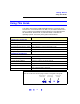
Getting Started Steps to Get Started Steps to Get Started This figure shows suggested steps to get started setting up LAN, USB, or GPIB interfaces and the applicable sections of this guide. Some guidelines follow this figure to select the interface you want to set up.
Getting Started Steps to Get Started ! Connect Instruments to LAN. A Local Area Network (LAN) provides instrument connectivity over distances and allows sequential sharing of instruments among multiple PCs. A LAN is the recommended method to connect instruments together in applications such as new test systems. If you select LAN connections, go to Connecting Instruments to LANs. ! Connect Instruments to USB. Universal Serial Bus (USB) is a quick and easy way to connect instruments to PCs on a benchtop.
Connecting Instruments to LANs ! LAN Quick Start ! ! ! ! Step 1: Select LAN Network Type Step 2: Gather Network Information Step 3: Connect Your Instruments Step 4: Install I/O Software on Your PC ! ! ! ! Step 5: Configure Your Instruments Step 6: Configure the LAN Interface Step 7: Communicate with Instruments Step 8: Program Your Instruments 11
Connecting Instruments to LAN LAN Quick Start LAN Quick Start This section shows suggested steps to help you quickly get started connecting and configuring your LAN-enabled instruments for site LAN or private LAN operation. What are Site LANs A site LAN network is defined as a local area network (LAN) in which and Private LANs? LAN-enabled instruments and Windows 98/2000/NT 4.0/Me/XP PCs are connected to a site LAN (workgroup LAN, Intranet, or enterprise LAN) via (optional) routers, hubs, and/or switches.
Connecting Instruments to LAN LAN Quick Start 1 Select LAN Network Type Select the type of LAN (site LAN or private LAN) to which you want to connect your instruments. Computer Site LAN Computer OR Private LAN Instrument Instrument Instrument Instrument 2 Gather Network Information Gather network parameters for site LAN connections or define private LAN parameters.
Connecting Instruments to LAN LAN Quick Start 5 Configure Your Instruments As required, manually configure your instruments using the instrument's Web Pages or front panel. You can use the Configuring Your Instrument Web Page to configure instruments. 6 Configure the LAN Interface Use IO Config to configure the TCPIP LAN Client interface. Then, add your instrument identifiers to the interface software. The TCPIP Devices dialog box lists devices present on the interface.
Connecting Instruments to LAN Step 1: Select LAN Network Type Step 1: Select LAN Network Type 1 Select LAN Network Type Select the type of LAN (site LAN or private LAN) to which you want to connect your instruments. Computer Site LAN OR Computer Instrument Private LAN Instrument Instrument Instrument What’s in This Step? The first step is to determine whether you want your instruments and your PC to be connected to a site LAN or to a private LAN.
Connecting Instruments to LAN Step 1: Select LAN Network Type Typical Site LAN Networks In this guide, a site LAN network is defined as a local area network (LAN) in which LAN-enabled instruments and Windows 98/2000/NT 4.0/Me/XP PCs are connected to a site LAN (workgroup LAN, Intranet, or enterprise LAN) via (optional) routers, hubs, and/or switches. This figure shows some example site LAN networks.
Connecting Instruments to LAN Step 1: Select LAN Network Type Typical Private LAN Networks In this guide, a private LAN network is defined as a local area network (LAN) in which LAN-enabled instruments and Windows 98/2000/NT 4.0/Me/XP PCs are NOT connected to a site LAN (workgroup LAN, Intranet, or enterprise LAN). This figure shows some example private LAN networks.
Connecting Instruments to LAN Step 2: Gather Network Information Step 2: Gather Network Information 2 Gather Network Information Gather network parameters for site LAN connections or define private LAN parameters.
Connecting Instruments to LAN Step 2: Gather Network Information Gather Site LAN Network Information Suggested steps follow to gather information for instrument connections to a site LAN. 1 Does the Site LAN Support DHCP? Find out if the site LAN supports Dynamic Host Configuration Protocol (DHCP). In general, if the site LAN supports DHCP, you can connect your instruments to site LAN without contacting your IT department.
Connecting Instruments to LAN Step 2: Gather Network Information Site LAN Network Information Card lnstrument Information (Completed by Instrument User) (Serial Number and Ethernet (MAC) Hardware Address usually on label on instrument) Instrument Serial Number: ______________________________ Ethernet (MAC) Hardware Address: ______________________________ Site LAN Information (Completed by System Administrator) Does the Network Support DHCP? If No, provide: Yes ___ No ___ IP Address (Static): ______.
Connecting Instruments to LAN Step 2: Gather Network Information Define Private LAN Network Parameters Suggested steps follow to define parameters for a private LAN. NOTE For a private LAN you, the designer of the LAN, are the “System Administrator” for the LAN and are responsible for defining all private LAN parameters. However, you may want to check with the System Administrator in your Information Technology (IT) department for guidelines on designing your private LAN.
Connecting Instruments to LAN Step 2: Gather Network Information Private LAN Network Information Card N E T W O R K DHCP Enabled: Yes ___ No ____ Dynamic DNS Enabled: Yes ___ No ____ UPnP Enabled OK: Yes ___ No ____ Subnet Mask: ______.______.______._____ DNS Server IP Address: ______.______.______._____ Hardware Address: ________________________ P C I N S T R U M E N T IP Address: ______.______.______._____ Subnet Mask: ______.______._____.______ DNS Server: ______.______._____.
Connecting Instruments to LAN Step 3: Connect Your Instruments Step 3: Connect Your Instruments 3 Connect Your Instruments Connect your instruments to the site LAN or private LAN you selected. To Site LAN PC Instrument What’s in This Step? This section gives guidelines to connect your instruments and LAN interface devices such as routers, hubs, or switches to site LANs or to private LANs. # To connect instruments to a site LAN, go to Connect Instruments to Site LAN.
Connecting Instruments to LAN Step 3: Connect Your Instruments Connect Instruments to Site LAN This section shows typical ways you can connect LAN-enabled instruments and interface devices such as routers, hubs, and switches to a site LAN. Two example network connections follow that you can use as templates to connect your instruments to the site LAN. Modify the connections as required for your application.
Connecting Instruments to LAN Step 3: Connect Your Instruments Example: Switch Connections (Site LAN) This figure shows one way to connect instruments to a site LAN via an Ethernet Hub or Switch. Ethernet Hub or Switch To Site LAN PC Standard CAT5 LAN Cable To LAN Port on Instruments Instrument Instrument Instrument Instrument 1 Turn Power OFF. Remove power from the instruments. 2 Connect Instruments to Hub/Switch.
Connecting Instruments to LAN Step 3: Connect Your Instruments Connect Devices to Private LAN This section shows typical ways you can connect LAN-enabled instruments and interface devices such as routers, hubs, and switches to a private LAN, assuming your PC is properly configured for LAN operation. Two example network connections follow that you can use as templates to connect your instruments to a private LAN. Modify the connections as required for your application.
Connecting Instruments to LAN Step 3: Connect Your Instruments Example: Switch Connections (Private LAN) This figure shows one way to connect a Windows 98/NT/2000/Me/XP PC and LAN-enabled instruments via an Ethernet hub or switch. Suggested connection steps follow. See hub/switch documentation for connections To Network Interface Card (NIC) Ethernet Hub or Switch PC Standard CAT5 LAN Cable To LAN Port on Instruments Instrument Instrument Instrument Instrument 1 Turn Power OFF.
Connecting Instruments to LAN Step 4: Install I/O Software on Your PC Step 4: Install I/O Software on Your PC 4 Install I/O Software on Your PC Select the I/O software to be installed on your PC. Then, install the software from a CD or from the Web. PC What’s in This Step? This step gives guidelines to install applicable I/O software on your PC. Go to Installing I/O Software for details. After the I/O software is installed, go to Step 5: Configure Your Instruments.
Connecting Instruments to LAN Step 5: Configure Your Instruments Step 5: Configure Your Instruments 5 Configure Your Instruments As required, manually configure your instruments using the instrument's Web Pages or front panel. You can use the Configuring Your Instrument Web Page to configure instruments. What’s in This Step? This may be an optional step. This step shows how to manually set TCP/IP parameters for LAN-enabled instruments, using the instrument’s Web Pages.
Connecting Instruments to LAN Step 5: Configure Your Instruments Check Your Web Browser If your instrument is Web-enabled, the instrument includes a Web Server you can access using a supported Web Browser (Internet Explorer 5.0 or higher). You can then use your Web Browser and the instrument’s Web Pages to view/modify network configuration parameters as required.
Connecting Instruments to LAN Step 5: Configure Your Instruments 2 View Current Configuration Page. To view the current configuration, click the View and Modify Configuration icon to display the Current Configuration Page. An example display for the 33220A follows.
Connecting Instruments to LAN Step 5: Configure Your Instruments 3 Display the Configuring the Instrument Page. From the Current Configuration Page, click the Modify Configuration box to display the Configuring the Instrument Page. You can then set/change instrument parameters as required 4 Set/Change TCP/IP Parameters. This figure shows a partial Configuring your 20MHz Function/Arbitrary Waveform Generator Page.
Connecting Instruments to LAN Step 6: Configure the LAN Interface Step 6: Configure the LAN Interface 6 Configure the LAN Interface Use IO Config to configure the TCPIP LAN Client interface. Then, add your instrument identifiers to the interface software. The TCPIP Devices dialog box lists devices present on the interface. What’s in This Step? This step gives guidelines to use the IO Config utility (installed as part of the Agilent IO Libraries) to configure the LAN interface.
Connecting Instruments to LAN Step 6: Configure the LAN Interface Steps to Configure the LAN Interface For an application that uses VISA (such as VISA Assistant) to communicate with instruments via the LAN, you must configure the TCPIP LAN Client interface by using the IO Config utility. Suggested steps to configure the TCPIP LAN Client interface follow. 1 Open the IO Config Utility.
Connecting Instruments to LAN Step 6: Configure the LAN Interface 3 Set LAN Client Parameters. When the LAN Client dialog box appears, in almost all cases, you can accept the default settings. If you need to change any items, click the Help button for an explanation of the items. Change items as required and then click the OK button to re-display the IO Config main screen. Click OK Typically, you can accept the default settings. 4 Re-Display LAN Client Dialog Box.
Connecting Instruments to LAN Step 6: Configure the LAN Interface 5 Display the TCPIP Devices Dialog Box. From the LAN Client dialog box, click the Edit VISA Config... button to display the TCPIP devices dialog box. Click the Edit VISA Config... button 6 Display the Add a TCPIP device Dialog Box. From the TCPIP devices dialog box, click the Add device button to display the Add a TCPIP device dialog box.
Connecting Instruments to LAN Step 6: Configure the LAN Interface 7 Enter Device IP Address/Hostname. From the Add a TCPIP device dialog box, enter either the IP address or hostname of the LAN instrument to be added and then click the OK button to re-display the TCPIP devices dialog box. For example, this dialog box adds a TCP/IP device at IP address 156.140.105.104. Click OK Enter IP Address 8 Display Devices Present. The TCPIP devices dialog box displays the TCP/IP devices present on the network.
Connecting Instruments to LAN Step 7: Communicate with Instruments Step 7: Communicate with Instruments 7 Communicate with Instruments You can use applications such as VISA Assistant or the Telnet utility to verify communication with instruments via the LAN. You can use VISA Assistant to verify communication with instruments. What’s in This Step? This section gives guidelines to communicate with your instruments using VISA Assistant.
Connecting Instruments to LAN Step 7: Communicate with Instruments Communicating Using VISA Assistant VISA Assistant is an application program that uses the Agilent IO Libraries to communicate with LAN, USB, and GPIB instruments. VISA Assistant can automatically detect and assign VXIplug&play instrument drivers to instruments. VISA Assistant can also be used to send and receive strings to instruments which support formatted I/O.
Connecting Instruments to LAN Step 8: Program Your Instruments Step 8: Program Your Instruments 8 Program Your Instruments This is an optional step. As desired, you can program instruments via the LAN using applications such as IVI-COM, VXIpnp, or VISA. VISA: viOpen (..."TCPIP0::instrumentHostName::INSTR"...) What’s in This Step? This is an optional step. After you have set up your site or private LAN, as desired you can program LAN-enabled instruments from your PC via the LAN.
Connecting Instruments to USB ! USB Quick Start ! Step 1: Install I/O Software on Your PC ! Step 2: Connect Instruments to USB ! Step 3: Assign Instrument Alias Name ! Step 4: Check Instrument Identification ! Step 5: Communicate with Instruments ! Step 6: Program Your Instruments 41
Connecting Instruments to USB USB Quick Start USB Quick Start This section shows suggested steps to help you quickly get started connecting USB-enabled instruments to the Universal Serial Bus (USB). NOTE Optionally, a USB hub may be connected between the PC and USB instrument(s). However, this configuration is not described in this guide. See your USB hub documentation if you use a USB hub.
Connecting Instruments to USB USB Quick Start 1 Install I/O Software on Your PC Select the I/O software to be installed on your PC. Then, install the software from a CD or from the Web. PC 2 Connect Instruments to USB Use USB cables to connect your instruments to the USB port(s) on your PC. USB Cable PC Instrument 3 Assign Instrument Alias Name As desired, assign each instrument's USB Alias name from the Assign USB device alias dialog box.
Connecting Instruments to USB USB Quick Start 4 Check Instrument Identification As desired, use IO Config to display the USB Devices dialog box. From this dialog box, you can check instrument identification parameters. This dialog box associates an instrument's USB Alias name with the instrument's Serial number, Vendor ID, Product ID, and Product Identification. 5 Communicate with Instruments You can use applications such as VISA Assistant to verify communication with instruments via the USB interface.
Connecting Instruments to USB Step 1: Install I/O Software on Your PC Step 1: Install I/O Software on Your PC 1 Install I/O Software on Your PC Select the I/O software to be installed on your PC. Then, install the software from a CD or from the Web. PC What’s in This Step? As required, you should install I/O software (such as the Agilent IO Libraries), on your PC before you connect instruments to USB. See Installing I/O Software for details. Then, go to Step 2: Connect Instruments to USB.
Connecting Instruments to USB Step 2: Connect Instruments to USB Step 2: Connect Instruments to USB 2 Connect Instruments to USB Use USB cables to connect your instruments to the USB port(s) on your PC. USB Cable PC Instrument What’s in This Step? This step shows how to connect USB Instruments to USB ports on your PC.
Connecting Instruments to USB Step 2: Connect Instruments to USB Steps to Connect USB Instruments Use the steps in this figure to directly connect USB instruments to a Windows 98(SE)/Me/2000/XP PC. If you have not yet installed I/O software on your PC, go to Installing I/O Software and install the software BEFORE you connect USB instruments to your PC. When you have made the connections for your system, go to Step 3: Set Instrument Alias Name.
Connecting Instruments to USB Step 3: Assign Instrument Alias Name Step 3: Assign Instrument Alias Name 3 Assign Instrument Alias Name As desired, set/change each instrument's USB Alias name from the Assign USB device alias dialog box. We recommend you choose a unique, meaningful USB Alias name and enter it in this dialog box. (If you do not assign the name now, you can change it later using IO Config.) What’s in This Step? This step shows how to assign an Alias name for USB instruments.
Connecting Instruments to USB Step 3: Assign Instrument Alias Name Assigning an Alias Name When you apply power to a USB instrument and then connect the USB cable between the instrument and your PC, an Assign USB device alias dialog box appears. From this dialog box, you can assign the instrument Alias name, as desired. NOTE When power is applied, a Found New Hardware dialog box may appear. If so, follow the on-screen instructions for installation advice. Then, return to this section.
Connecting Instruments to USB Step 4: Check Instrument Identification Step 4: Check Instrument Identification 4 Check Instrument Identification As desired, use IO Config to display the USB Devices dialog box. From this dialog box, you can check instrument identification parameters. This dialog box associates an instrument's USB Alias name with the instrument's Serial number, Vendor ID, Product ID, and Product Identification.
Connecting Instruments to USB Step 4: Check Instrument Identification Steps to Check Identification Parameters 1 Display the IO Config Main Screen. Click the blue IO icon (on the Windows Taskbar) and select Run IO Config to display the IO Config main screen. If there is no entry in the Configured Interfaces box for USB instruments, you can highlight USB *USB Instruments and click Configure to configure the USB interface. 2 Display the USB Devices Dialog Box.
Connecting Instruments to USB Step 5: Communicate with Instruments Step 5: Communicate with Instruments 5 Communicate with Instruments You can use applications such as VISA Assistant to verify communication with instruments via the USB interface. You can use VISA Assistant to verify communication with instruments. What’s in This Step? This is an optional step that gives guidelines to communicate with your instruments using VISA Assistant.
Connecting Instruments to USB Step 5: Communicate with Instruments Example: Communicating Using VISA Assistant VISA Assistant is an application program that uses the Agilent IO Libraries to communicate with LAN, USB, and GPIB instruments. VISA Assistant can automatically detect and assign VXIplug&play instrument drivers to instruments. VISA Assistant can also be used to send and receive strings to instruments which support formatted I/O.
Connecting Instruments to USB Step 6: Program Your Instruments Step 6: Program Your Instruments 6 Program Your Instruments This is an optional step. As desired, you can program instruments via the USB interface using applications such as IVI-COM, VXIpnp, or VISA. VISA: viOpen (...,"ArbGen",...) SICL: iopen ("ArbGen") What’s in This Step? This is an optional step. After you have set up your USB system, as desired you can program USB instruments from your PC via the USB interface.
Connecting Instruments to GPIB ! GPIB Quick Start ! Step 1: Install I/O Software on Your PC ! Step 2: Install GPIB Cards in Your PC ! Step 3: Connect Instruments to GPIB Card ! Step 4: Configure GPIB Interface Cards ! Step 5: Communicate with Instruments ! Step 6: Program Your Instruments 55
Connecting Instruments to GPIB GPIB Quick Start GPIB Quick Start This section shows suggested steps to help you quickly get started connecting GPIB instruments to the General Purpose Interface Bus (GPIB). Typical GPIB Interface System In this guide, a GPIB interface system is defined as a system in which GPIB instruments are connected to a GPIB interface card in a Windows 98/2000/ NT 4.0/Me/XP PC via GPIB cables.
Connecting Instruments to GPIB GPIB Quick Start 1 Install I/O Software on Your PC Select the I/O software to be installed on your PC. Then, install the software from a CD or from the Web. PC 2 Install GPIB Card(s) in Your PC As required, install one or more GPIB Interface Cards in your PC. 3 Connect Instruments to GPIB Card Connect your instruments to the installed GPIB Interface Card(s) using GPIB cables.
Connecting Instruments to GPIB GPIB Quick Start 4 Configure GPIB Interface Cards Use IO Config to configure installed GPIB Interface Card(s) parameters. You can use the GPIB Card Configuration dialog box to configure GPIB Interface Cards installed in your PC. 5 Communicate with Instruments You can use applications such as VISA Assistant to verify communication with instruments via the GPIB interface. You can use VISA Assistant to verify communication with instruments.
Connecting Instruments to GPIB Step 1: Install I/O Software on Your PC Step 1: Install I/O Software on Your PC 1 Install I/O Software on Your PC Select the I/O software to be installed on your PC. Then, install the software from a CD or from the Web. PC What’s in This Step? Before you connect your instruments to GPIB, as required install I/O software, such as the Agilent IO Libraries, on your PC. See Installing I/O Software for details. Then, go to Step 2: Install GPIB Cards in Your PC.
Connecting Instruments to GPIB Step 2: Install GPIB Cards in Your PC Step 2: Install GPIB Cards in Your PC 2 Install GPIB Cards in Your PC As required, install one or more GPIB Interface Cards in your PC. What’s in This Step? This step shows how to install GPIB Interface Cards (such as an Agilent 82350 PCI GPIB Interface for Windows) in your PC.
Connecting Instruments to GPIB Step 2: Install GPIB Cards in Your PC Steps to Install a GPIB Card in Your PC Example steps follow to install an Agilent 82350 PCI GPIB Interface Card for Windows in your PC. Modify the steps as required if you install a different GPIB Interface Card in your PC. When you have installed all required GPIB Interface Cards, go to Step 3: Connect Instruments to GPIB Card.
Connecting Instruments to GPIB Step 2: Install GPIB Cards in Your PC 3 Remove a Cover Plate. Remove one of the PC back panel cover plates. The 82350B is a 5V PCI card and will not fit in a 3.3V PCI slot or in an EISA or ISA slot. Choose a 5V PCI slot that will give adequate clearance for the GPIB connector. 4 Install the 82350. Insert the 82350 Interface Card edge connector into the PCI expansion slot connector of the PC.
Connecting Instruments to GPIB Step 2: Install GPIB Cards in Your PC 5 Replace the Cover Plate Screw. This will hold the 82350 in place. Save the blank cover plate for use if the 82350 is later removed. Replace the PC cover(s) as described in your PC documentation.
Connecting Instruments to GPIB Step 3: Connect Instruments to GPIB Card Step 3: Connect Instruments to GPIB Card 3 Connect Instruments to GPIB Card Connect your instruments to the installed GPIB Interface Card(s) using GPIB cables. GPIB Cable Instrument PC What’s in This Step? This step gives guidelines to connect GPIB instruments to a GPIB Interface Card (such as an Agilent 82350) installed in your PC by using GPIB cables.
Connecting Instruments to GPIB Step 3: Connect Instruments to GPIB Card Steps to Connect 1 Instruments to GPIB Cards Review Connection Guidelines. The recommended method for connecting a GPIB system is linear with the system controller (PC) at one end of the system.
Connecting Instruments to GPIB Step 3: Connect Instruments to GPIB Card # # # # # # # 10833A (1 meter) 10833B (2 meters) 10833C (4 meters) 10833D (0.5 meter) 8120-3448 (6 meters) 8120-3449 (8 meters) Other IEEE-488 GPIB interface bus cables, as applicable Example: Connecting a Single GPIB Instrument This figure shows connections from a single GPIB instrument to the GPIB connector of an Agilent 82350 GPIB Interface Card installed in your PC.
Connecting Instruments to GPIB Step 3: Connect Instruments to GPIB Card Example: Connecting Multiple GPIB Instruments This figure shows one way to connect three GPIB instruments to an Agilent 82350 GPIB Interface Card. You may want to record the primary GPIB address of each attached instrument for future programming use. After making the connections, reconnect the PC power cord and apply power to the PC and attached peripherals/instruments.
Connecting Instruments to GPIB Step 4: Configure GPIB Interface Cards Step 4: Configure GPIB Interface Cards 4 Configure GPIB Interface Cards Use IO Config to configure installed GPIB Interface Card(s) parameters. You can use the GPIB Card Configuration dialog box to configure GPIB Interface Cards installed in your PC.
Connecting Instruments to GPIB Step 4: Configure GPIB Interface Cards Steps to Configure GPIB Interface Cards 1 Apply Power. Apply power to the PC and to the installed GPIB instruments. As Windows 98/Me/2000/NT/XP restarts, a Found New Hardware Wizard may start. This figure shows a typical Windows 2000 display. The display may be different for other operating systems. 2 Install Configuration Files. Use this table for the actions to take for the operating systems listed.
Connecting Instruments to GPIB Step 4: Configure GPIB Interface Cards 4 Configure GPIB Card Parameters. When the 82350 PCI GPIB Card Configuration screen appears, set the VISA Interface Name, SICL Interface Name, Logical Unit and Bus Address values as required. Also, verify that this is the System Controller for the GPIB to which it is attached (this is the typical operating mode). (See the System Controller discussion.) Then, click the OK button. Some guidelines to set these values follow.
Connecting Instruments to GPIB Step 4: Configure GPIB Interface Cards NOTE After the system is configured, this screen may also display an Edit VISA Config... button. Clicking this button allows you to manually configure the interface as desired. 82350 GPIB Interface Card Configuration Parameters SICL Interface Name Symbolic name that SICL uses to uniquely identify this GPIB interface. The default Interface Name is gpib0.
Connecting Instruments to GPIB Step 4: Configure GPIB Interface Cards 5 Change/Accept the Configuration Values. If the configuration values displayed are acceptable to you, click the OK button. Otherwise, you can change the configuration values by clicking the arrows next to the values. If there are no arrows, you can change the configuration values by typing in the values you want.
Connecting Instruments to GPIB Step 5: Communicate with Instruments Step 5: Communicate with Instruments 5 Communicate with Instruments You can use applications such as VISA Assistant to verify communication with instruments via the GPIB interface. You can use VISA Assistant to verify communication with instruments. What’s in This Step? This step gives guidelines to communicate with your instruments using VISA Assistant.
Connecting Instruments to GPIB Step 5: Communicate with Instruments Example: Communicating Using VISA Assistant VISA Assistant is an application program that uses the Agilent IO Libraries to communicate with LAN, USB, and GPIB instruments. VISA Assistant can automatically detect and assign VXIplug&play instrument drivers to instruments. VISA Assistant can also be used to send and receive strings to instruments which support formatted I/O.
Connecting Instruments to GPIB Step 6: Program Your Instruments Step 6: Program Your Instruments 6 Program Your Instruments This is an optional step. As desired, you can program instruments via the GPIB interface using applications such as IVI-COM, VXIpnp, or VISA. VISA: viopen (..."GPIB0::5::INSTR"...) What’s in This Step? This is an optional step. After you have set up your GPIB system, as desired you can program GPIB instruments from your PC via the GPIB interface.
Connecting Instruments to GPIB Step 6: Program Your Instruments 76
Programming Your Instruments ! Programming Overview ! Addressing Instruments ! Example Programs 77
Programming Your Instruments Programming Overview Programming Overview This section provides an overview of programming instruments via LAN, USB, or GPIB interfaces. Four example programs are included to demonstrate generating a simple sine wave on an Agilent 33220A 20 MHz Function/Arbitrary Waveform Generator using Standard Commands for Programmable Instruments (SCPI). The example programs are written in Microsoft Visual Basic 6.
Programming Your Instruments Programming Overview Obtaining Instrument Drivers Selected combinations of program environments and I/O are included in the program examples in this guide. You will need to acquire the programming environment and the I/O independent of the Agilent IntuiLink for the 33220A Waveform Generator CD. ! Although not included in this guide, IDSK drivers are available and are installed as part of the free IntuiLink for Arb software included on this CD or may be obtained at http://www.
Programming Your Instruments Programming Overview Using I/O Objects in All Visual Basic programs in this guide use the Agilent VISA-COM object. Other Visual Basic To use the I/O object in another Visual Basic project, use these steps: Projects 1 Set the Reference. Set the reference to include the libraries in the Project/References menu: # "VISA COM 1.0 Type Library", corresponds to VISACOM.tlb # "Agilent VISA COM Resource Manager 1.0", corresponds to AgtRM.DLL # "VISA COM 488.2 Formatted I/O 1.
Programming Your Instruments Addressing Instruments Addressing Instruments This section gives guidelines to address instruments via a LAN, USB, or GPIB interface, including: ! Addressing Instruments via LAN ! Addressing Instruments via USB ! Addressing Instruments via GPIB Addressing Instruments via LAN To address instruments via the LAN, you must first configure the TCPIP LAN Client interface using the IO Config utility. A summary of the applicable LAN networking protocols follows.
Programming Your Instruments Addressing Instruments By default, the LAN Client supports both protocols by automatically detecting the protocol the server is using. When a VISA viOpen or SICL iopen call is performed, the LAN Client driver first tries to connect using the SICL-LAN protocol. If that fails, the driver will try to connect using the VXI-11 protocol. If you want to control the protocol used, you can configure more than one LAN Client interface and set each interface to a different protocol.
Programming Your Instruments Addressing Instruments Configuring TCPIP LAN Client Interfaces When you have configured VISA LAN Client interfaces, you can then use the interface name specified during configuration in a VISA viOpen call of your program. A summary of the steps to configure a TCPIP LAN Client interface follows. NOTE A single TCPIP LAN Client interface can be used by any number of VISA LAN Client interfaces.
Programming Your Instruments Addressing Instruments NOTE After the system is configured, this screen may also display an Edit VISA Config... button. Clicking this button allows you to manually configure the interface as desired. Example: Addressing LAN Instruments Using VISA/SICL The TCPIP LAN Client interface system in this figure consists of a Windows PC with a LAN (NIC) card and three LAN instruments. Instrument1 and instrument2 are VXI-11.2 (GPIB Emulation) instruments and instrument3 is a VXI-11.
Programming Your Instruments Addressing Instruments TCPIP LAN Client Addressing Interface VISA/SICL Names Windows PC LAN LAN Instruments instrument1 machine name 5 VXI-11.2 GPIB Emulation gpib0,5 1.2.3.4 IP address 3 VISA Name SICL Name VXI-11.2 GPIB Emulation gpib0,3 "TCPIP0" "lan" Network Interface Card instrument3 VXI-11.3 LAN instrument inst0 VISA/SICL Addressing (Using LAN Client) VISA: viOpen (... "TCPIP0::instrument1::gpib0,5::INSTR"...) viOpen (... "TCPIP0::1.2.3.
Programming Your Instruments Addressing Instruments Addressing Instruments via USB As desired, you can use an Alias name to address instruments via USB. The USB Alias name associates an alias with a specific instrument. You can use as a VISA rsrcName or SICL address instead of using the instrument’s Vendor ID, Product ID, Serial Number, and Interface Number. See the following steps to set, add, delete or change an Alias name. 1 Display the IO Config Main Screen.
Programming Your Instruments Addressing Instruments Example: Assigning a USB Alias Name This figure shows an example USB Devices dialog box for an Agilent 33220A. To change the USB Alias name, type the new name in the Alias name box and then click the OK button. The Alias name can be used as the preferred address for the VISA rsrcName and the SICL address. For this example, the Alias name has been changed to .ArbGen. from the default .UsbDevice1..
Programming Your Instruments Addressing Instruments Addressing Instruments via GPIB To address instruments via a GPIB interface, you must first configure the interface using the IO Config utility. Steps to Configure a Steps to configure a GPIB interface for an Agilent 82350 PCI card follow. Modify the steps as required if you use an 82341 ISA card.
Programming Your Instruments Addressing Instruments 2 When the 82350 PCI GPIB Card Configuration screen appears, set the VISA Interface Name, SICL Interface Name, Logical Unit and Bus Address values as required. Then, click the OK button. 3 If you have more than one 82350 card in your system, repeat for remaining cards. NOTE After the system is configured, this screen may also display an Edit VISA Config... button. Clicking this button allows you to manually configure the interface as desired.
Programming Your Instruments Addressing Instruments Example: Addressing GPIB Instruments Using VISA/SICL This figure shows example VISA and SICL addressing for GPIB instruments connected to a PC via a GPIB interface. GPIB (82350) Addressing Interface VISA/SICL Names Windows PC GPIB Cable GPIB Instruments 5 VISA Name SICL Name "GPIB0" "hpib7" 82350 GPIB Card #1 "GPIB1" "hpib8" 82350 GPIB Card #2 3 3 VISA/SICL Addressing VISA: viOpen (... "GPIB0::5::INSTR"...) viOpen (... "GPIB0::3::INSTR"..
Programming Your Instruments Example Programs Example Programs Four example programs follow to demonstrate sine waveform generation for an Agilent 33220A 20 Mhz Function/Arbitrary Waveform Generator. The example programs are essentially repeated to show the same functionality with different programming environments and I/O. See the Agilent IntuiLink for the 33220A Waveform Generator CD for other program examples.
Programming Your Instruments Example Programs ’ Other options are SQUare, RAMP, PULSe, NOISe, DC, and USER .WriteString "OUTPut:LOAD 50" ’ Set the load impedance in Ohms ’ (50 Ohms default) ’ May also be INFinity, as when using oscilloscope or DMM .WriteString "FREQuency 2500" .WriteString "VOLTage 1.2" ’ ’ ’ .WriteString "VOLTage:OFFSet 0.4" ’ Set the frequency. Set the amplitude in Vpp.
Programming Your Instruments Example Programs #include #include // Specify the default address #define DEFAULT_LOGICAL_ADDRESS OLESTR("GPIB0::10::INSTR") #import #import #import #import "IviDriverTypeLib.dll" no_namespace "IviFgenTypeLib.dll" no_namespace "VisaCom.tlb" no_namespace "Agilent33220.
Programming Your Instruments Example Programs psa = SafeArrayCreate (VT_I2, 1, &bounds); // Populate the safearray SHORT* Waveform; SafeArrayAccessData(psa, (void**) &Waveform); for (i = 1; i<= 16000; i++) { if(i < 14000) { Waveform[i-1] = (short)(sin(2.0 * pi * (double)Ncycles * (double)i / 14000) * 2047 * exp(Damp_factor * (double)i / 14000) + 0.5); } else { Waveform[i-1] = 0; } } SafeArrayUnaccessData(psa); // Download data points to volatile memory fprintf(stderr,"Downloading Arb...
Programming Your Instruments Example Programs Example: Simple Sine Waveform (Visual C++ and VXIpnp) This example program is intended for use with Microsoft Visual C++ 6.0 and requires VISA revision 2.0 and the Agilent Technologies 33220A VXIpnp instrument driver installed. This program shows how to download an arbitrary waveform using binary data. The program generates a damped sine wave using 16,000 points. #include #include #include #include #include "ag33250a.
Programming Your Instruments Example Programs /* Swap data bytes (send LSB first) */ CHECK(ag33250a_freq(vi, 5000)); /* Output frequency is 5 kHz */ CHECK(ag33250a_outpLoad(vi, ag33250a_OUTPUT_LOAD_50)); /* Output termination is 50 Ohms */ CHECK(ag33250a_volt(vi, 5)); /* Output amplitude is 5 Vpp */ fprintf(stderr, "Computing Waveform...\n"); /* Calculate data points */ for (i = 1; i<= 16000; i++) { if(i < 14000) { Waveform[i-1] = (short)(sin(2.
Programming Your Instruments Example Programs Example: Simple Sine Waveform (Visual C++ and VISA) This example program is intended for use with Microsoft Visual C++ 6.0 and requires VISA to be installed. This program uses the arbitrary waveform function to download and output a square wave pulse with a calculated rise time and fall time. The waveform consists of 4000 points downloaded to the function generator as ASCII data. #include #include #include #include
Programming Your Instruments Example Programs strcpy(SCPIcmd,"*CLS\n"); /* Clear errors and status registers */ CHECK(viWrite(Instrument, SCPIcmd, (ViUInt32)strlen(SCPIcmd), &actual)); /* Compute waveform */ fprintf(stderr, "Computing Waveform...\n"); strcpy(SCPIcmd, "DATA VOLATILE"); for(i = 1; i <= 5; i++) /* Set rise time (5 points) */ sprintf(SCPIcmd, "%s,%3.
Programming Your Instruments Example Programs strcpy(SCPIcmd, "FUNCtion:SHAPe USER\n"); /* Output the selected arb waveform */ CHECK(viWrite(Instrument, SCPIcmd, (ViUInt32)strlen(SCPIcmd), &actual)); strcpy(SCPIcmd, "OUTPut:LOAD 50\n"); /* Output termination is 50 Ohms */ CHECK(viWrite(Instrument, SCPIcmd, (ViUInt32)strlen(SCPIcmd), &actual)); strcpy(SCPIcmd, "FREQuency 5000;VOLTage 5\n"); /* Output frequency is 5 kHz @ 5 Vpp */ CHECK(viWrite(Instrument, SCPIcmd, (ViUInt32)strlen(SCPIcmd), &actual)); strcp
Programming Your Instruments Example Programs 100
Installing I/O Software ! Pre-Installation Checks ! Installing Your Software 101
Installing I/O Software Pre-Installation Checks Pre-Installation Checks Before you install I/O software on your PC, verify that your system meets the minimum hardware and software requirements to install and use the Agilent IO Libraries for the USB, LAN, or GPIB interface. Adding additional RAM may improve system performance. For example, this table shows minimum hardware and software requirements to install the software contained on the Agilent IntuiLink for the 33220A Waveform Generator CD.
Installing I/O Software Installing Your Software Installing Your Software Suggested steps follow to select and install I/O software for your application. 1 Determine Your Application Tasks. One way to select the I/O software for your application is to use the product life cycle approach. As shown in this figure, as the product life cycle moves from R&D to Manufacturing, tasks for the product typically change from Product Design to Product Characterization to Product Test.
Installing I/O Software Installing Your Software 2 Select Application and Agilent IO Libraries Software. The next step is to select the I/O software application(s) and Agilent IO Libraries version you want to install on your PC. This table gives guidelines for using IO software and Agilent IO Libraries version (developer or runtime). See substep 3, following, to select the Agilent IO Libraries version.
Installing I/O Software Installing Your Software 3 Select the Agilent IO Libraries Version. As noted, there are two versions of the Agilent IO Libraries: developer and runtime. Use the developer version if you want to communicate with instruments and to program instruments using VISA. Use the runtime version if you want to communicate with instruments, but do not need to program the instruments.
Installing I/O Software Installing Your Software For This Environment: Use This Media: That May Include: To Get This Media: Runtime (cannot program instruments) Instrument CD - Agilent IntuiLink - IVI-COM Drivers - VXIpnp Drivers - Agilent IO Libraries (runtime) - Agilent VEE evaluation copy Ships with the Instrument. Check the instrument CD to see which items are included on the CD. Web - Agilent IO Libraries (runtime) Download the libraries from www.agilent.
Troubleshooting Guidelines ! Troubleshooting LAN Interfaces ! Troubleshooting USB Interfaces ! Troubleshooting GPIB Interfaces 107
Troubleshooting Guidelines Troubleshooting LAN Interfaces Troubleshooting LAN Interfaces This section shows suggested troubleshooting steps for LAN interfaces, including the following items. For information on TCP/IP networks, see TCP/IP Network Basics. ! ! ! ! LAN Troubleshooting Overview Hardware Checks Communication Checks Web Browser Checks LAN Troubleshooting Overview LAN troubleshooting guidelines follow.
Troubleshooting Guidelines Troubleshooting LAN Interfaces Example: Using a Web Browser Since the 33220A is Web-enabled, to display the 33220A Welcome Page, first determine the 33220A IP address from the instrument’s front panel display. Next, open your web browser and type ‘http://<33220A IP Address>’, where <33220A IP Address> is the IP address displayed on the front panel. Then, press Enter to display the 33220A Welcome page. For example, if the current IP address is 169.254.3.2, typing http:// 169.254.
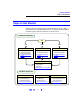
Troubleshooting Guidelines Troubleshooting LAN Interfaces Troubleshooting Flowchart If normal operation cannot be established, see this flowchart for suggested troubleshooting steps. We suggest you start at Hardware Checks. 1 Hardware Checks 2 Communication Checks 3 Web Browser Checks Typical Causes Typical Causes Typical Causes Bad cables/connections or power not ON for PC or instruments. Improper or Incorrect IP addresses and/or Hostnames Web Browser settings are incorrect.
Troubleshooting Guidelines Troubleshooting LAN Interfaces Hardware Checks The first step in troubleshooting LAN networks is to check the hardware setup for all devices connected to the LAN. This table shows some possible causes and corrective actions. After you have made the hardware checks and taken corrective actions as required, again check for normal operation as shown in Checking for Normal Operation. If normal operation has not been established, go to Communication Checks..
Troubleshooting Guidelines Troubleshooting LAN Interfaces Communication Checks If there are no hardware problems, but normal communication has not been established, the next step is to make communication checks using the ping command. In addition, for private LANs only, you may need to use the route add command to establish communication. If you can establish communication using these checks, but the web browser display is not correct, go to Web Browser Checks.
Troubleshooting Guidelines Troubleshooting LAN Interfaces A typical display follows where ping was not successful. Using the route add “If you are having difficulty with a private LAN (using a hub, switch, or even a simple crossover cable), a possible cause for no communication between Command the PC and connected instruments is that the PC has not recognized that it is connected to two different subnets. (See Local and Remote Networks for details.
Troubleshooting Guidelines Troubleshooting LAN Interfaces For example, if the IP address of your PC is 155.139.103.152 and the instrument address is 169.254.58.10, the two devices are probably on different subnets. To add the instrument to the subnet for the PC, use one of the following: ! route is lost when the PC is rebooted route add 169.254.58.10 155.139.103.152 or ! route persists when the PC is rebooted route -p add 169.254.58.10 155.139.103.
Troubleshooting Guidelines Troubleshooting LAN Interfaces Example: Setting Proxy Notification (Internet Explorer 5.0 and above) Example steps check proxy settings for Internet Explorer versions 5.0 and above follow. The steps are for Windows 2000. Modify the steps as required for other operating systems.
Troubleshooting Guidelines Troubleshooting LAN Interfaces Example: Cache and Page Refresh (Internet Explorer 5.0 and above) Example steps for cache and page refresh for Internet Explorer versions 5.0 and above follow. The steps are for Windows 2000. Modify the steps as required for other operating systems. 1 Click Start | Settings | Control Panel to display the Control Panel 2 From Control Panel, double-click Internet Options to display the Internet Properties dialog box.
Troubleshooting Guidelines Troubleshooting LAN Interfaces Enabling Javascript Instruments that are Web-enabled may generate web pages that depend on Javascript and Frames. For proper operation, you may need to enble Javascript. Example: Enabling Javascript (Internet Explorer 5.0 and above) Example steps for enabling Javascript for Internet Explorer versions 5.0 and above follow. The steps are for Windows 2000. Modify the steps as required for other operating systems.
Troubleshooting Guidelines Troubleshooting USB Interfaces Troubleshooting USB Interfaces This section shows suggested troubleshooting steps for Universal Serial Bus (USB) interfaces, including: ! USB Troubleshooting Overview ! USB Hardware Checks ! USB Software Checks NOTE The troubleshooting procedures in this section are primarily oriented toward USB instruments and the Agilent IO Libraries. Consult your instrument’s User’s Guide for troubleshooting details for the instrument.
Troubleshooting Guidelines Troubleshooting USB Interfaces USB Hardware Checks USB Software Checks Typical Causes Typical Causes No power on USB bus or hub or device turned off by Windows Plug and Play Manager. Agilent IO Libraries not installed or USB drivers not installed or improper IO Libraries operation.
Troubleshooting Guidelines Troubleshooting USB Interfaces USB Hardware Checks This section gives guidelines to make hardware troubleshooting checks for connected USB instruments. We suggest you start your troubleshooting sequence by performing the following hardware checks. If performing the hardware checks do not correct the problem, go to USB Software Checks.
Troubleshooting Guidelines Troubleshooting USB Interfaces USB Software Checks This section provides guidelines to make software troubleshooting checks for connected USB instruments. If you have not already done so, we suggest you start your troubleshooting sequence by performing the hardware checks in USB Hardware Checks. If performing the hardware and then the software checks does not correct the problem, contact Agilent for instructions. See Contacting Agilent for addresses.
Troubleshooting Guidelines Troubleshooting USB Interfaces 2 Install Agilent IO Libraries (as Required). If Version M.01.00 or greater of the Agilent IO Libraries is not installed on your PC, use this substep. Otherwise, skip to Verify USB Driver Installation. a Remove the USB cable from the USB port on the instrument. b Uninstall the IO Libraries from the Agilent IO Libraries Control (blue IO icon) c Re-attach the USB cable to the USB port on the instrument.
Troubleshooting Guidelines Troubleshooting USB Interfaces 2 Check IO Control Operation Uninstall/Reinstall the Agilent IO Libraries. If the driver files are not found, uninstall the Agilent IO Libraries by inserting the Instrument CD and following the instructions to remove the libraries. Then, install Version M.01.00 or greater of the Agilent IO Libraries. When the Agilent IO Libraries were installed, an IO Control was created.
Troubleshooting Guidelines Troubleshooting GPIB Interfaces Troubleshooting GPIB Interfaces This section shows suggested troubleshooting steps for an Agilent 82350 GPIB interface, including: ! ! ! ! GPIB Troubleshooting Overview GPIB Hardware Checks GPIB Software Checks Agilent IO Libraries Checks NOTE The troubleshooting procedures in this section are primarily oriented toward an Agilent 82350 GPIB card and the Agilent IO Libraries.
Troubleshooting Guidelines Troubleshooting GPIB Interfaces 1 GPIB Hardware Checks 2 GPIB Software Checks 3 IO Libraries Checks Typical Causes Typical Causes Typical Causes Bad GPIB cables/connections or power not ON for PC or instruments. GPIB card drivers not installed or GPIB card not properly configured.
Troubleshooting Guidelines Troubleshooting GPIB Interfaces GPIB Hardware Checks This section gives guidelines to make hardware troubleshooting checks for the GPIB card (such as an Agilent 82350), including: ! ! ! ! ! Check Cables/Connections/Power Check Device Manager If Sound Card Does Not Work If Data Transfers to Devices Fail If IO Config Finds 82350 Card with Serial Number ffffffff Check Cables/ We suggest you start your troubleshooting sequence by performing the Connections/Power following hardwar
Troubleshooting Guidelines Troubleshooting GPIB Interfaces Check Device Manager You can use the Windows Device Manager to reinstall the 82350 or equivalent, as required. For example, with Windows 2000, go to Control Panel by selecting Start | Settings | Control Panel. Then, select System | Hardware | Device Manager. From Device Manager, select 82350 and then Properties. Tab to Driver and click Reinstall Driver.
Troubleshooting Guidelines Troubleshooting GPIB Interfaces 3 If your computer locks up or freezes after installing. Typically, this is mostly interrupt conflicts with other drivers in the system. PCI allows sharing of IRQs, but this also means that the drivers for cards with which we are sharing an IRQ must be handling interrupt chaining properly. Both NT and Windows 9x allow multiple drivers to install interrupt service routines (ISRs) for a single IRQ.
Troubleshooting Guidelines Troubleshooting GPIB Interfaces 6 Upgrade your system BIOS. Note that even new computers may have a newer BIOS available. # Make sure the BIOS Installed O/S setting is set correctly. This determines what software will configure all the VXIplug&play cards in your system.
Troubleshooting Guidelines Troubleshooting GPIB Interfaces GPIB Software Checks This section provides guidelines for 82350 software checks, including: ! ! ! ! Check for 82350 Driver Files Check for 82350 Driver Files Disable IO Config Auto-Detection Check BIOS/Interrupts Settings Set 82350 Read/Write Performance Mode After installing the Agilent IO Libraries, check for installed 82350 driver files. 1 Check for 82350 Driver Files. Files are listed in their default directories.
Troubleshooting Guidelines Troubleshooting GPIB Interfaces Check BIOS/ Interrupts Settings If IO Config reports finding an 82350 card with Serial Number ffffffff, this is typically caused by PCI cards not properly configuring. Try the following steps. If these steps do not work, remove and re-install the 82350 and then reconfigure the card. 1 2 Check BIOS Setting. For Windows NT, make sure the BIOS Operating System setting is set to Not PnP OS or to Running Windows NT or to Other.
Troubleshooting Guidelines Troubleshooting GPIB Interfaces Right-click My Computer and select Properties, then Device Manager. Highlight Computer and click Properties. Find the 82350 card and check that all other cards on the same IRQ have a valid driver, not the big yellow question-mark. 4 Re-Configure Your PC. Configure your PC so as to not share IRQ lines. Many PCI cards have bugs when sharing IRQ lines. You may or may not be able to do this on all PCs.
Troubleshooting Guidelines Troubleshooting GPIB Interfaces # Interrupt. An entire buffer is transferred to/from the card without CPU involvement. Interrupt mode is advantageous for transferring large buffers because the higher per byte transfer rate more than compensates for the relatively long interrupt setup overhead. The default behavior of the 82350 driver is to use Polling mode for transfers of 256 bytes or less and to use Interrupt mode for larger transfers.
Troubleshooting Guidelines Troubleshooting GPIB Interfaces ! The default formatted IO write buffer size is 128 so when using this default size, formatted writes in SICL (with hint = I_HINT_DONTCARE) and VISA (with VI_ATTR_DMA_ALLOW_EN = VI_TRUE) will used Polling mode even when a large number of bytes are being sent. ! In SICL, Polling mode will always be used for the iread(), ifread() and iscanf() regardless of the above settings, when a termchr is set (itermchr() is not set to -1).
Troubleshooting Guidelines Troubleshooting GPIB Interfaces Agilent IO Libraries Checks This section gives guidelines to make troubleshooting checks for the Agilent IO Libraries, including: ! Check IO Libraries Installation ! Check IO Control Operation ! Install IO Libraries (if 82350 Was Installed First) Check IO Libraries Installation Start your Agilent IO Libraries troubleshooting sequence by verifying IO Libraries installation. If the IO Libraries are installed, go to Check IO Control Operation.
Troubleshooting Guidelines Troubleshooting GPIB Interfaces Check IO Control Operation When the Agilent IO Libraries were installed, an IO Control was created. When the IO Control is active, it is displayed as a blue IO icon on the Windows taskbar. If the IO Control is deactivated, SICL/VISA applications that are running with the 82350 will be unable to open sessions. By default, the IO Control is always active after the Agilent IO Libraries are installed and the blue IO icon is displayed.
Troubleshooting Guidelines Troubleshooting GPIB Interfaces # Windows 2000: The Found New Hardware Wizard will identify this card as a PCI Simple Communications Controller. The driver is typically located in the \Windows 2000 directory on the Instrument CD. # Windows NT 4.0: Since Windows NT is not a VXIplug&play OS, all necessary driver installation and configuration is performed when you install the Agilent IO Libraries.
Troubleshooting Guidelines Troubleshooting GPIB Interfaces 138
TCP/IP Network Basics ! LAN Interface Overview ! TCP/IP Protocols ! IP Addressing ! IP Address Configuration Methods ! Device Hostname Services ! Configuring Your PC for LAN Operation NOTE The information in this section is a summary of TCP/IP networks and LANs and is not intended to be a complete discussion of the subject. Consult standard reference texts for further details on TCP/IP and LANs.
TCP/IP Network Basics LAN Interface Overview LAN Interface Overview This section provides an overview of Local Area Networks (LANs) that use Transmission Control Protocol/Internet Protocol (TCP/IP), including: ! Typical Network Topologies ! LAN Hardware Architecture Typical Network Topologies LANs using TCP/IP can be divided into two categories: Site LANs and Private LANs. Site LAN Topology A Site LAN can be a workgroup LAN, Intranet, or enterprise (corporate) LAN.
TCP/IP Network Basics LAN Interface Overview Within the site LAN, every device (PC, router, server, etc.) is called a host. A host is any device on a network that has a TCP/IP address. TCP/IP addresses are called IP addresses, and each device on the network must have a unique IP address. A typical IP address for a device is 156.140.105.50. In general, communication within the Site LAN and to Private LANs is behind a firewall. Communication among devices on the Site LAN is controlled by routers.
TCP/IP Network Basics LAN Interface Overview LAN Hardware Architecture A LAN is a way to extend the control of instrumentation beyond the limits of typical instrument interfaces. You can communicate with instruments using a web browser, the Telnet utility, or sockets. However, to program (send SCPI commands) over the LAN, you must first configure the LAN interface using the Agilent IO Config utility provided with the Agilent IO Libraries.
TCP/IP Network Basics LAN Interface Overview Packet Switching A TCP/IP network is a packet-switched network. This figure shows an example packet-switched network. In this type of network, the computer that is sending the data (source host) breaks the data into smaller segments, called packets. Each packet is individually addressed and is sent to the destination (destination host.) The destination host then reassembles the packets into the original message.
TCP/IP Network Basics TCP/IP Protocols TCP/IP Protocols This section summarizes protocols for LAN networks that use TCP/IP for communication between hosts (devices such as computers, printers, and instruments), including: ! ! ! ! ! The TCP/IP Network Model The Network Interface Layer The Internet Layer The Transport Layer The Application Layer The TCP/IP Network Model The TCP/IP network model is based on protocols and an associated set of layers that control the actions of the network.
TCP/IP Network Basics TCP/IP Protocols TCP/IP Protocol Overview Layer Internet Transport This table summarizes the components of each layer and shows the applicable Request for Comments (RFC) for each component. Component Name Description Specification IP - Internet Protocol The lowest level protocol by which data are sent from one computer to another on the Internet.
TCP/IP Network Basics TCP/IP Protocols The Network Interface Layer The lowest layer in the TCP/IP stack is the Network Interface Layer. The primary responsibility of this layer is to define how a host device (computer, instrument, etc.) connects to the network. The Network Interface Layer acts as a host’s connection (interface) to the network. There are no TCP/IP protocols associated with the Network Interface layer. The Network Interface Layer is used to send and receive packets.
TCP/IP Network Basics TCP/IP Protocols The Internet Layer The Internet Layer of the TCP/IP model contains the protocols responsible for addressing and routing of packets. The Internet Layer includes several protocols, including: ! Internet Protocol (IP) ! Address Resolution Protocol (ARP) ! Internet Control Message Protocol (ICMP) For TCP/IP communications to be successful, the packet examined by the Network Interface Layer must include a hardware address.
TCP/IP Network Basics TCP/IP Protocols Example: Using ping for Echo Request For example, you could use the Ping utility to send ICMP echo request packets to the destination host and request the destination host return these packets. If the packets are returned, you can assume the connection is good. If the packets are not returned, a connectivity problem exists. This figure shows an example return from pinging a computer at IP address 156.140.72.1.
TCP/IP Network Basics TCP/IP Protocols As each packet is sent from the source host, an acknowledgement of receipt is sent by the destination host within a specified time. If the acknowledgement is not sent within this time, the sender re-sends the packet. If the receiver gets the packet in a damaged condition, the packet is discarded and the receiver sends no acknowledgement. In this case, since an acknowledgement was not received in the specified time, the sender resends the packet.
TCP/IP Network Basics TCP/IP Protocols The Application Layer The Application Layer is the layer where requests for data or services are processed. Applications at this layer are waiting for requests to process and all applications are “listening” at their respective port. The Application Layer has two protocols: ! File Transfer Protocol (FTP) ! Hypertext Transfer Protocol (HTTP) NOTE The Application Layer is not where an Internet browser, spreadsheet, etc. interact.
TCP/IP Network Basics TCP/IP Protocols Sockets For TCP/IP protocol, when a packet is delivered to a specific IP address, it is passed up to TCP or UDP and then to the appropriate host. This process forms a funnel through the TCP/IP stack, called a socket. A socket is uniquely defined by the IP address, the end-to-end protocol (TCP or UDP), and the port number. This figure shows typical socket architecture. When a socket is first created, it has an associated protocol but not an IP address or port number.
TCP/IP Network Basics TCP/IP Protocols File Transfer Protocol (FTP) File Transfer Protocol (FTP) is an application used to transfer files from a host to another host and store the files on the requesting host. In an FTP session, one host (the client) requests a file and the other host (the server) transfers a copy of the file to the client. The two hosts thus establish a client/server relationship. File transfer can be in text or binary format.
TCP/IP Network Basics IP Addressing IP Addressing This section describes IP addressing for TCP/IP networks, including: ! ! ! ! IP Address Classes Subnets and Subnet Masks Local and Remote Networks IP Address Configuration Methods IP Address Classes Each host on a TCP/IP network must have a unique address. This address is called the IP address and consists of a network portion and a host portion. The network portion and host portion of an IP address are determined by the subnet mask.
TCP/IP Network Basics IP Addressing NOTE Dot-notation addresses ("nnn.nnn.nnn.nnn" where "nnn" is a byte value) such as IP addresses must be expressed with care, as most web software on the PC will interpret byte values with leading zeros as octal numbers. Thus, "255.255.020.011" is actually equivalent to decimal "255.255.16.9" rather than "255.255.20.11" because ".020" is interpreted as "16" expressed in octal and ".011" as "9".
TCP/IP Network Basics IP Addressing Subnets and Subnet Masks As noted, an IP address consists of a network portion and a host portion. A subnet mask is a number that looks like an IP address that shows IP how many bits are used for the network portion of the IP address by “masking” the network portion of the IP address. Every IP address must have a subnet mask. You can use standard or custom subnet masks.To see how subnet masks are used, we will first define a subnet.
TCP/IP Network Basics IP Addressing Custom Subnet Masks You can create custom subnet masks for Class A, Class B, and Class C IP addresses. For example, for a Class A IP address, by using custom subnet mask 255.255.224.0 you can create 2,046 unique networks with 4,094 unique host on each network. A custom subnet mask adds more bits for the network portion of the IP address and uses fewer bits for the host portion of the IP address. These additional bits are called subnet bits.
TCP/IP Network Basics IP Addressing Local Network #1 (4 Hosts) Local Network #2 (4 Hosts) Computer D Computer A Router (Default Gateway) Instrument B Instrument E Instrument F Instrument C 157
TCP/IP Network Basics IP Address Configuration Methods IP Address Configuration Methods This section introduces some IP address configuration methods, including: ! ! ! ! Configuration Methods Overview Dynamic Host Configuration Protocol (DHCP) Auto-IP/ZEROCONF Duplicate IP Address Detection Configuration Methods Overview IP address configuration methods can be divided into two categories: automatic IP configuration and manual IP configuration.
TCP/IP Network Basics IP Address Configuration Methods Dynamic Host Configuration Protocol (DHCP) Dynamic Host Configuration Protocol (DHCP) allows each host on the network to be automatically assigned a unique IP address when the device is connected to a network that supports DHCP and is turned ON. To enable DHCP on a Site LAN, the System Administrator assigns a pool of IP addresses to a DHCP Server to be leased to hosts on the network. Each host on the network is called a DHCP Client.
TCP/IP Network Basics IP Address Configuration Methods Duplicate IP Addresses on nonDHCP Networks Generally, duplicate IP addresses only occur on a manually configured IP address network that does not use DHCP and Auto-IP/ZEROCONF. For example, a user may try to determine an IP address for a host by PINGing IP addresses on the network until an IP address is selected that does not respond. Based on this non-response, the user may assume the IP address is unused and assign it to their device.
TCP/IP Network Basics Device Hostname Services Device Hostname Services This section introduces some device Hostname services, including: ! ! ! ! Device Hostname Services Overview Dynamic DNS Naming RFC NetBIOS Naming Static DNS Naming Device Hostname Services Overview For ease of operation and communication on a TCP/IP network, you can assign a name to a host, called a hostname.
TCP/IP Network Basics Device Hostname Services Dynamic DNS Naming Dynamic Domain Name System (Dynamic DNS) is a distributed database of hostnames and associated IP addresses on the Internet. All hostnames on the Internet are divided into categories, called domains, such as .com, .edu, .org, etc. Dynamic DNS automatically provides hostnames and domain names for devices on networks that support Dynamic DNS.
TCP/IP Network Basics Device Hostname Services RFC NetBIOS Naming RFC NetBIOS Naming is a peer-to-peer naming protocol used by Microsoft File/Print Sharing that automatically provides hostnames for devices on networks that support RFC NetBIOS Naming. RFC NetBIOS naming uses a six-step process to resolve an IP address for a specified host name, as shown in the following figure. TCP/IP completes each step in the sequence shown before returning an error message.
TCP/IP Network Basics Device Hostname Services Static DNS Naming In contrast to automatic DNS name resolution, Static DNS naming does not require any host functionality to support dynamic methods of hostname resolution. Static DNS Naming uses a seven-step process to resolve an IP address to a specified hostname, as shown in this figure. TCP/IP completes each step in the sequence shown before returning an error message.
TCP/IP Network Basics Configuring Your PC for LAN Operation Configuring Your PC for LAN Operation This section shows steps to configure your PC, as required, for operation on a Private LAN or for operation on site LANs that do not support DHCP, including: ! ! ! ! ! Checking PC Settings Installing Network Interface Cards Installing TCP/IP on Your PC Setting PC IP Address Setting PC Hostname NOTE If your PC is part of an existing private LAN or site LAN, you probably do not need to do the steps in this se
TCP/IP Network Basics Configuring Your PC for LAN Operation Installing Network Interface Cards Network Interface Cards (NIC) provide the hardware interface between your PC and network devices such as routers, hubs, or switches. As required, install NIC(s) in your PC according to the NIC manufacturer’s instructions. Installing TCP/IP on Your PC To configure a network interface card, the TCP/IP protocol must be installed and configured.
TCP/IP Network Basics Configuring Your PC for LAN Operation Example: Installing TCP/IP (Windows XP) 1 Click Start | Network| Internet Connnections. From the “or pick a control panel icon”, select Network Connections. 2 Right-click Local Area Connection and then click Properties to display the Local Area Connection Properties dialog box. 3 The General tab should display Internet Protocol (TCP/IP). If not, click Install, then select Protocol and click Add.
TCP/IP Network Basics Configuring Your PC for LAN Operation Setting PC IP Address Depending on the LAN capabilities, you can select automatic or manual methods to set the IP address and the DNS Server address on your PC. These examples show how to set an IP Address for a Windows 2000 or Windows XP PC. Modify the steps as required for your operating system. NOTE You should not change the IP configuration of your PC unless you are sure this is necessary.
TCP/IP Network Basics Configuring Your PC for LAN Operation Example: Setting PC IP Address (Windows XP) 1 Click Start | Network| Internet Connnections. 2 From the “or pick a control panel icon”, select Network Connections. 3 Right-click Local Area Connection and then click Properties to display the Local Area Connection Properties dialog box 4 From the General tab, select TCP/IP Protocol and then click Properties.
TCP/IP Network Basics Configuring Your PC for LAN Operation Setting PC Hostname As desired, you can set an approved Hostname and a Domain Name (such as dept.company.com) for your PC. Examples for Windows 2000 and Windows XP follow. Modify the steps as required for your operating system. Example: Setting PC Hostname (Windows 2000) 1 Right-click the My Computer icon and then click Properties to display the System Properties dialog box.
TCP/IP Network Basics Configuring Your PC for LAN Operation Example: Setting PC Hostname (Windows XP) 1 Right-click the My Computer icon and then click Properties to display the System Properties dialog box. 2 Select the Network Identification tab and then click Properties to display the Identification Changes dialog box. 3 As required, set/change the Hostname and/or Domain Name. When you have finished, click the OK box to enable the assignments.
TCP/IP Network Basics Configuring Your PC for LAN Operation 172
Guide Information ! ! ! ! ! Guide Contents Related Documentation Accessing an Electronic Copy of This Guide General Information for This Guide Contacting Agilent 173
Guide Information Guide Contents This Agilent Technologies USB/LAN/GPIB Interfaces Connectivity Guide shows how to connect instruments to USB, LAN, and GPIB interfaces and how to configure and troubleshoot these interfaces on PCs with Windows 98, Windows Me, Windows NT 4.0, Windows 2000, or Windows XP operating systems. A summary of the guide contents follows. NOTE This guide does not describe LAN networks that include a gateway, such as the Agilent E5810A LAN/GPIB Gateway for Windows.
Guide Information Related Documentation Suggested related documentation you can use for interface connectivity operation follows. After the Agilent IO Libraries have been installed on your PC, .pdf files of the Agilent IO Libraries, VISA User’s Guide, and SICL User’s Guide are available. Click the blue IO icon on the Windows taskbar and then click View Documentation.
Guide Information General Information for This Guide Notice The information contained in this document is subject to change without notice. Agilent Technologies shall not be liable for any errors contained in this document. Agilent Technologies makes no warranties of any kind with regard to this document, whether express or implied. Agilent Technologies specifically disclaims the implied warranties of merchantability and fitness for a particular purpose.
Guide Information Contacting Agilent You can reach Agilent Technologies at these telephone numbers: Americas Call Center: Canada Call Center: European Call Center: Japan Call Center: 1-800-452-4844 1-877-894-4414 +31-20-547-9900 +81-426-56-7832 For other countries, contact your country’s Agilent support organization. A list of contact information for other countries is available on the Agilent Internet site: www.agilent.com/find/assist A list of other Agilent Websites follows. URL Description www.
Guide Information 178
Glossary 179
Glossary address - DHCP A address A string uniquely identifying a particular interface or a device on that interface to identify the interface or device. B Bridge In telecommunication networks, a bridge is a product that connects a local area network (LAN) to another local area network that uses the same protocol (for example, Ethernet or token ring).
Glossary DNS - Gateway IP Address Dynamic addressing simplifies network administration because the software keeps track of IP addresses rather than requiring an administrator to manage the task. This means that a new computer can be added to a network without manually assigning it a unique IP address. DHCP client support is built into Windows 98 and NT workstations. DNS Short for Domain Name System (or Service), an Internet service that translates domain names into IP addresses.
Glossary Hub - IP Address H Hub A common connection point for devices in a network. Hubs are commonly used to connect segments of a LAN. A hub contains multiple ports. When a packet arrives at one port, it is copied to the other ports so that all segments of the LAN can see all packets. - Passive hubs serve simply as a conduit for the data, enabling it to go from one device (or segment) to another.
Glossary LAN - logical unit L LAN Local Area Network. A computer network that spans a relatively small area. Most LANs are confined to a single building or group of buildings. However, one LAN can be connected to other LANs over any distance via telephone lines and radio waves. A system of LANs connected in this way is called a wide-area network (WAN). Most LANs connect workstations and personal computers.
Glossary network - network protocols N network A group of two or more computer systems linked together. There are many types of computer networks, including: local-area networks (LANs) : The computers are geographically close together (that is, in the same building). wide-area networks (WANs) : The computers are farther apart and are connected by telephone lines or radio waves. campus-area networks (CANs): The computers are within a limited geographic area, such as a campus or military base.
Glossary proxy server - proxy server DNS: See DNS FTP: Abbreviation of File Transfer Protocol, the protocol used on the Internet for sending files. HTTP: Short for HyperText Transfer Protocol, the underlying protocol used by the World Wide Web. HTTP defines how messages are formatted and transmitted, and what actions Web servers and browsers should take in response to various commands. ICMP: Short for Internet Control Message Protocol, an extension to the Internet Protocol (IP) defined by RFC 792.
Glossary Router - Subnet Mask R Router A device that connects any number of LANs. Routers use headers and a forwarding table to determine where packets go. They use Internet Control Message Protocol (ICMP) to communicate with each other and configure the best route between any two hosts. Very little filtering of data is done through routers. Routers do not care about the type of data they handle. Routers often have DHCP Server capability.
Glossary Switch - symbolic name For example, the full address for 150.215.017.009 is 10010110.11010111.00010001.00001001. The Class B network part is 10010110.11010111 and the host address is 00010001.00001001. If this network is divided into 14 subnets, the first four bits of the host address (0001) are reserved for identifying the subnet. The subnet mask is the network address plus the bits reserved for identifying the subnetwork.
Glossary Universal Plug and Play - VISA U Universal Plug and Play Universal Plug and Play (UPnP) is an open industry standard that uses Internet and Web protocols to enable devices such as PCs, peripherals, intelligent appliances, and wireless devices to be plugged into a network and automatically know about each other. UPnP is an architecture for pervasive peer-to-peer network connectivity of PCs and intelligent devices or appliances.
ABCDEFGHIJKLMNOPQRSTUVWXYZ Index A E (cont’d) address, 180 Address Resolution Protocol (ARP), 147 Agilent IntuiLink, 103 Agilent IO Libraries Control icon, 34, 69 Agilent websites, 177 Auto-IP/ZEROCONF, 159 B bridge, 180 C client, 180 Configuring the Instrument page, 32 connecting instruments to LANs, 11 controller, 180 copyright information, 176 crossover cable, 141 crossover point, 134 Current Configuration page, 31 D default gateways, 155 device, 180 DHCP, 159, 180 DNS, 181 domain, 162 dot-notation
ABCDEFGHIJKLMNOPQRSTUVWXYZ G H gateway, 181 gateway IP address, 181 getting started, 7, 9 glossary, 179 GPIB addressing instruments, 88 Agilent IO Libraries checks, 135 Bus Address, 71 cable connection guidelines, 65 check for driver files, 130 communicate with instrs, 73 configuration files, installing, 69 configure GPIB cards, 68 connect instruments, 64 crossover point, 134 definition, 56 Found New Hardware, 137 hardware checks, 126 install GPIB cards, 60 install software, 59 interrupt mode, 133 Logical
ABCDEFGHIJKLMNOPQRSTUVWXYZ L (cont’d) N LAN (continued) duplicate IP address detection, 159 enabling Javascript, 117 hardware architecture, 142 installing TCP/IP, 166 interface overview, 140 IP address classes, 153 IP addressing, 153 local and remote networks, 156 Network Interface Cards, install, 166 programming instruments, 40 quick start, 12 request for comments (RFC), 145 RFC NetBIOS Naming, 163 setting PC hostname, 170 setting PC IP address, 168 SICL-LAN protocol, 81 Static DNS Naming, 164 subnets an
ABCDEFGHIJKLMNOPQRSTUVWXYZ S (cont’d) U site LAN (continued) network info card, 20 sockets, 151 SRQ, 186 Static DNS Naming, 164 subnet, 186 subnet mask, 153, 186 switch, 141, 187 symbolic name, 187 Uniform Resource Locator, 152 Universal Plug and Play, 188 USB adressing instruments, 86 assign Alias name, 48 check instrument ID, 50 check USB driver files, 122 communicate with instrs, 52 connecting instruments, 46 definition, 42 hardware checks, 120 program your instruments, 54 quick start, 42 software che