
User`s guide

65
Connecting Instruments to GPIB
Step 3: Connect Instruments to GPIB Card
Steps to Connect
Instruments to GPIB
Cards
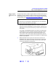
1 Review Connection Guidelines. The recommended method for
connecting a GPIB system is linear with the system controller (PC)
at one end of the system. However, a GPIB system can also be
connected together in a star, linear, or a combination configuration as
long as the total number of devices on the system is
≤15 and these
guidelines are followed:
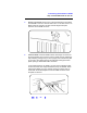
# To minimize stress on connector mountings, no more than
three cable connectors blocks should be stacked on top of
one another. The GPIB connector screws should be finger-
tightened only.
# Minimize cable length as much as possible. All system
devices must have tri-state drivers and must be powered on.
Systems with devices not using tri-state drivers are limited to
transfer rates <250 Kbytes/sec. Turning devices on or off
while a system is running may cause faulty operation.
# For operation with data transfer rates <500 Kbytes/sec, the
total length of all GPIB cables is
≤2 meters times the number
of devices connected together, up to a maximum of 20
meters.
# For operation with data transfer rates > 500 Kbytes/sec, the
total length of all GPIB cables is
≤1 meter times the number
of devices connected together, up to a maximum of 15
meters.
# The length between adjacent devices is not critical as long as
the overall restriction is met. GPIB bus extenders are
available that allow operation over much greater distances.
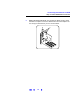
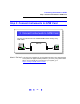
2
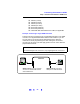
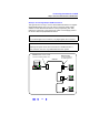
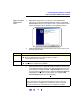
Connect GPIB Cables to the GPIB Interface Card. Connect a separate
GPIB cable to each installed GPIB Interface Card using one of the
following cables. Tighten the GPIB connector screws finger-tight only.
(The screwdriver slots are for removal purposes only.) Two example
connections follow connect a single GPIB instrument or to connect
multiple GPIB instruments.