Agilent E5810A LAN/GPIB Gateway for Windows® User’s Guide
THIS PAGE HAS BEEN INTENTIONALLY LEFT BLANK.
Front Matter Notice The information contained in this document is subject to change without notice. Agilent Technologies shall not be liable for any errors contained in this document. Agilent Technologies makes no warranties of any kind with regard to this document, whether express or implied. Agilent Technologies specifically disclaims the implied warranties of merchantability and fitness for a particular purpose.
Declaration of Conformity The Declaration of Conformity (DoC) for this instrument is available on the Agilent Web site. You can search the DoC by its product model or description at the Web address below. http://regulations.corporate.agilent.com/DoC/search.htm NOTE If you are unable to search for the respective DoC, please contact your local Agilent representative.
ICES Statement This ISM device complies with Canadian ICES-001. Cet appareil ISM est conforme à la norme NMB-001 du Canada. Regulatory Markings The CE mark is a registered trademark of the European Community. This CE mark shows that the product complies with all the relevant European Legal Directives. The C-tick mark is a registered trademark of the Spectrum Management Agency of Australia.
WARNINGS The following general safety precautions must be observed during all phases of operation, service, and repair of this product. Failure to comply with these precautions or with specific warnings elsewhere in this manual violates safety standards of design, manufacture, and intended use of the product. Agilent Technologies assumes no liability for the customer's failure to comply with these requirements.
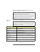
Documentation History All Editions and Updates of this manual and their creation date are listed below. The first Edition of the manual is Edition 1. The Edition number increments by 1 whenever the manual is revised. Updates, which are issued between Editions, contain replacement pages to correct or add additional information to the current Edition of the manual. Whenever a new Edition is created, it will contain all of the Update information for the previous Edition.
Corrective actions already tried (see Chapter 4 - Troubleshooting Information for suggested troubleshooting tips) Contacting Agilent You can reach Agilent Technologies at this telephone number in the Americas: Americas Call Center: 1-800-829-4444 For other countries, contact your country’s Agilent support organization. A list of contact information for other countries is available on the Agilent Internet site: www.agilent.com/find/assist A list of other Agilent Web sites follows.
Gateway for Windows that is connected to an Enterprise (corporate) network, to a Local Network, or directly to a PC. NOTE All Agilent IO Libraries information in this guide refers to Agilent IO Libraries Suite version 15.0 or above. For specific information on other versions of the Agilent IO Libraries or Agilent IO Libraries Suite, see the documentation for that version. You can download both updates and older versions (for backward compatibility) of the IO Libraries software at http://www.agilent.
Accessing an Electronic Copy of This Guide There are three ways you can access an electronic (.pdf) version of this guide, as follows. You will need Adobe Acrobat Reader Version 3.0 or later to view the electronic version. Access From the E5810A Web Access. After the E5810A is installed, you can access an electronic version of the manual by going to the Welcome page and clicking User’s Guide (under the E5810A Documentation heading). Access from the IO Control.
Table of Contents 1 E5810A Description E5810 Hardware Description ....................................................... 15 Typical Network Connections ............................................... 15 Front Panel Features ............................................................ 17 Rear Panel Features ............................................................ 21 Rack Mount Kit (Optional) .................................................... 21 E5810A Software/Firmware ................................
E5810A Support Information .................................................79 E5810A Documentation ........................................................80 Viewing and Modifying Configuration ...........................................81 Viewing E5810A Configuration .............................................81 Modifying E5810A Configuration ..........................................82 Finding and Querying Instruments ...............................................92 Finding Instruments ...............
1 E5810A Description
E5810A Description This chapter gives guidelines to install, configure, and troubleshoot the E5810A LAN/GPIB Gateway for Windows (E5810) for use with supported, network-equipped computer systems, including: E5810 Hardware Description E5810 Software/Firmware 14 Chapter 1
E5810A Description E5810 Hardware Description E5810 Hardware Description The E5810 LAN/GPIB Gateway for Windows provides a gateway between network-equipped computer systems and GPIB and/or RS-232 based instruments.
E5810A Description E5810 Hardware Description Local Network Connections Typically, a hub or switch is used for local network configuration. A cable/ DSL router may be used to provide a DHCP Server. For typical direct connections from a PC to the E5810, a crossover cable is connected from the E5810 LAN port to a LAN card on the PC. For Local Network or direct PC connections, the E5810 is not visible on the Enterprise network.
E5810A Description E5810 Hardware Description Front Panel Features This section describes the E5810 front panel features, NOTE The Hostname, if detected, is displayed on the first line of the E5810 front panel display. The IP Address of the E5810 is displayed on the second line of the E5810 front panel display. Front Panel Display/LEDs This figure shows E5810 front panel functions. Preset Button Depressing for <10 sec temporarily resets only the default password (E5810).
E5810A Description E5810 Hardware Description Typical Power-On Sequence This figure shows major steps in a typical power-on sequence for an E5810 that is connected to a network that supports Dynamic Host Configuration Protocol (DHCP) and Domain Name Service (DNS). If the network does not support DHCP and/or DNS, the power-on sequence may be different than that shown. Power Applied Display is blank, Power (Green) and Fault (Red) are ON.
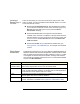
E5810A Description E5810 Hardware Description Power-On (Default) When power is first applied to the E5810 and the hardware self-test has completed, the E5810 is initialized to the factory-set default configuration. Settings This table shows the default configuration parameter settings for the E5810. The E5810 uses these default configuration values until you set any other configuration values. The E5810 also uses these values when you press the Preset button and hold it down for >10 seconds.
E5810A Description E5810 Hardware Description Depress and Quickly (<10 seconds) Release the Preset Button * - The E5810 password is temporarily reset to its factory default (E5810). All other configuration parameters remain unchanged. This state is maintained until the next time the E5810 is booted. The front panel display sequence is as follows. Hostname IP Address Temporary Password = "E5810" * Release the Preset button when Temporary Password = "E5810" is displayed.
E5810A Description E5810 Hardware Description Rear Panel Features This figure shows the rear panel features of the E5810. LAN Port Connect one end of a LAN patch cable to this port and connect the other end of the cable to a router/hub/switch. OR Connect one end of a crossover cable to this port and the other end of the cable to a LAN card on your PC. GPIB Port Connect one end of GPIB cable to this port and connect other end of cable to a GPIB instrument.
E5810A Description E5810A Software/Firmware E5810A Software/Firmware The E5810 LAN/GPIB Gateway for Windows provides an interface (gateway) that allows networked computers to talk or listen to GPIB and/or RS-232 devices via Local Area Network (LAN) connections. The E5810 connects a network (Enterprise or Local) from PCs with Windows XP/Vista/ 7/8/Server 2008 R2 to GPIB and/or RS-232 instruments.
E5810A Description E5810A Software/Firmware E5810A Operating Features Feature Description Remote access to instruments via LAN Access and control up to 14 GPIB and/or one RS-232 instrument via a 10BASE-T/100BASE-TX Ethernet. The E5810 detects the network and configures itself to the appropriate speed. The E5810 has a standard RJ-45 LAN connector. You can use adapters to connect other interface types, such as optical or wireless LAN.
E5810A Description E5810A Software/Firmware Typical Network Operation The E5810 provides a network gateway between network-equipped computer systems and GPIB and/or RS-232 based instruments. The gateway enables users to obtain measurement data either locally or remotely from GPIB and/or RS-232 instruments. See “Typical Network Connections” in this chapter for typical connections to Enterprise or Local Networks or to a PC.
E5810A Description E5810A Software/Firmware Software/Firmware Architecture To program instruments from your PC via the E5810 using a programming language such as C or Visual Basic, you must install and configure the Agilent IO Libraries Suite on the client PC. Client System Architecture As shown in the following figure, the client (PC) system contains the VISA LAN client software as well as the TCP/IP LAN software needed to access the E5810.
E5810A Description E5810A Software/Firmware How IO Application Software Works With the E5810 Before trying to perform an I/O application operation on the E5810 GPIB interface and the GPIB bus, the Remote IO Client software in the client computer system establishes a network connection to the remote I/O server (the E5810). Once the client establishes a connection, the client can begin to send I/O requests to the E5810.
E5810A Description E5810A Software/Firmware Typical Network IP Addressing This section describes typical Enterprise network IP addresses and subnet addresses on the network. This figure shows a typical Enterprise network, consisting of a Router (Gateway), a corporate Dynamic Host Configuration Protocol (DHCP) Server, and a subnet consisting of six hosts (two E5810s and four host PCs.) The Router sends packets of information to each host, based on the IP address of the host.
E5810A Description E5810A Software/Firmware Subnet Addressing A Subnet Mask is used to determine to which subnet an IP address belongs. An IP address has two components: the network address and the host address. For example, assuming IP address 156.215.117.109 is part of a Class B network, the first two numbers (156.215) represent the Class B network address and the second two numbers (117.109) identify a specific host on this network. See the Glossary for a description of a Class B network.
E5810A Description E5810A Software/Firmware Communicating with the E5810A There are two ways you can communicate with the E5810 via a network: use the E5810 Web access or use a supported programming language with the Agilent IO Libraries Suite. Using the E5810 Web Access Agilent IO Libraries Are Not Required PC LAN Use a supported Web Browser to access and configure the E5810. E5810 The E5810 provides a Web Server that allows for access via the Web.
E5810A Description E5810A Software/Firmware Using E5810 Web Access Since the E5810 is Web-enabled, you can communicate with the E5810 from a supported Web browser. The E5810 supports Internet Explorer 6.0 or greater. Typing in the E5810 IP address (or E5810 hostname, if known) on your Web browser address line and then pressing the Enter key displays the E5810 Welcome page. You can use the Web access to configure the E5810 and to communicate with GPIB and/or RS-232 instruments.
E5810A Description E5810A Software/Firmware Using a Supported Programming Language To use applications that require the Agilent IO Libraries, you must install and configure the Agilent IO Libraries Suite on each PC to be used for programming. Then, you can program connected instruments using a supported programming language (such as C or Visual Basic) using the Agilent Virtual Instrument Software Architecture (VISA), VISA COM, or Standard Instrument Control Language (SICL).
E5810A Description E5810A Software/Firmware Notes: 32 Chapter 1
2 Installing the E5810A
Installing the E5810A This chapter shows suggested steps to install the Agilent E5810A LAN/GPIB Gateway for Windows on LAN networks for Windows PCs, including: Installation Flowchart Before You Install the E5810A Getting Network Information Configuring the E5810A on a Local Network Installing the E5810A on an Enterprise Network Verifying Instrument Communication Installing and Configuring Agilent IO Libraries Suite NOTE All Agilent IO Libraries information in this guide refers to Agilent IO
Installing the E5810A Installation Flowchart Installation Flowchart This figure shows suggested steps to install and configure an E5810 on an Enterprise or Local network. See the next page for more details.
Installing the E5810A Installation Flowchart You can install the E5810 on an Enterprise (corporate) network that supports Dynamic Host Configuration Protocol (DHCP), an Enterprise network that does not support DHCP, or a Local network. NOTE If you plan to install the E5810 on an Enterprise network, contact your Information Technology (IT) Department to see if the network supports Dynamic Host Configuration Protocol (DHCP).
Installing the E5810A Before You Install the E5810A Before You Install the E5810A Before you connect the E5810A to a network, you should: Check Shipment Items Rack Mount the E5810A (Optional) Check Shipment Items In addition to this E5810 LAN/GPIB Gateway for Windows User’s Guide, your E5810 shipment should include the items shown in the following figure. If any items are missing or damaged, contact Agilent Technologies. See “Support Information” in the Front Matter of this guide for addresses.
Installing the E5810A Before You Install the E5810A Rack-Mount the E5810 (Optional) As desired, you can mount up to two E5810s in a single standard EIA rack space using the E5810 Rack Mount Kit (E5810 Option 100 or E5810-00100). The E5810 is one standard half-rack unit wide and one standard rack unit high. See the E5810-00100 Rack Mount Kit for installation instructions. NOTE You may want to configure the E5810 and ensure proper operation on the Enterprise or Local network before rack-mounting the unit.
Installing the E5810A Getting Network Information Getting Network Information This section gives guidelines to get information about Enterprise and Local networks, as applicable to your requirements. Getting Enterprise Network Information Before you connect the E5810 to an Enterprise (corporate) network, you will need to get some network configuration and network addressing parameters from the System Administrator in your Information Technology (IT) department.
Installing the E5810A Getting Network Information E5810 LAN/GPIB Gateway for Windows Network Information E5810 General Information (Completed by E5810 User) (Serial Number and Ethernet (MAC) Hardware Address on label on underside of E5810) Serial Number: ______________________________ Ethernet (MAC) Hardware Address: ______________________________ Default Values (for IT Department): DHCP: Enabled at power-on Hostname: No hostname configured Universal Plug&Play: Enabled Enterprise Network Informatio
Installing the E5810A Configuring the E5810A on a Local Network Configuring the E5810A on a Local Network This step gives guidelines to configure an E5810 on a Local network for eventual operation in a non-DHCP Enterprise network or in a Local network operation, including: What is a Local Network? Connecting the E5810 to a Local Network Configuring the E5810 on a Local Network NOTE This step gives guidelines to configure your E5810 on a Local network for eventual installation on an Enterprise networ
Installing the E5810A Configuring the E5810A on a Local Network Local Network Connections (Multiple PCs can Communicate with the E5810) LAN Patch Cable Typically Hub or Switch E5810 GPIB Instruments LAN GPIB RS232 GPIB GPIB GPIB To RS-232 Instrument GPIB Direct PC Connection (Only One PC can Communicate with the E5810) Crossover Cable GPIB Instruments E5810 LAN GPIB RS232 GPIB Connect to PC LAN Card GPIB To RS-232 Instrument GPIB GPIB 42 Chapter 2
Installing the E5810A Configuring the E5810A on a Local Network Connecting the E5810A to a Local Network This section shows how to connect the E5810 to a Local network using an Ethernet hub/switch or a crossover cable. E5810 Hub/Switch Connections This figure shows typical E5810 Ethernet hub or switch connections. Since the E5810 has no AC Power switch, the Mains disconnect for the E5810 is to unplug the AC power cord from the AC outlet.
Installing the E5810A Configuring the E5810A on a Local Network E5810 Crossover Cable Connections This figure shows typical E5810 connections using a crossover cable. Since the E5810 has no AC Power switch, the Mains disconnect for the E5810 is to unplug the AC power cord from the AC outlet. For this configuration, only one PC can communicate with the E5810. Typical E5810 Hardware Connections (Crossover Cable) Crossover Cable User-supplied crossover cable. Do NOT use LAN "patch" cable.
Installing the E5810A Configuring the E5810A on a Local Network Apply Power to the E5810 After connecting the E5810 to a Local network, plug the E5810 AC power cord into an AC outlet and observe the power-on sequence. When the power-on sequence is complete, the default IP address of the E5810 is displayed on the second line of the front panel display. A typical display follows. See Chapter 1, “E5810A Description” for power-on sequences. NOTE Local networks may not have a DHCP Server.
Installing the E5810A Configuring the E5810A on a Local Network Configuring the E5810A for Local Network Operation This section gives guidelines to configure the E5810 on a Local network. This section applies if you plan to configure the E5810 for eventual installation on a non-DHCP Enterprise network or plan to configure the E5810 for eventual use on the Local network.
Installing the E5810A Configuring the E5810A on a Local Network Configuring the You can check or set E5810 configuration parameters using the E5810 Web E5810 for Enterprise access that is accessed from your Web browser (Internet Explorer 6.0 or Network Operation greater). The steps to set E5810 configuration parameters are: 1 Display the Welcome Page.
Installing the E5810A Configuring the E5810A on a Local Network Click this icon 3 48 Display the Modify Configuration Page. From the Current Configuration of E5810 LAN/GPIB Gateway page, click the Modify Configuration button to display the Password dialog box.
Installing the E5810A Configuring the E5810A on a Local Network If the default password (E5810) is being used, the password is displayed as asterisks (*****). If not, type in the current password. Then, click the Submit button to display the Configuring Your E5810 LAN/GPIB Gateway page. 4 Set E5810 for Enterprise Network Operation.
Installing the E5810A Configuring the E5810A on a Local Network IP Address Assignment Enterprise Network Supports DHCP Enterprise Network Does Not Support DHCP No action required. The E5810 automatically receives an IP address from the network DHCP Server. Click DHCP OFF and enter the values provided by the System Administrator for IP Address, Subnet Mask, and Default Gateway IP Address.
Installing the E5810A Configuring the E5810A on a Local Network Example: Configuring the E5810 This example shows one way to set various E5810 parameters on the Configuring your E5810 LAN/GPIB Gateway page, assuming the Enterprise network to which the E5810 will be connected does not support DHCP or DNS. Since the network does not support DNS, a Hostname cannot be used for this E5810. In addition, it is assumed the network does not allow UPnP, so Universal Plug and Play is set to OFF. 2.
Installing the E5810A Installing the E5810A on an Enterprise Network Installing the E5810A on an Enterprise Network This step gives guidelines to install an E5810 on an Enterprise network. NOTE If your Enterprise network does not support Dynamic Host Configuration Protocol (DHCP), you must first configure your E5810 on a Local network as shown in “Configuring the E5810A on a Local Network” and then return to this step to install the E5810 on the Enterprise network.
Installing the E5810A Installing the E5810A on an Enterprise Network After connecting the E5810 to the Enterprise network, plug the E5810 AC power cord into an AC outlet and observe the power-on sequence. When the power-on sequence is complete, the assigned IP address of the E5810 is displayed on the second line of the front panel display. A typical display follows. See Chapter 1, “E5810A Description” for power-on sequences.
Installing the E5810A Installing the E5810A on an Enterprise Network For example, if the default IP address of 169.254.58.10 is displayed on the E5810 front panel, typing http://169.254.58.10 on your Web browser address line and pressing Enter displays the E5810 Welcome page. The following figure shows a typical display.
Installing the E5810A Installing the E5810A on an Enterprise Network 2 Display the Current Configuration Page. from the Welcome page, click the View & Modify Configuration icon to display the Current Configuration of E5810 LAN/GPIB Gateway page Click this icon 3 Display the Modify Configuration Page. From the Current Configuration of E5810 LAN/GPIB Gateway page, click the Modify Configuration button to display the Password dialog box.
Installing the E5810A Installing the E5810A on an Enterprise Network 56 Chapter 2
Installing the E5810A Installing the E5810A on an Enterprise Network 4 Set E5810 for DHCP Enterprise Network Operation. For an Enterprise network that supports DHCP, the only values you may need to set are the Hostname and Universal Plug and Play (UPnP) settings, as provided to you by your System Administrator, on the Configuring your E5810 LAN/GPIB Gateway page.
Installing the E5810A Verifying Instrument Communication Verifying Instrument Communication The last step in installing and configuring the E5810 is to verify communication from your PC to up to 14 connected GPIB instruments and/ or one RS-232 instrument via the E5810 Web access. See Chapter 3, “Using E5810A Web Access” for details. NOTE Over the Web, you can interact with instruments via your Web browser.
Installing the E5810A Verifying Instrument Communication Instrument Page Functions From the Find and Control Instruments Connected to your E5810 page, you can check instrument communication, send command/queries, and do other functions. Checking Instrument To check instrument communication, first select (highlight) the instrument to Communication be addressed by clicking the SICL Address in the Instruments Connected column.
Installing the E5810A Verifying Instrument Communication 3. Click the *IDN? button to identify the instrument 2. Select Instrument at SICL Address gpib0,22 4. Type command on Instrument Command line and then click Query 1. Click the Find button (as required) to display all connected instruments Where to Go Next 60 If you want to program instruments from your PC. Go to “Installing and Configuring Agilent IO Libraries Suite” on page 61. If you do not want to program instruments.
Installing the E5810A Installing and Configuring Agilent IO Libraries Suite Installing and Configuring Agilent IO Libraries Suite NOTE You must have Administrator privileges to install Agilent IO Libraries Suite Connection Expert. This section describes how to install the Agilent IO Libraries Suite on your PC. The Agilent IO Libraries Suite is a collection of libraries and utilities that gives you the ability to use your instruments from instrument control software.
Installing the E5810A Installing and Configuring Agilent IO Libraries Suite 4 62 Custom - Select the Custom installation to: a Install the IO Libraries Suite in another directory (for 32- bit operating systems only). b Save disk space by not installing interface manuals. c Use Agilent 32- bit VISA with another vendor's VISA on the same PC in side-by-side mode. Details on side-by-side mode are available at www.agilent.com/find/side-by-side-install or in the IO Libraries Suite help.
Installing the E5810A Installing and Configuring Agilent IO Libraries Suite Configuring a Remote GPIB Interface This section shows the steps to configure a remote GPIB interface, which is a logical interface on the client PC that supports communication with GPIB instruments on your E5810. If you do not have GPIB instruments connected to your E5810, but do have an RS-232 instrument connected, skip this section and go to “Configuring a Remote Serial Interface” on page 65.
Installing the E5810A Installing and Configuring Agilent IO Libraries Suite named TCPIP0 is configured when you start or refresh Connection Expert. To change timeouts and protocol properties for your remote interface, you must change the properties of this TCPIP interface. 5 If your E5810 is on a different subnet from your client PC, type the hostname or IP address of the E5810 in the Remote GPIB interface dialog box.
Installing the E5810A Installing and Configuring Agilent IO Libraries Suite Configuring a Remote Serial Interface This section shows the steps to configure a remote serial interface, which is a logical interface on the client PC that supports communication with RS-232 instruments on your E5810. If you do not have an RS-232 instrument connected to your E5810, skip this section and go to the next step, “Verifying Communication From Your PC” on page 68.
Installing the E5810A Installing and Configuring Agilent IO Libraries Suite 4 Specify the TCPIP interface that you wish to use to host this remote interface, in the TCPIP interface ID: field. This must be an interface that is already configured on your system; by default, a LAN interface named TCPIP0 is configured when you start or refresh Connection Expert. To change timeouts and protocol properties for your remote interface, you must change the properties of this TCPIP interface.
Installing the E5810A Installing and Configuring Agilent IO Libraries Suite 7 To establish communication with a serial instrument connected to your E5810, you will need to add this instrument manually in Connection Expert. (Connection Expert cannot auto-discover serial devices.) In the main Connection Expert window, click Add Instrument. In the Add Instrument dialog box, select the remote serial interface that you just added and click OK.
Installing the E5810A Installing and Configuring Agilent IO Libraries Suite Verifying Communication From Your PC This section gives guidelines to communicate with and to program connected GPIB and RS-232 instruments from your PC via the E5810, including: Using Interactive IO for Communication Using Supported Programming Languages NOTE You can also communicate with (but not program) installed GPIB and/or RS-232 instruments using the E5810 Web access, whether or not you have installed and configured the
Installing the E5810A Installing and Configuring Agilent IO Libraries Suite 3 *IDN? is the default command. Click Send & Read to send the identification query to the instrument and display its reply in the Interactive IO window. 4 To send other commands, click Commands> to select from a list of common commands, or type a command into the Command: field. If you experience timeout errors for some commands, click Options to change the timeout value.
Installing the E5810A Installing and Configuring Agilent IO Libraries Suite For information on programming using Agilent VISA, see the Agilent VISA User’s Guide. Also see the Agilent Connectivity Guide and Agilent IO Libraries Suite Online Help for further information and guidelines on programming with the Agilent IO Libraries.
Installing the E5810A Installing and Configuring Agilent IO Libraries Suite Addressing Instruments with SICL SICL addresses include the IP address or hostname of your E5810 as well as the SICL address of the device on the E5810, and optionally the protocol to be used. Some example addresses for SICL programs follow. These examples assume that the SICL interface ID of your TCPIP interface is “lan”.
Installing the E5810A Installing and Configuring Agilent IO Libraries Suite Notes: 72 Chapter 2
3 Using E5810A Web Access
Using E5810A Web Access This chapter gives guidelines on how to use E5810A Web access, including: 74 Opening Your Web Browser for E5810A Web Access Using the Welcome Page Viewing and Modifying Current Configuration Finding and Querying Instruments Other Web Access Functions Chapter 3
Using E5810A Web Access Opening Your Web Browser for E5810A Web Access Opening Your Web Browser for E5810A Web Access Since the E5810 is Web-enabled, you can access and communicate with the E5810 using your Web browser (Internet Explorer 6.0 or greater).
Using E5810A Web Access Using the Welcome Page Using the Welcome Page This section shows the features of the E5810 Welcome page, including the following items. A typical Welcome page display follows.
Using E5810A Web Access Using the Welcome Page Navigation Bar Clicking the applicable icon on the Navigation Bar on the left side of the page allows you to take the actions shown in the following figure. Welcome Page Displays the Welcome page. View & Modify Configuration Displays the Current Configuration of E5810 LAN/GPIB Gateway page. From this page, you can view current E5810 configuration parameters.
Using E5810A Web Access Using the Welcome Page E5810A Current Settings The Current Settings part of the Welcome page displays some of the current settings for the E5810. A typical display follows. See “E5810 Configuration Parameter Descriptions” in this chapter for detailed descriptions. Ethernet (MAC) Address A unique address assigned by the manufacturer for each Internet device. The Ethernet address is on a label on the underside of the E5810.
Using E5810A Web Access Using the Welcome Page E5810A Support Information E5810 support information includes Support, Products, and Agilent Site as listed on the banner on the top of the page. NOTE These links attempt to access the Agilent Web site. Depending on your network configuration, these links may not be accessible (networkdependent message). Support Connects you to the Contact Us Web page.
Using E5810A Web Access Using the Welcome Page E5810A Documentation You can click Help to access a complete E5810 help system or click User’s Guide to display the E5810 LAN/GPIB Gateway for Windows User’s Guide. Help Clicking Help displays the contents page of the E5810 help system and allows you to access E5810 help.
Using E5810A Web Access Viewing and Modifying Configuration Viewing and Modifying Configuration This section shows how to view and modify (as required) the current configuration of the E5810 using the Current Configuration of E5810 LAN/GPIB Gateway and the Configuring your E5810 LAN/GPIB Gateway page. Viewing E5810A Configuration To begin modifying the E5810 current configuration, click the View & Modify Configuration icon to display the Current Configuration of E5810 LAN/GPIB Gateway page.
Using E5810A Web Access Viewing and Modifying Configuration Modifying E5810A Configuration To modify the current E5810 configuration, from the Current Configuration of E5810 LAN/GPIB Gateway page, click the Modify Configuration button at the top or the bottom of the page to display the Password dialog box. Displaying the If the default password (E5810) is set as the current password, asterisks Configuration Page (*****) appear in the window.
Using E5810A Web Access Viewing and Modifying Configuration Chapter 3 83
Using E5810A Web Access Viewing and Modifying Configuration E5810 Configuration An alphabetical listing of E5810 configuration parameter descriptions and Parameter applicable default (factory-set) values follows. The E5810 uses the default Descriptions configuration values until you change any value and save/reboot. The E5810 also uses the default values when you press and hold down the Preset button for >10 seconds. Parameter [Default] Description Default Gateway [0.0.0.
Using E5810A Web Access Viewing and Modifying Configuration Parameter [Default] Domain Name Server (DNS) (cont) [0.0.0.0] Description A DNS Server is an Internet service that translates domain names into IP addresses. Every time you use a domain name, a DNS server must translate the name into the corresponding IP address. For example, the domain name www.example.com might translate to 198.105.232.4. The DNS system is distributed.
Using E5810A Web Access Viewing and Modifying Configuration Parameter [Default] Description Dynamic Host Configuration Protocol (DHCP) [ON] (cont’d) DHCP OFF: If DHCP is OFF or unavailable, during startup the E5810 will use the static IP address that may be input in the Configuring your E5810 LAN/GPIB Gateway page. In this case, the values for the IP Address, Subnet Mask, and Default Gateway shown in the Configured Value column of the page will be used during startup.
Using E5810A Web Access Viewing and Modifying Configuration Parameter [Default] Hostname [None] Description This value configures the internet domain name for the E5810. Hostnames are useful when IP addresses are being assigned by a DHCP Server, since the Hostname will not change despite DHCP Server changes and device IP address changes. If a Hostname is entered, the E5810 will try to register this name when it boots. The E5810 can only register the Hostname if the network has Dynamic DNS.
Using E5810A Web Access Viewing and Modifying Configuration Parameter [Default] IP Address [169.254.58.10] Description This value is the Internet Protocol (IP) address of the E5810. The IP address is a required value and is used for all IP and TCP/IP communications with the E5810. The IP address is represented in dotted decimal notation (for example, 154.140.222.201). This number is assigned by the System Administrator. The E5810 has a default static IP address of 169.254.58.10.
Using E5810A Web Access Viewing and Modifying Configuration Parameter [Default] Password [E5810] Description E5810 configuration and instrument control pages are passwordprotected against changes. To change from the default password (or any password) to a new one, enter the current (old) password in the Configured Value column and enter the new password in both boxes in the Edit Configuration column of the Configuring your E5810 LAN/GPIB Gateway page. The default password is “E5810”.
Using E5810A Web Access Viewing and Modifying Configuration Parameter [Default] Description RS-232 Parity [NONE] Parity is used by the RS-232 hardware to verify data transmission. The Parity value is dependent on the peripheral device you connect to the RS-232 port. Check the documentation for your peripheral device to set this value. Available parity check options for the E5810 are NONE, ODD, EVEN, SPACE and MARK.
Using E5810A Web Access Viewing and Modifying Configuration Parameter [Default] Universal Plug & Play (UPnP) [ON] Description If Universal Plug & Play (UPnP) is enabled, a multicast message is generated and sent about once an hour to the subnet. Enterprise (corporate) networks will want to decide whether this additional traffic is acceptable. By default, UPnP is NOT enabled on Windows XP. Check your Operating System instructions to enable UPnP. Universal Plug and Play (UPnP) has two options: ON or OFF.
Using E5810A Web Access Finding and Querying Instruments Finding and Querying Instruments This section shows how to find and query GPIB and/or RS-232 instruments connected to your E5810 by using the Find and Control Instruments Connected to your E5810 page. This page is password-protected since you can inadvertently interfere with running VISA/SICL applications if you query an instrument at an inappropriate time.
Using E5810A Web Access Finding and Querying Instruments Finding Instruments The Instruments Connected column of the page shows the GPIB and/or RS-232 instruments connected to your E5810. This column shows the SICL address for each instrument connected. The SICL address is required for programmatically interacting with instruments via the E5810. Using the Find Button To refresh the display or if instruments have been added/deleted, click the Find button to display the current configuration.
Using E5810A Web Access Finding and Querying Instruments Querying Instruments After you have successfully found all connected instruments, you can use the Control Panel for Selected Instrument column of the page to interact with the instruments. There are two ways to interact with connected instruments: use the buttons at the top of the column or use the Instrument Command line at the bottom of the column.
Using E5810A Web Access Finding and Querying Instruments Button Description *IDN? ID String. Returns the ID string for the selected IEEE-488.2 compliant instrument. Device Clear Device Clear. Sometimes communication with an instrument may be impeded. This can occur for a wide variety of reasons. Sending a Device Clear to the instrument usually solves this problem and restores proper communication with the instrument.
Using E5810A Web Access Finding and Querying Instruments Querying Instruments Using the Instrument Command Line For supported instruments, you can also query an instrument by first highlighting the instrument in the Instruments Connected column, typing in a SCPI command (such as meas:volt:dc?) on the Instrument Command line, and then clicking Send and Receive, or Query. To send a command to the instrument without waiting for a response, click the Send button.
Using E5810A Web Access Other Web Access Functions Other Web Access Functions This section describes four other E5810A Web Access functions: Determining Session Status Using Web Help Updating E5810A Firmware Determining Session Status To open the E5810 LAN/GPIB Gateway Status page, click the Session Status icon on the Navigation Bar. A typical display follows. Click the Refresh button to update the display to the current configuration.
Using E5810A Web Access Other Web Access Functions Using Web Help Clicking Help (under E5810 Documentation) displays the Contents page of the E5810 Web Access Help system from which you have full access to the entire help system. The Contents page display follows. Note that your specific Windows toolbar appears at the top of the display for ease of navigation, printing, etc. Also, you can access a topic either from the Table of Contents on the left side or from the Contents listing on the page.
Using E5810A Web Access Other Web Access Functions Updating E5810A Firmware This section gives guidelines to update your E5810 firmware to the latest version. NOTE Do not update your E5810 firmware unless you have a specific need to do so, such as defect repair or instrument enhancements. If the firmware update fails, the E5810 reverts to its original firmware version. The E5810 uses standard FTP (File Transfer Protocol) to perform updates.
Using E5810A Web Access Other Web Access Functions Agilent FTP site is Accessible From E5810 1 Verify the E5810 is Idle. Updating the E5810 is a significant activity. Be sure no other user or program is using the E5810 before you attempt to update the firmware. You can check the number of open sessions by displaying the E5810 LAN/GPIB Gateway Status page. To open this page, click the Session Status icon on the Navigation Bar.
Using E5810A Web Access Other Web Access Functions 4 Perform Firmware Update a Click the Update Firmware button to display a password dialog box. Click OK to confirm the update and the E5810 will attempt to download the firmware from the FTP site. b After you confirm the update, the E5810 front panel should display the message “Updating firmware…” c The LAN LEDs should light, indicating LAN activity is taking place. The firmware for the E5810 is approximately 5.
Using E5810A Web Access Other Web Access Functions 2 Install FTP Server, if Needed. You will need to access a standard FTP Server program. See “Troubleshooting Guidelines” in this section for tips to access a standard FTP Server. 3 Set up User Account Information for FTP Server. Refer to the FTP Server documentation on creating a user account and a password. The user account is used for the login name. 4 Copy E5810 Firmware Image to FTP Directory.
Using E5810A Web Access Other Web Access Functions 7 Configure FTP Parameters and Filename. Enter the following information in the dialog box: a Firmware FTP Server Hostname or IP Address: Enter the IP address of the FTP Server (e.g., 192.6.143.21) OR enter the FTP Server domain name, if a DNS Server is available and configured in the E5810 (e.g., ftp.agilent.com) b User Login: Enter the Login name for the FTP Server (same as Step 3) (e.g.
Using E5810A Web Access Other Web Access Functions c The LAN LEDs should light, indicating LAN activity is taking place. The firmware for the E5810 is ~ 5.1 MB. Download time may vary, depending on network connections. d After the firmware image has been downloaded into the E5810, the E5810 will automatically reboot and display a “Rebooting E5810...” message. The E5810 then begins a normal startup sequence. 9 Troubleshooting Guidelines Verify Firmware Revision.
Using E5810A Web Access Other Web Access Functions 2 If the Update was Unsuccessful. If the last message in the system log indicates the E5810 was trying to update firmware, the firmware process was not successful and the E5810 firmware will revert to its original (factory-set) version. In this case, try the following: a Verify FTP Server Address. Verify that the Firmware FTP Server domain name is correct and fully qualified. A domain name is a symbolic name for an IP address. For example, 'ftp.agilent.
Using E5810A Web Access Other Web Access Functions Notes: 106 Chapter 3
4 Troubleshooting Information
Troubleshooting Information This chapter gives guidelines to troubleshoot problems that may occur with the E5810A LAN/GPIB Gateway for Windows, including: Troubleshooting Overview Checking the E5810A Checking the Network Checking PC Client Connections Checking Instruments NOTE There are no user-serviceable parts in the E5810 LAN/GPIB Gateway for Windows. If you suspect a hardware failure in the E5810, contact Agilent Technologies for procedures to return the device.
Troubleshooting Information Troubleshooting Overview Troubleshooting Overview This figure shows a typical network configuration using the E5810 and shows suggested sequence of steps to troubleshoot the system to determine if the cause is with the client PC, with the network, with the E5810, or with connected instruments.
Troubleshooting Information Checking the E5810A Checking the E5810A This section gives guidelines to check the E5810A, including: Checking Front and Rear Panel Displays Checking E5810A Configuration Parameters Checking Front and Rear Panel Displays As a first step in troubleshooting the system, you should check the front panel display and LED status. In addition, you can check the rear panel Ln LED to see if there is communication from your PC to the E5810 via the LAN.
Troubleshooting Information Checking the E5810A LED Status Possible Cause(s) Corrective Action(s) POWER and LAN ON (blinking LED), GPIB and/or RS232 OFF during instrument activity Indicates communication via the LAN to the E5810, but not to connected GPIB and/or RS-232 instruments. Check GPIB and/or RS-232 connections and configuration. Make sure instrument power is turned ON.
Troubleshooting Information Checking the E5810A Error Message Description The E5810 tried to use an IP address that is currently being used by another device on the network. Try these actions: ERROR: IP in use Reboot the E5810 with the Preset button depressed to set the E5810 back to booting with DHCP enabled. OR Remove other device(s) from the network and reboot the E5810 OR Move the E5810 to a Local network, disable DHCP, and set the E5810 to an unused IP Address.
Troubleshooting Information Checking the E5810A Checking E5810A Parameters If the front panel display and LEDs indicate no error conditions, check the E5810 configuration parameters. Checking E5810 If the E5810 is connected to an Enterprise (corporate) network, you can Current Parameters check the E5810 current settings displayed on the Configuring your E5810 LAN/GPIB Gateway page against the Enterprise Network Information provided to you by your System Administrator.
Troubleshooting Information Checking the Network Checking the Network If the E5810 is correctly installed and configured and is operational, the next step is to check the network installation and configuration. To do this step, you may need the help of your System Administrator. This section gives guidelines to check your network.
Troubleshooting Information Checking the Network Checking Web Browser Settings The E5810 Web access (web server) generates web pages that depend on Javascript and Frames. You can use any web browser that supports these features to view and interact with the E5810 web server. For best results, you may need to Enable Javascript, and configure Cache and Page Refresh, and/or Proxies options on your Web browser. Internet Explorer 6.0 or greater is recommended.
Troubleshooting Information Checking the Network Doing this usually causes the browser to first look in its cache to see if the page exists. If the page is cached, the browser displays the page from the cache instead of going to the network to update changes. Since the E5810 web pages are dynamic in nature, the cache may contain content that is outdated on modern browsers.
Troubleshooting Information Checking the Network Steps to Set Proxy Notification (Microsoft Internet Explorer 5.0, 5.5) 1 From Internet Explorer, select Tools->Internet Options 2 Click the Connections tab 3 Click the LAN Settings… button under Local Area Network (LAN) settings 4 Under Proxy server, if “Use a proxy server” is checked, click the Advanced… button 5 Under Exceptions, add the IP address of the E5810 or a fullyqualified domain name (such as myE5810.example.
Troubleshooting Information Checking the Network SICL Timeout Set to 0 (infinite) The E5810 uses the LAN maximum timeout configured in Connection Expert’s LAN interface for its default or infinite timeout. If a SICL itimeout(id,0) command is used (where a 0 timeout value is an infinite timeout) the E5810 will use the I/O Timeout (sec): value set on the Current Configuration of E5810 LAN/GPIB Gateway page. The default timeout value is 120 sec.
Troubleshooting Information Checking PC Client Connections Checking PC Client Connections Even if the E5810 has been successfully configured and the configuration has been verified, individual PC clients may still have problems connecting to the E5810.
Troubleshooting Information Checking PC Client Connections Example: Using the To send a ping command from your PC to an E5810, open the MS-DOS ping Command window. For example, on Windows 2000, click Start | Programs | Accessories | Command Prompt. When the MS-DOS window opens, type ping , where is the IP address of the E5810, and press the Enter key. A typical display follows.
Troubleshooting Information Checking PC Client Connections Checking syslog Messages The syslog messages can be viewed by typing /systemLog.htm on your web browser, where is the IP address of the E5810. For example, if the IP address of the E5810 is 169.254.58.10, type http://169.254.58.10/systemLog.htm to display the message table.
Troubleshooting Information Checking PC Client Connections syslog Messages The following table lists common syslog messages generated by the E5810. NOTE The Telnet Utility is the ONLY way to clear syslog messages. When the syslog message queue is full, new messages will not be accepted and will not overwrite existing syslog messages. See Appendix B, “Using the Telnet Utility” for steps to clear syslog messages.
Troubleshooting Information Checking PC Client Connections Message Description ERROR: Firmware Update: FTP server not found Could not find FTP server specified. ERROR: Firmware Update: Invalid User Login or Password Login or Password is invalid for the FTP server. ERROR: Firmware Update: Data not received from FTP Server Could not receive data from the FTP Server. May be trying to access FTP server through a firewall. ERROR: Firmware Update: Invalid file or directory Could not find file.
Troubleshooting Information Checking PC Client Connections Runtime Error Messages Common runtime errors that may occur in your programs when using an E5810 are described in the following table, where “viopen” is a VISA open command. Message Description/Actions viopen fails: Invalid address errors Use the E5810 Welcome page on your Web browser to verify that the GPIB address, GPIB interface name, and/or GPIB logical unit configuration values are correct. Or, you can use Connection Expert.
Troubleshooting Information Checking PC Client Connections Message Description/Actions viopen fails or I/O operation fails: Out of resources The E5810 was unable to open another session or perform the operation because it is out of resources. You may need to have a client terminate its connection or you may need to reboot the E5810 to close all client connections to reclaim resources. Rebooting will disconnect all other users accessing the E5810.
Troubleshooting Information Checking PC Client Connections Message Description/Actions E5810 appears to be hung There are several possible causes. For all of the following, use of client timeouts and/or E5810 timeouts (the I/O timeout and LAN timeout configuration values) can be used to ensure that the E5810 will not “hang” indefinitely.
Troubleshooting Information Checking Instruments Checking Instruments This section gives guidelines to check connected GPIB and RS-232 instruments, including: Checking GPIB Instruments Checking RS-232 Instruments Checking GPIB Instruments If you cannot establish communication with connected GPIB instruments, see the following table for suggested troubleshooting steps.
Troubleshooting Information Checking Instruments Checking RS-232 Instruments If you cannot establish communication with a connected RS-232 instrument, see the following table for suggested troubleshooting steps. Possible Cause(s) Corrective Action(s) Attempting to Communicate From the E5810 Web Access Intermittent or missing RS-232 connection Check RS-232 cable connections. Verify that the RS-232 cable is the correct cable for this application.
A E5810A Specifications
E5810A Specifications This appendix lists E5810 LAN/GPIB Gateway for Windows technical specifications, supplementary information, and supported network protocols.
E5810A Specifications Specifications and Supplementary Information Specifications and Supplementary Information General Requirements Minimum System Requirements for Agilent IO Libraries Suite Windows XP SP3/Windows Vista/Windows 7 (with or without SP1)/Windows 8/Windows Server 2008 R2 (with or without SP1) 600 MHz or higher (1 GHz 32-bit recommended for Windows Vista, Windows 7, Windows 8, and Windows Server 2008 R2[1]), 256 MB RAM (1 GB or greater for Windows Vista, Windows 7, Windows 8, and Windows Ser
E5810A Specifications Specifications and Supplementary Information Environmental Specifications Operating Environment 0oC to 55oC - Indoor use, Pollution Degree 2 Installation Category II (mains input) Altitude (operating) 3000 meters Operating Humidity up to 95% R.H. @40oC Environmental Specifications (cont’d) Storage Humidity up to 90% R.H.
E5810A Specifications Specifications and Supplementary Information Supplementary Information GPIB Modes of Operation Supported The E5810 supports all standard GPIB modes of operation. IEEE-488.1 and IEEE-488.2 Compliance The E5810 is in full compliance with IEEE-488.1 and IEEE488.2 specifications. The E5810 fully supports IEEE-488.1 subsets AH1, C1, C2, C3, C4, C27, DC0, DT0, LE3, PP0, RL0, SH1, SR0, and TE7.
E5810A Specifications Supported Network Protocols Supported Network Protocols The E5810 uses the network IP and Ethernet protocols listed in the following table. See the Glossary for a definition of these protocols.
B Using the Telnet Utility
Using the Telnet Utility This appendix explains how to access and exit the Telnet utility. It also summarizes various Telnet commands you can use with the E5810 LAN/GPIB Gateway for Windows.
Using the Telnet Utility Using the Telnet Utility Using the Telnet Utility For backward compatibility with the E2050 LAN/GPIB Gateway, the Telnet Utility functionality is provided with the E5810. However, E5810 Web Access is the preferred method to configure the E5810. Accessing the Telnet To access the Telnet utility: Utility 1 If you are on a Windows XP computer system, do the following: From the Windows XP taskbar, select Start | All Programs | Accessories|Command Prompt. The MS-DOS window opens.
Using the Telnet Utility Using the Telnet Utility Exiting the Telnet Utility To exit the Telnet utility, use these Telnet commands. If you want to exit without saving any changes (if any) you have made to the configuration values, at the Telnet prompt (>) type bye (or) exit (or) quit. If you want to save the changes you have made to the configuration values via the Telnet utility, at the Telnet prompt (>) type reboot.
Using the Telnet Utility Using the Telnet Utility Typical Telnet Screen Display A typical display screen for an E5810 follows. The configuration values you see for your E5810 will probably be different from those shown. Welcome to the E5810 LAN/GPIB Gateway Configuration Utility.
Using the Telnet Utility Telnet Commands for the E5810A Telnet Commands for the E5810A This table lists the Telnet commands you can use with the E5810. You should use the Telnet configuration commands only if you are using the Telnet configuration method to configure the E5810.You can see a summary of all Telnet commands online by typing ? at any time within the Telnet utility. NOTE The Telnet utility is the ONLY way to clear syslog messages.
Using the Telnet Utility Telnet Commands for the E5810A Command Description gpib-name View/Set the GPIB SICL Interface Name gpib-address <0-30> View/Set the GPIB System Controller Address gpib-unit <1-255> View/Set the GPIB Logical Unit Number rs232-name View/Set the RS-232 SICL Interface Name rs232-baud View/Set Baud Rate <300|1200|2400|4800|9600| 19200|38400|57600|115200> rs232-bits <5|6|7|8> View/Set number of RS-232 data Bits rs232-stopbits <1|2> View/Set number o
Using the Telnet Utility Telnet Commands for the E5810A Notes: 142 Appendix B
Glossary 143
Glossary A address A string uniquely identifying a particular interface or a device on that interface which is interpreted at the E5810 LAN/GPIB Gateway to identify the interface or device. ASRL For the E5810, ASRL is synonymous with RS-232. See RS-232. B bridge C client In telecommunication networks, a bridge is a product that connects a local area network (LAN) to another local area network that uses the same protocol (for example, Ethernet or token ring).
DHCP Short for Dynamic Host Configuration Protocol, a protocol for assigning dynamic IP addresses to devices on a network. With dynamic addressing, a device can have a different IP address every time it connects to the network. In some systems, the device's IP address can even change while it is still connected. DHCP also supports a mix of static and dynamic IP addresses.
G gateway Hardware that permits a network connection between the LAN that your computer understands and the instrument specific interface that your device understands. Gateway IP Address This parameter is the IP Address of the default subnet gateway that allows the E5810 to communicate with systems that are not on the local subnet. Thus, this is the default subnet gateway where packets are sent that are destined for a device not on the local subnet, as determined by the subnet mask setting.
I instrument A device that accepts commands and performs a test or measurement function. interface A connection and communication media between devices and controllers, including mechanical, electrical, and protocol connections. IP address An Internet Protocol (IP) address is an identifier for a computer or device on a TCP/IP network. Networks using the TCP/IP protocol route messages based on the IP address of the destination.
L LAN Local Area Network. A computer network that spans a relatively small area. Most LANs are confined to a single building or group of buildings. However, one LAN can be connected to other LANs over any distance via telephone lines and radio waves. A system of LANs connected in this way is called a wide-area network (WAN). Most LANs connect workstations and personal computers.
N network protocols The E5810 supports these network protocols: ARP, DHCP, DNS, FTP, HTTP, ICMP, and RPC. ARP: Short for Address Resolution Protocol, a TCP/IP protocol used to convert an IP address into a physical address (called a DLC address), such as an Ethernet address. DHCP: See DHCP DNS: See DNS FTP: Abbreviation of File Transfer Protocol, the protocol used on the Internet for sending files. HTTP: Short for HyperText Transfer Protocol, the underlying protocol used by the World Wide Web.
Instead of forwarding the request to the Web server where Page 1 resides, which can be a time-consuming operation, the proxy server returns the Page 1 it already fetched for user X. Since the proxy server is often on the same network as the user, this is a much faster operation. Real proxy servers support hundreds or thousands of users. Filter Requests: Proxy servers can also be used to filter requests.
SRQ Service Request. An asynchronous request (an interrupt) from a remote device indicating that the device requires servicing. subnet A portion of a network that shares a common address component. On TCP/IP networks, subnets are defined as all devices whose IP addresses have the same prefix. For example, all devices with IP addresses that start with 100.100.100. would be part of the same subnet. Dividing a network into subnets is useful for both security and performance reasons.
switch A device that filters and forwards packets between LAN segments. Switches operate at the data link layer (layer 2) and sometimes the network layer (layer 3) of the OSI Reference Model and therefore support any packet protocol. LANs that use switches to join segments are called switched LANs or, in the case of Ethernet networks, switched Ethernet LANs. A hub connects all the devices on its “ports” together.
Option OFF: The E5810 is not UPnP capable and will not announce its presence as a UPnP device when mounted to the network. V VEE The Agilent Visual Engineering Environment, which is software used for I/ O application programming. VISA The Agilent Virtual Instrument Software Architecture library, which is software used for I/O application programming. Agilent VISA is part of the Agilent IO Libraries Suite. VISA COM A COM (Common Object Model) implementation of VISA.
Notes: 154 Glossary
Index A address, 144 Agilent IO Libraries Suite check for installed version, 61 Agilent Web sites, 8 Agilent, contacting, 8 ASRL, 144 B bridge, 144 C cache and page refresh, 115 cleaning instructions, 108 Clear ALL Pending Operations button, 94 Clear History button, 94 client, 24, 144 contacting Agilent, 8 controller, 144 copyright information, 7 D Declaration of Conformity, 4 default gateway, 84 defaults,resetting, 113 description, 84 device, 144 Device Clear button, 94 DHCP, 86, 145 DNS, 145 documentat
Using the Instruments Page, 96 Using the ping Command, 120 Using VISA Assistant, 68 VISA LAN Client Addressing, 70 F Find button, 93 finding instruments, 92, 93 Friendly Name, 145 G gateway, 146 gateway IP address, 146 glossary, 144 GPIB address, 86 GPIB logical unit, 86 GPIB SICL Interface Name, 86 H hardware address, 86 hostname, 87, 146 hub, 146 I ID string (*IDN?) button, 94 instrument, 147 instruments, finding, 92, 93 instruments, programming, 69 instruments, querying, 92, 94 interface, 147 IO time
RS232 Flow Control, 89 RS232 Parity, 90 RS232 SICL Interface Name, 90 RS232 SRQ, 90 RS232 Stop Bits, 90 runtime error messages, 124 S safety, 5 serial number, 86 server, 24, 150 session status, determining, 97 SICL, 150 SICL timeout set to 0, 118 software/firmware architecture, 25 specifications, 131 SRQ, 151 Subnet, 151 subnet mask, 27, 90, 151 support information, 7 switch, 152 symbolic name, 152 syslog messages, 121 SYST ERR? button, 94 User Guide, electronic copies, 10 User Guide, information, 8 V VE
THIS PAGE HAS BEEN INTENTIONALLY LEFT BLANK.
www.agilent.