LC Devices Agilent 1200 Series Getting Connected Guide XCALI-97250 Revision A January 2009
© 2009 Thermo Fisher Scientific Inc. All rights reserved. Agilent is a registered trademark of Agilent Technologies Inc. LCQ, LTQ, LXQ, MSQ, and TSQ are trademarks and Xcalibur is a registered trademark of Thermo Fisher Scientific Inc. in the United States. Thermo Fisher Scientific Inc. provides this document to its customers with a product purchase to use in the product operation.
C Contents Preface . . . . . . . . . . . . . . . . . . . . . . . . . . . . . . . . . . . . . . . . . . . . . . . . . . . . . . . . . . . . . . .v About This Guide. . . . . . . . . . . . . . . . . . . . . . . . . . . . . . . . . . . . . . . . . . . . . . . . v Related Documentation . . . . . . . . . . . . . . . . . . . . . . . . . . . . . . . . . . . . . . . . . . . v Safety and Special Notices . . . . . . . . . . . . . . . . . . . . . . . . . . . . . . . . . . . . . . . . .vi Safety Precautions. . . . . .
Contents Chapter 6 Setting Up the Instrument Method to Trigger Data Acquisition. . . . . . . . . . . . . .31 Chapter 7 Vial and Well Locations for the Available Tray Types. . . . . . . . . . . . . . . . . . . . . .33 40-Vial Trays. . . . . . . . . . . . . . . . . . . . . . . . . . . . . . . . . . . . . . . . . . . . . . . . . . . 34 100-Vial Trays. . . . . . . . . . . . . . . . . . . . . . . . . . . . . . . . . . . . . . . . . . . . . . . . . . 35 54-Vial Plates . . . . . . . . . . . . . . . . . . . . .
P Preface About This Guide This guide describes how to set up the Agilent 1200 Series LC system to trigger data acquisition from a Thermo Scientific mass spectrometer and how to connect the Agilent 1200 Series LC system to the data system computer through an Ethernet connection. Related Documentation The Xcalibur data system provides Help for the Agilent 1200 Series devices from within the Instrument Setup view of the program.
Preface Safety and Special Notices Make sure you follow the precautionary statements presented in this guide. The safety and other special notices appear in boxes. Safety and special notices include the following: CAUTION Highlights hazards to humans, property, or the environment. Each CAUTION notice is accompanied by an appropriate CAUTION symbol. CAUTION Highlights electric shock related hazards to human beings. Each electric shock notice is accompanied by the international High Voltage symbol.
Preface Contacting Us There are several ways to contact Thermo Fisher Scientific for the information you need. Y To contact Technical Support Phone Fax E-mail Knowledge base 800-532-4752 561-688-8736 us.techsupport.analyze@thermofisher.com www.thermokb.com Find software updates and utilities to download at mssupport.thermo.com. Y To contact Customer Service for ordering information Phone Fax E-mail Web site 800-532-4752 561-688-8731 us.customer-support.analyze@thermofisher.com www.thermo.
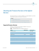
1 Checking the Firmware Versions of the Agilent Devices This chapter describes how to check the compatibility of your Agilent 1200 Series system with the device drivers provided on the LC Devices software CD. Contents • Supported Firmware Versions • Checking the Firmware Versions with the Agilent Instant Pilot • Checking the Firmware Versions from the Xcalibur Data System Supported Firmware Versions LC Devices 2.2.
1 Checking the Firmware Versions of the Agilent Devices Checking the Firmware Versions with the Agilent Instant Pilot Checking the Firmware Versions with the Agilent Instant Pilot You can use the Agilent Instant Pilot to check the firmware versions of the Agilent 1200 Series modules to ensure their compatibility with the device drivers provided with LC Devices. Y To check the firmware version of an Agilent 1200 Series module 1.
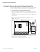
1 Checking the Firmware Versions of the Agilent Devices Checking the Firmware Versions from the Xcalibur Data System Checking the Firmware Versions from the Xcalibur Data System Before you can check the firmware versions of the Agilent 1200 Series devices from the Xcalibur data system, you must first establish communication between the devices and the Xcalibur data system. You can monitor the status of the Agilent devices from the Information view.
1 Checking the Firmware Versions of the Agilent Devices Checking the Firmware Versions from the Xcalibur Data System Figure 2.
2 Setting Up the LAN Interface This chapter describes how to configure the LAN interface for an Agilent 1200 Series LC system. For stable communication with the Xcalibur data system, one device in the Agilent 1200 Series LC system must have either an on-board LAN interface or an Agilent G1369A LAN card. In addition, the initialization mode for the LAN interface must use a stored IP address.
2 Setting Up the LAN Interface Step 1: Determining the Type and Location of the LAN Interface Figure 3. Location of LAN interface Agilent G1369 LAN card Activity Agilent Technologies REMOTE G1369 LAN Interface Speed RS-232 CAN CONFIG CAN ANALOG On-board LAN interface port Configuration switches for on-board LAN interface REMOTE CONFIG ANALOG ANALOG 2 1 CAN CAN RS-232 USB LAN PCMCIA REMOTE FLASH 2.
2 Setting Up the LAN Interface Step 2: Setting Up the LAN Interface for a Telnet Session Step 2: Setting Up the LAN Interface for a Telnet Session Before you initiate a Telnet session with the Agilent 1200 Series LAN interface, set up the LAN to use the default IP address for the initialization mode. The initialization mode is set with three toggle switches.
2 Setting Up the LAN Interface Step 2: Setting Up the LAN Interface for a Telnet Session 3. If an Ethernet cable is connected to the Ethernet port, disconnect the cable. 4. Ensure that you are wearing ESD protection. CAUTION To prevent damage to an instrument, always use ESD protection when handling electronic boards and components. 5. Remove the LAN card from the device (refer to the Agilent G1360A LAN Interface User Manual).
2 Setting Up the LAN Interface Step 3: Setting the Stored TCP/IP Address with a Telnet Session Step 3: Setting the Stored TCP/IP Address with a Telnet Session For an LC/MS system that includes Agilent 1200 Series LC modules and a Thermo Scientific mass spectrometer, the IP address for the Agilent LAN interface must be set to 172.16.0.102. Y To set the stored TCP/IP address for the LAN interface to 172.16.0.102 1.
2 Setting Up the LAN Interface Step 3: Setting the Stored TCP/IP Address with a Telnet Session Figure 6. Run dialog box b. In the Open box, type cmd. c. Click OK. The DOS command window appears (see Figure 7). Figure 7. DOS command window d. At the DOS prompt, type cd c:\, and then press ENTER. e. At the C:\> prompt, type telnet 192.168.254.11 (Figure 8). Figure 8.
2 Setting Up the LAN Interface Step 3: Setting the Stored TCP/IP Address with a Telnet Session The Telnet session with the Agilent LAN interface begins (Figure 9). Figure 9. Beginning of a Telnet session with the Agilent LAN interface Prompt line 5. Set the IP address for the Agilent LAN interface as follows: a. At the prompt (Figure 9), type a slash (/), and then press ENTER to display the current settings of the LAN interface. Figure 10 shows a Telnet session with the LAN Status Page displayed.
2 Setting Up the LAN Interface Step 3: Setting the Stored TCP/IP Address with a Telnet Session Figure 10. Telnet session with the LAN Status Page IP address and subnet mask for an Agilent LC / Thermo Scientific MS system b. If the stored IP address is not set to 172.16.0.102, at the prompt, type ip 172.16.0.102. Then press ENTER. c. If the stored subnet mask is not set to 255.255.0.0, at the prompt, type sm 255.255.0.0. Then press ENTER. d.
2 Setting Up the LAN Interface Step 3: Setting the Stored TCP/IP Address with a Telnet Session d. Click OK to save the settings and close the Internet Protocol (TCP/IP) Properties dialog box. Figure 11 shows the appropriate IP address for the network card in the data system computer. Figure 11. Internet Protocol (TCP/IP) Properties dialog box e. Exit the Control Panel.
2 Setting Up the LAN Interface Step 4: Setting Up the LAN Interface to Use a Stored IP Address Step 4: Setting Up the LAN Interface to Use a Stored IP Address For the LAN interface to use the stored IP address that you set with a Telnet session, set the initialization mode to use a stored IP address setting. The initialization mode is set with three toggle switches.
3 Setting Up the Xcalibur Instrument Configuration This chapter describes how to add the Agilent 1200 Series devices to the Xcalibur instrument configuration and specify their configuration options.
3 Setting Up the Xcalibur Instrument Configuration The Contact Closure Board The Contact Closure Board To trigger data acquisition during a sequence run, one of the Agilent 1200 Series devices must have an external contact closure board. When you specify the configuration options for the LC system, select the Contact board installed check box for the device that has the board. For instructions on installing the external contact board, see Chapter 4, “Installing the External Contact Interface Board.
3 Setting Up the Xcalibur Instrument Configuration Specifying the Configuration Options for the Agilent LC System Y To add devices to the instrument configuration 1. If you have not already done so, open the Instrument Configuration program. 2. Under Available Devices, double-click the icon for the device that you want to add. Or, click the icon for the device that you want to add, and then click Add. A duplicate of the device icon appears under Configured Devices.
3 Setting Up the Xcalibur Instrument Configuration Specifying the Configuration Options for the Agilent LC System Figure 12. Agilent1200 HiP-ALS dialog box with the stack IP address set to the default 172 . 16 . 0 . 102 3. On the General page, make the appropriate selections: • If you have installed the external contact interface board in the autosampler, select the Contact board installed check box.
3 Setting Up the Xcalibur Instrument Configuration Specifying the Configuration Options for the Agilent LC System Figure 13. View of the model and serial number for an Agilent 1200 Series device Agilent Technologies G1367C Serial No HiP-ALS SL DE63055653 Model and serial number 4. Click the Tray & Thermostat tab. The Tray & Thermostat page appears (see Figure 14). Figure 14.
3 Setting Up the Xcalibur Instrument Configuration Specifying the Configuration Options for the Agilent LC System 5. On the Tray & Thermostat page, make the appropriate selections: • Under Metering Device, make the appropriate size selections from the Syringe, Seat Capillary, and Loop Capillary lists. • Under Tray Combination, select the tray type that you plan to use.
3 Setting Up the Xcalibur Instrument Configuration Specifying the Configuration Options for the Agilent LC System Figure 15. Agilent1200 G1312 Bin Pump dialog box 172 . Make sure you enter the correct serial number in this box, so that Xcalibur can communicate with the pump. 16 . 0 . 102 DE60555493 3. On the General page, make the appropriate selections and entries. • If you have installed the external contact interface board in the pump, select the Contact board installed check box.
3 Setting Up the Xcalibur Instrument Configuration Specifying the Configuration Options for the Agilent LC System Note The Module Name list for the quaternary pump contains one selection, G1311A. 4. For the binary pump, if your stack has an optional selection valve, click the Selection Valve tab and select the Solvent selection valve installed check box. 5. Click OK to save the settings and close the dialog box.
3 Setting Up the Xcalibur Instrument Configuration Specifying the Configuration Options for the Agilent LC System 2. On the General page, do the following: • In the Stack IP Address box, make sure that the IP address is correct for your system setup. See Table 3 on page 15. Note The TCP/IP settings are shared by all Agilent 1200 LC modules in the stack. Changing the value of a setting for one module in the Instrument Configuration dialog box changes the value of that setting for all modules in the stack.
3 Setting Up the Xcalibur Instrument Configuration Specifying the Configuration Options for the Agilent LC System Figure 17. Agilent 1200 G1315 DAD dialog box with the parameters for G1315B This check box is not available for model number G1315C or G1315D. 172 . 16 . 0 . 102 2. On the General page, do the following: • In the Stack IP Address box, make sure that the IP address is correct for your system setup. See Table 3 on page 15.
4 Installing the External Contact Interface Board To send a trigger signal from the Agilent LC system to a Thermo Scientific mass spectrometer, the Agilent 1200 Series pump or autosampler must have an external contact interface board. Refer to the manuals supplied with the Agilent 1200 Series devices for information on ordering the BCD board. Y To install the external contact interface board 1. Turn off the power to the device by placing the power switch in the Off position (Figure 18).
4 Installing the External Contact Interface Board 2. Unplug the power cable that connects the device to line power. 3. To prevent damage to the contact closure board, make sure that you are using ESD protection. For more information on preventing damage caused by an electric discharge, refer to the manual that came with the Agilent device. CAUTION To prevent damage to an instrument, always use ESD protection when handling electronic boards and components. 4.
5 Connecting the Ethernet and Trigger Cables This chapter describes how to connect the Agilent 1200 Series LC devices to the data system computer and how to make the contact closure connection between the LC stack and a Thermo Scientific mass spectrometer.
5 Connecting the Ethernet and Trigger Cables Connecting the Ethernet Cables Connecting the Ethernet Cables CAUTION To ensure compliance with safety and EMC regulations, use the Ethernet cables supplied in the Ethernet Communication kit or category 5, shielded Ethernet cables no longer than 3 m (10 ft) in length. Y To connect the Ethernet communication cable to an Agilent 1200 Series LC 1. Connect a category 5, shielded Ethernet cable from the Agilent LAN interface to the Ethernet switch (Figure 20). 2.
5 Connecting the Ethernet and Trigger Cables Connecting the External Contact Trigger Cable Connecting the External Contact Trigger Cable An external contact trigger cable relays the start signal from the Agilent 1200 Series device to the Thermo Scientific mass spectrometer. One end of the cable has a DB15 connector and the other end of the cable has a set of exposed wires.
5 Connecting the Ethernet and Trigger Cables Connecting the External Contact Trigger Cable Figure 21.
6 Setting Up the Instrument Method to Trigger Data Acquisition During a run, the LC system triggers the mass spectrometer to start acquiring data. This procedure describes how to set up the instrument method for your LC/MS system so that the Agilent device with the external contact interface board sends a start signal to the mass spectrometer.
6 Setting Up the Instrument Method to Trigger Data Acquisition 5. On the Timed Events page, select the appropriate contact closure signal settings (Figure 22): a. Click the Contact A box to display the list and select Closed. b. In row 2 of the Time column, click the box, and then type 0.1. c. Make sure that all the other Contact boxes display Open. Figure 22. Timed Events page 6. Make the appropriate entries and selections for the rest of the instrument method. 7.
7 Vial and Well Locations for the Available Tray Types This chapter describes the vial and well locations for the tray types available from Xcalibur. Contents • 40-Vial Trays • 100-Vial Trays • 54-Vial Plates • 96-Well Plates or 96-Deep Well Plates (Agilent Only) • 384-Well Plates (Agilent Only) Note Left/Back is the factory default setting for the orientation of plates (plate rotation setting). For the Left/Back plate rotation, the A1 well location is at the left back of the plate.
7 Vial and Well Locations for the Available Tray Types 40-Vial Trays 40-Vial Trays You can load two 40-vial trays into the tray compartment of the Agilent 1200 HiP-ALS. Xcalibur recognizes theses trays as the left and right trays. Figure 23 shows the vial locations for the 40-vial trays. When you create a sequence, you can type a vial location from 1 to 40 for a single tray or 1 to 80 for two trays.
7 Vial and Well Locations for the Available Tray Types 100-Vial Trays 100-Vial Trays You can load one 100-vial tray into the tray compartment of the Agilent 1200 HiP-ALS. Xcalibur recognizes this tray as the left tray. Figure 24 shows the vial locations for the 100-vial tray. When you create a sequence, you can type a vial location from 1 to 100. If you turn on the wash option for an instrument method, you can specify a wash vial from 1 to 100. Figure 24.
7 Vial and Well Locations for the Available Tray Types 54-Vial Plates 54-Vial Plates You can load two 54-vial plates into the tray compartment of the Agilent 1200 HiP-ALS. Xcalibur recognizes these plates as the front and back vial plates. Figure 25 shows the vial locations 54-vial plate + 10 × 2 mL tray option with the factory default setting of Left/Back for the plate rotation. When you create a sequence, you can type a vial location from 1:A1 to 3:J1.
7 Vial and Well Locations for the Available Tray Types 96-Well Plates or 96-Deep Well Plates (Agilent Only) 96-Well Plates or 96-Deep Well Plates (Agilent Only) You can load two 96-well plates or 96-deep well plates into the tray compartment of the Agilent 1200 HiP-ALS. Xcalibur recognizes these plates as the front and back well plates in the left side of the tray compartment. Figure 26 shows the well locations with the factory default setting of Left/Back for the plate rotation.
7 Vial and Well Locations for the Available Tray Types 384-Well Plates (Agilent Only) 384-Well Plates (Agilent Only) You can load two 384-well plates into the tray compartment of the Agilent 1200 HiP-ALS. Xcalibur recognizes these plates as the front and back well plates in the left side of the tray compartment. Figure 27 shows the well locations for the 384-well plates (factory default setting of Left/Back) and the vial locations for the 2 mL vials.
I Index Numerics G 100-vial trays 35 384-well plates 38 40-vial trays 34 54-vial plates 36 96-well plates 37 G1369A LAN interface board (figure) 6, 8 A I/O panel of mass spectrometer 29 initialization switches for the on-board LAN interface 7 Instant Pilot Welcome screen 2 instrument control applications, compatibility 29 instrument methods, triggering data acquisition 31 IP address for the Agilent LAN interface 9 for the Agilent LC devices 15 for the LC/MS network card 12 Agilent 1200 Series LC comp
Index: T T Telnet commands 11 thermostatted column oven, configuring 22 Timed Events page for device with contact board 32 tray types 15, 33 trigger cable 29 triggering data acquisition 31 U Using Default initialization mode settings for G1369A LAN card 8 settings for on-board LAN interface 7 Using Stored initialization mode, settings for 14 W Welcome screen (Instant Pilot) 2 X Xcalibur Information view 4 Instrument Configuration program 16 40 Agilent 1200 Series Getting Connected Guide Thermo Scient