
Technical information

4
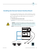
Installing the External Contact Interface Board
26 Agilent 1200 Series Getting Connected Guide Thermo Scientific
2. Unplug the power cable that connects the device to line power.
3. To prevent damage to the contact closure board, make sure that you are using ESD
protection. For more information on preventing damage caused by an electric discharge,
refer to the manual that came with the Agilent device.
4. To remove the cover plate from the slot where you plan to install the external contact
interface board, loosen the two screws that fasten the plate to the chassis of the module.
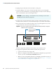
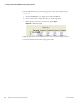
5. Insert the external contact interface board into the slot, and then tighten the two screws
to fasten the board to the chassis of the module (Figure 19).
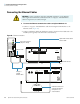
Figure 19. View of the external contact interface board (BCD board) installed in an Agilent
1200 Series pump or autosampler
You have completed the installation of the external contact interface board.
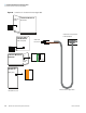
6. To trigger data acquisition from the Thermo Scientific mass spectrometer:
a. Connect the external contact trigger cable.
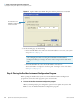
b. When you configure this device from the Instrument Configuration program, make
sure that you select the Contact board installed check box.
c. When you create an instrument method for your LC/MS system, make sure that you
create an appropriate time program for the trigger signal (see Chapter 6, “Setting Up
the Instrument Method to Trigger Data Acquisition.” )
CAUTION To prevent damage to an instrument, always use ESD protection when
handling electronic boards and components.
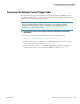
1 8
CAN CAN HP-1B CONFIG
RELAY CONTACTS
REMOTE RS232
VIAL- # -OUTPUT
Screws for fastening
the external contact
interface board