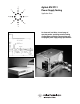
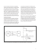
Agilent AN 372-1 Power Supply Testing Application Note An electronic load offers a broad range of operating modes, providing versatile loading configurations needed for characterizing and verifying DC power supply design specifications.
Introduction As regulated-power supply technology evolves, testing methods for design verification and product function require more sophisticated electronic equipment. The different power supply architectures and output combinations also dictate the need for versatile test instruments that can accommodate a broad range of specifications. As a result, one testing requirement that has been growing in importance is the method of loading the power supply under test.
An Overview of Power Supply Testing Needs Power supplies are used in a wide variety of products and test systems. As a result, the tests performed to determine operating specifications can differ from manufacturer to manufacturer, or from end user to end user. For instance, the tests performed in an R&D environment are primarily for power supply design verification. These tests require high performance test equipment and a high degree of manual control for bench use.
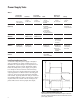
Power Supply Tests Table 2 Load Transient Recovery Time Electronic Load trise ≤15 µs Trigger output to the oscilloscope Load Effect Current Limit Characterization 1% programming accuracy CC or CR mode 1% programming accuracy CR or CC mode Efficiency and Power Factor Start-Up 1% programming accuracy CC or CR mode Low PARD 1% programming accuracy CC or CV mode 1% programming accuracy CR mode PARD Digital Oscilloscope tsample ≤100 ns N/A N/A tsample ≤25 ns DC to 20 MHz minimum bandwidth Record
For a step change in load current, a marginally stable CV power supply will have a ringing voltage output. This defeats the purpose of the power supply’s regulation circuitry and can be damaging to voltage-sensitive loads. An example of a voltagesensitive load is the logic circuitry in a computer. In this case, a computer manufacturer that purchases power supplies from an external source may consider verifying the load transient recovery specification of the power supply subassembly.
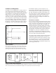
Load Effect (Load Regulation) Load Effect or Load Regulation is a static performance measurement which defines the ability of a power supply under test to remain within specified output limits for a predetermined load change (see Figure 3). In a CV power supply, the influenced quantity of interest is the steady-state output current. In a CC power supply, the influenced quantity is the steady-state output voltage.
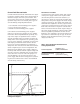
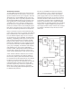
Current Limit Characterization Current limit measurements demonstrate the degree to which a constant voltage power supply limits its maximum output current to a preset value. This preset value can be fixed or variable throughout a specified range. There are basically three types of current limiting design implementations: 1. Conventional current limiting power supplies 2. CV/CC mode power supplies 3.
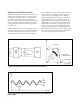
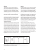
PARD (Periodic and Random Deviation) PARD (formerly known as ripple and noise) is the periodic and random deviation of the DC output voltage from its average value, over a specified bandwidth, and with all other parameters constant. It is representative of all undesirable AC and noise components that remain in the DC output voltage after the regulation and filtering circuitry (see Figure 7). PARD is measured in rms or peak-to-peak values, and is typically specified over a bandwidth range of 20 Hz to 20 MHz.
Test Overview/Procedures To make PARD measurements, the electronic load used should operate in CR mode for constant voltage and constant current power supplies. The load should also have lower PARD than the power supply being tested. This is especially important when measuring the PARD of linear power supplies, since they typically have excellent PARD specifications. A regulated AC source should be applied to the input of the power supply under test.
Efficiency Start-Up The efficiency of a power supply is simply the ratio of its total output power to its total input power. To obtain the true input power (rms voltage x in-phase rms current) of a typical AC-to-DC converting power supply, commercially available wattmeters or AC sources can be used to measure the necessary parameters. The instrument used to measure the input current and voltage must be capable of sampling the input signals at a rate fast enough to produce accurate measurements.
To fully characterize the start-up sequence of the power supply under test, measurements must be made of the output voltage response to the instantaneous application of the AC input (see Figure 11). A digital oscilloscope should be used so that storage of the output values can be accomplished for the measured start-up time period. To accurately control the AC input frequency and amplitude to the power supply under test, a regulated AC source should be used.
Other Power Supply Tests An observation of any DC power supply data sheet from a power supply manufacturer reveals a number of design specifications that must be verified and tested. These tests often differ in technique and in the test equipment that is used to measure the various parameters. The common aspect of all of these tests is that a method of controlled loading of the power supply outputs is required, which is most easily done with an electronic load.
Power Supply Testing with Agilent Electronic Loads The Agilent Electronic Load Family offers the power supply tester the solution for many of the tests that must be performed. For bench or system applications in large or small scale testing environments, Agilent Electronic Loads provide high quality and reliability with superior performance, features, and documentation. This will make power supply test system configuration easier, measurement procedures repeatable, and operating environments safer.
By internet, phone, or fax, get assistance with all your test and measurement needs. Online Assistance www.agilent.