Agilent 75000 Series C Agilent E1446A Summing Amplifier/DAC Module User’s Manual and SCPI Programming Guide Where to Find it - Online and Printed Information: System installation (hardware/software)............. VXIbus Configuration Guide* Agilent VIC (VXI installation software)* Module configuration and wiring........................ This Manual SCPI programming.............................................. This Manual SCPI example programs......................................
Table of Contents Warranty . . . . . . . . . . Safety Symbols . . . . . . WARNINGS . . . . . . . . Declaration of Conformity . . . . . . . . . . . . . . . . . . . . . . . . . . . . . . . . . . . . . . . . . . . . . . . . . . . . . . . . . . . . . . . . . . . . . . . . . . . . . . . . . . . . . . . . . . . . . . . . . . . . . . . . . . . . . . . . . . . . . . . . . . . . . . . . . 5 6 6 7 Chapter Contents . . . . . . . . . . . . . . . . . . General Description . . . . . . .
. Command Reference Chapter Contents . . . . . . . . . . . . . . . . . . Command Types . . . . . . . . . . . . . . . . . . Common Command Format . . . . . . . . . . SCPI Command Format . . . . . . . . . . . . . . Command Separator . . . . . . . . . . . . . . Abbreviated Commands . . . . . . . . . . . . Implied (Optional) Keywords . . . . . . . . . SCPI Command Parameters . . . . . . . . . . . . Parameter Types, Explanations, and Examples Querying Parameter Settings . . . . . . . . . .
INPut2 . . . . . . . . . . . . . . . . . . . . :ATTenuation . . . . . . . . . . . . . . . :IMPedance . . . . . . . . . . . . . . . . OUTPut1 . . . . . . . . . . . . . . . . . . . :ATTenuation . . . . . . . . . . . . . . . :IMPedance . . . . . . . . . . . . . . . . :OVERload? . . . . . . . . . . . . . . . [:STATe] . . . . . . . . . . . . . . . . . [:STATe]:ACTual? . . . . . . . . . . . . OUTPut2 . . . . . . . . . . . . . . . . . . . :IMPedance . . . . . . . . . . . . . . . . OUTPut3 . . . . . . . . . . . . .
A. Specifications Appendix Contents . . . . . . Inputs . . . . . . . . . . . . Outputs . . . . . . . . . . . Gain Characteristics . . . . Offset . . . . . . . . . . . . AC Characteristics . . . . . General VXI Characteristics . . . . . . . . . . . . . . . . . . . . . . . . . . . . . . . . . . . . . . . . . . . . . . . . . . . . . . . . . . . . . . . . . . . . . . . . . . . . . . . . . . . . . . . . . . . . . . . . . . . . . . . . . . . . . . . . . . . . . . . . . . . . . . . . . . . . .
Certification Agilent Technologies certifies that this product met its published specifications at the time of shipment from the factory. Agilent Technologies further certifies that its calibration measurements are traceable to the United States National Institute of Standards and Technology (formerly National Bureau of Standards), to the extent allowed by that organization’s calibration facility, and to the calibration facilities of other International Standards Organization members.
Printing History The Printing History shown below lists all Editions and Updates of this manual and the printing date(s). The first printing of the manual is Edition 1. The Edition number increments by 1 whenever the manual is revised. Updates, which are issued between Editions, contain replacement pages to correct the current Edition of the manual. Updates are numbered sequentially starting with Update 1. When a new Edition is created, it contains all the Update information for the previous Edition.
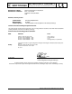
DECLARATION OF CONFORMITY According to ISO/IEC Guide 22 and CEN/CENELEC EN 45014 Manufacturer’s Name: Manufacturer’s Address: Agilent Technologies, Incorporated th 815 – 14 St. SW Loveland, Colorado 80537 USA Declares, that the product Product Name: Model Number: Product Options: Summing Amplifier/DAC E1446A This declaration covers all options of the above product(s).
Notes 8 Agilent E1446A Summing Amplifier/DAC User’s Manual
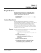
Chapter 1 Getting Started Chapter Contents This chapter provides a description of the Agilent E1446A Summing Amplifier/DAC module and describes how to install, configure, and program it. The main sections of this chapter are: • General Description . . . . . . . . . . . . . . . . . . . . . . . . . . . . . . . 1-1 • Preparation for Use . . . . . . . . . . . . . . . . . . . . . . . . . . . . . . 1-3 • Basic Operation . . . . . . . . . . . . . . . . . . . . . . . . . . . . . . . . . .
Device Information Device type: register-based C-size (1 slot) Addressing modes: A16 VXIbus Revision Compliance: 1.3 SCPI Revision: 1991.0 See side of module for power/cooling requirements Figure 1-1. The E1446A Summing Amplifier/DAC.
Preparation for Use This section shows you how to configure the module, install it in the Agilent 75000 Series C mainframe, address the module, and download the SCPI driver. Note Configuring the Amplifier Logical Address The following VXIbus configuration information pertains to the Agilent E1446A Summing Amplifier/DAC. For more (VXIbus) system configuration information, refer to the C-Size VXIbus Systems "Installation and Getting Started Guide" (Agilent P/N E1405-90021).
(Agilent E1446A) logical address or the (Agilent E1445A/E1405/06) servant area must be set such that the Agilent E1446A is in the servant area of its intended commander. Figure 1-2. Setting the E1446A Logical Address. Installing the Amplifier 1-4 Getting Started The Agilent E1446A Amplifier/DAC can be installed in any mainframe slot, except slot 0. If the Agilent E1445A AFG is a part of your system, it is recommended that the Amplifier/DAC be installed in a slot adjacent to the AFG.
Figure 1-3. Installing the E1446A Summing Amplifier/DAC. Addressing the Amplifier The Agilent E1446A Summing Amplifier/DAC can be addressed by an external controller or by an embedded controller. This section describes how to address the amplifier using an external controller with the Agilent E1445A AFG, with the Agilent E1405/06 Command Module, and with an embedded controller.
Secondary GPIB Address : Determined by dividing the logical address of the device by 8. If the amplifier is used with the Agilent E1445A, the secondary address is the E1445A logical address/8. If the amplifier is used with the Agilent E1405/06 Command Module, the secondary address is the E1446A logical address/8.
Using an Embedded Controller The Agilent E1446A Summing Amplifier/DAC can be programmed across the VXIbus backplane (select code 16) from an embedded controller, such as the Agilent E1480A V/360. With this configuration, communication with the register-based amplifier module can be accomplished via four paths: 1. Embedded controller across the VXIbus backplane to the Agilent E1445A AFG (SCPI programming only). 2.
IBASIC, or BASIC/UX. Downloadable driver capability is available on the Agilent E1406 and on the E1405 with firmware revision A.06.00 or later. To verify the firmware revision of the Command Module, you can use the *IDN? Command: 10 20 30 40 50 DIM A$[40] OUTPUT 70900;"*IDN?" ENTER 70900;A$ PRINT A$ END *IDN? returns identification information for the Agilent E1405 Command Module. The result of this command is: HEWLETT-PACKARD,E1405B,0,A.06.
Figure 1-4. E1446A Summing Amplifier/DAC Block Diagram. Amplifier Block Diagram Input Output Figure 1-4 shows a block diagram of the Agilent E1446A Summing Amplifier/DAC. The Agilent E1446A Summing Amplifier/DAC has two input channels that have identical input amplifiers with independently controlled input impedance and input attenuation. The input amplifier attenuators provide independent level control prior to the summing node. The attenuation can range from 0 to 31 dB in 1 dB steps.
to 50Ω or 75Ω, or to 0Ω for driving into high impedance. The output voltage can be attenuated by either 0 or 20 dB when 50Ω or 75Ω output impedance is selected. Output attenuation is unavailable with the 0Ω mode (high impedance). The main output terminal may be enabled or disabled under user control. When disabled, the output appears as an open circuit. This output is also overload protected via an output relay.
Offset DAC Basic Operation A precision (DAC) allows the Agilent E1446A to provide DC offset voltage levels. The DAC input is a complementary offset binary code. The full scale output provides approximately ±10V into 50Ω or 75Ω load, or approximately ±20V into high impedance.
1-12 Getting Started Basic Operation
Chapter 2 Programming the Agilent E1446A Chapter Contents This chapter shows you how to program the Agilent E1446A using SCPI Commands. The programming examples found in the chapter are written in BASIC. The main sections of the chapter are: • • • • • • • • Instrument and Programming Languages . . . . . . . . . . . . Introductory Programs . . . . . . . . . . . . . . . . . . . . . . . . . . . . . Example Programs . . . . . . . . . . . . . . . . . . . . . . . . . . . . . . . .
OUTPut2 :ATTenuation :IMPedance :OVERload? [:STATe] :ACTual? [query only] [query only] OUTPut2 is the root keyword of the command, :ATTenuation, :IMPedance, :OVERload?, and [:STATe] are second level keywords, and :ACTual? is the third level keyword. A colon (:) always separates a command keyword from a lower level keyword as shown below: OUTP2:STAT:ACT? A semicolon (;) is used to separate two or more commands within the same subsystem, and can also save typing.
Executing Coupled Commands The list below identifies rules to follow when executing coupled commands: • Coupled commands must be contiguous and executed in the same program statement. This done by placing the commands in the same program line, or by suppressing the end-of-line terminator until the last coupled command has been sent. To send multiple commands in a single line or in a single statement, the commands are linked (as described previously) with a semicolon (;) and a colon(:).
Instrument Driver and Example Programs Disks The E1446A instrument driver and the example programs contained in this manual are located on the following disks: • Agilent E1446A Instrument Driver and BASIC Example Programs - 3.5" 720 kbyte disk LIF Format (E1446-10031) • Agilent E1446A Instrument Driver and BASIC Example Programs - 3.5" 1.44 Mbyte disk DOS Format (E1446-10032) The example programs are SCPI programs written in BASIC.
Introductory Programs The introductory programs in this section include: • Executing the Agilent E1446A self-test. • Resetting the Agilent E1446A and clearing the Error Queue. • Querying the Agilent E1446A power-on/reset settings. The introductory program examples in this section were written with the Agilent E1405 Command Module as the commander of the Agilent E1446A Summing Amplifier/DAC.
Resetting and Clearing the Agilent E1446A The commands to reset and clear the amplifier are: *RST *CLS Resetting the amplifier sets it to its power-on configuration. Clearing status on the amplifier clears the error queue. Resetting and Clearing the Agilent E1446A 1 10 20 30 40 50 60 !Resetting and clearing the Agilent E1446A !Assign an I/O Path for the computer, command module, and the !E1446A. Send the appropriate commands and wait for completion.
LRN 1 !RE-STORE "LRN" 10 !Assign an I/O path between the computer and the amplifier. 20 ASSIGN @Amp TO 70911 30 !Call the subprogram 40 Lrn_conf(@Amp) 50 END 60 ! 70 SUB Lrn_conf(@Amp) 80 Lrn_conf: !subprogram which queries the amp reset configuration 90 DIM Lrn$[1000] 100 OUTPUT @Amp;"*LRN?" 110 ENTER @Amp;Lrn$ 120 Lrn$=Lrn$&";" 130 REPEAT 140 I=POS(Lrn$,";") 150 PRINT Lrn$[1;I-1] 160 Lrn$=Lrn$[I+1] 170 UNTIL Lrn$="" 180 SUBEND Table 2-1. E1446A Power-On/Reset Configuration (as returned by *LRN?).
Example Programs The example programs in this section include: • Generating and amplifying sine waves • Selecting the input impedance • Using the differential (small signal) outputs • Setting a DC offset voltage • Summing two signals These programs configure the amplifier according to the block diagram of Figure 2-1. The program descriptions will often refer to this figure.
Generating and Amplifying Sine Waves The examples in this section show you how to amplify a sine wave generated by the Agilent E1445A. In the first program, the E1446A is a servant of the E1445A AFG. In the second program, the E1446A amplifies the signal from the E1445A, however; the E1446A is in the servant area of the E1405 Command Module. Amplifying Sine Waves (Agilent E1445A Commander) This program uses the E1446A to amplify a 2 Vpp E1445A AFG signal to 14.15 Vpp.
4. Set the amplifier input impedance to match the AFG output load. INPut[1]:IMPedance 5. Set the amplifier input attenuation. INPut[1]:ATTenuation 6. Set the amplifier output impedance. OUTPut2:IMPedance 7. Set the amplifier output attenuation. OUTPut2:ATTenuation 8. Place the AFG in the wait-for-arm state. INITiate:IMMediate Note Resetting the amplifier sets many of the same conditions set by subsequent (amplifier) commands in the program.
90 OUTPUT @Afg;"*CLS" 100 OUTPUT @Afg;"*SRE 32" 110 OUTPUT @Afg;"*ESE 60" 120 ! 130 !Call the subprograms 140 Rst 150 Sine_wave 160 ! 170 WAIT .
550 REPEAT 560 OUTPUT @Afg;"SYST:ERR?" !read AFG error queue 570 ENTER @Afg;Code,Message$ 580 PRINT Code,Message$ 590 UNTIL Code=0 600 STOP 610 SUBEND Amplifying Sine Waves (Agilent E1405 Commander) This program uses the same commands and sequence as previously described, except for the OUTPut[1] commands shown below: 6. Set the amplifieroutput impedance. OUTPut[1]:IMPedance 7. Set the amplifier output attenuation.
150 OUTPUT @Amp;"*CLS" 160 OUTPUT @Amp;"*SRE 32" 170 OUTPUT @Amp;"*ESE 60" 180 ! 190 !Call the subprograms 200 Rst 210 Sine_wave 220 ! 230 WAIT .
610 IF BIT(B,6) THEN !AFG requested service 620 !End of statement if error occurs among coupled commands 630 OUTPUT @Afg;"" 640 OUTPUT @Afg;"ABORT" !abort output waveform 650 PRINT "E1445A errors" 660 PRINT 670 REPEAT 680 OUTPUT @Afg;"SYST:ERR?" !read AFG error queue 690 ENTER @Afg;Code,Message$ 700 PRINT Code,Message$ 710 UNTIL Code=0 720 STOP 730 END IF 740 ! 750 !Read AMP (at sec addr 11) status byte register, clear service 760 !request bit 770 B=SPOLL(@Amp) 780 IF BIT(B,6) THEN !amplifier requested serv
attenuation(dB) = 20 LOG (Vo/(Vi * 10)) where Vo is the output amplitude and Vi is the input signal amplitude (Vo and Vi units (Vpp, Vp) must be the same). Thus, attenuation(dB) = 20 LOG (6.3/10) = -4 dB Again, the (main) output of the AFG is connected to ’Input 1’ of the amplifier. The steps of this program are: 1. Reset the E1445A AFG and E1446A amplifier. *RST 2. Set the AFG frequency, function, and amplitude.
8. Place the AFG in the wait-for-arm state. INITiate:IMMediate Note Resetting the amplifier sets many of the same conditions set by subsequent (amplifier) commands in the program. These commands are included, however, to show other parts of the amplifier configuration. IN_IMP45 1 !RE-STORE"IN_IMP45" 2 !This program sets the AFG’s output impedance and output load 3 !to 75 ohms. The Agilent E1446A amplifier’s input impedance is set to 4 !75 ohms to match the AFG.
280 ! 290 !Set up amplifier 300 OUTPUT @Afg;"INP1:IMP 75" !input impedance 310 OUTPUT @Afg;"INP1:ATT 4" !input attenuation (dB) 320 OUTPUT @Afg;"OUTP2:IMP 50" !main output impedance 330 OUTPUT @Afg;"OUTP2:ATT 0" !main output attenuation (dB) 340 ! 350 OUTPUT @Afg;"INIT:IMM" !E1445A wait-for-arm state 360 SUBEND 370 ! 380 SUB Rst 390 Rst: !Subprogram which resets the E1445 and E1446 400 COM @Afg 410 OUTPUT @Afg;"*RST;*OPC?" !reset the AFG 420 ENTER @Afg;Complete 430 SUBEND 440 ! 450 SUB Errmsg 460 Errmsg: !S
In this example, the E1446A is a servant to the E1405. As such, commands sent to the amplifier (at secondary GPIB address 11) are parsed by the Command Module rather than by the E1445A. IN_IMP05 1 !RE-STORE"IN_IMP05" 2 !This program sets the AFG’s output impedance and output load 3 !to 75 ohms. The Agilent E1446A amplifier’s input impedance is set to 4 !75 ohms to match the AFG. The 1 Vpp AFG square wave is amplified 5 !to 6.3 Vpp. 6 ! 10 !Assign I/O paths between the computer and E1445A and E1405.
340 !Set up amplifier 350 OUTPUT @Amp;"INP1:IMP 75" !input impedance 360 OUTPUT @Amp;"INP1:ATT 4" !input attenuation (dB) 370 OUTPUT @Amp;"OUTP1:IMP 50" !main output impedance 380 OUTPUT @Amp;"OUTP1:ATT 0" !main output attenuation (dB) 390 ! 400 OUTPUT @Afg;"INIT:IMM" !E1445A wait-for-arm state 410 SUBEND 420 ! 430 SUB Rst 440 Rst: !Subprogram which resets the E1445 and E1446 450 COM @Afg,@Amp 460 OUTPUT @Afg;"*RST;*OPC?" !reset the AFG 470 ENTER @Afg;Complete 480 OUTPUT @Amp;"*RST;*OPC?" !reset the AMP 490
800 PRINT 810 REPEAT 820 OUTPUT @Amp;"SYST:ERR?" !read AMP error queue 830 ENTER @Amp;Code,Message$ 840 PRINT Code,Message$ 850 UNTIL Code=0 860 END IF 870 STOP 880 SUBEND Setting DC Voltage Offsets These examples show you how to use the amplifier to add a DC offset to a signal supplied by the E1445A. In the first example, the E1446A is a servant to the E1445A. In the second example, the E1446A is a servant to the E1405 Command Module.
5. Set the amplifier input attenuation. INPut[1]:ATTenuation 6. Set the amplifier main output impedance. OUTPut2:IMPedance 7. Set the amplifier main output attenuation. OUTPut2:ATTenuation 8. Set the DC offset value. SOURce2:VOLTage[:LEVel][:IMMediate]:OFFSet 9. Place the AFG in the wait-for-arm state. INITiate:IMMediate Note Resetting the amplifier sets many of the same conditions set by subsequent (amplifier) commands in the program.
60 !Set up error checking 70 ON INTR 7 CALL Errmsg 80 ENABLE INTR 7;2 90 OUTPUT @Afg;"*CLS" 100 OUTPUT @Afg;"*SRE 32" 110 OUTPUT @Afg;"*ESE 60" 120 ! 130 !Call the subprograms 140 Rst 150 Offset 160 ! 170 WAIT .1 !allow interrupt to be serviced 180 OFF INTR 7 190 END 200 ! 210 SUB Offset 220 Offset: !Subprogram which sets up the E1445A and E1446A 230 COM @Afg 240 OUTPUT @Afg;"SOUR:FREQ1:FIX 1E3;"; !frequency 250 OUTPUT @Afg;":SOUR:FUNC:SHAP SIN;"; !function 260 OUTPUT @Afg;":SOUR:VOLT:LEV:IMM:AMPL .
510 !Read AFG status byte register and clear service request bit 520 B=SPOLL(@Afg) 530 !End of statement if error occurs among coupled commands 540 OUTPUT @Afg;"" 550 OUTPUT @Afg;"ABORT" !abort output waveform 560 REPEAT 570 OUTPUT @Afg;"SYST:ERR?" !read AFG error queue 580 ENTER @Afg;Code,Message$ 590 PRINT Code,Message$ 600 UNTIL Code=0 610 STOP 620 SUBEND Setting DC Offsets (Agilent E1405 Commander) This program uses the same commands and sequence as previously described, except for the OUTPut[1] and S
40 COM @Afg,@Amp 50 ! 60 !Set up error checking 70 ON INTR 7 CALL Errmsg 80 ENABLE INTR 7;2 90 OUTPUT @Afg;"*CLS" 100 OUTPUT @Afg;"*SRE 32" 110 OUTPUT @Afg;"*ESE 60" 120 ! 130 OUTPUT @Amp;"*CLS" 140 OUTPUT @Amp;"*SRE 32" 150 OUTPUT @Amp;"*ESE 60" 160 ! 170 !Call the subprograms 180 Rst 190 Offset 200 ! 210 WAIT .
500 ENTER @Amp;Complete 510 SUBEND 520 ! 530 SUB Errmsg 540 Errmsg: !Subprogram which displays E1445/E1446 programming errors 550 COM @Afg,@Amp 560 DIM Message$[256] 570 !Read AFG (at sec addr 10) status byte register, clear service 580 !request bit 590 B=SPOLL(@Afg) 600 IF BIT(B,6) THEN !AFG requested service 610 !End of statement if error occurs among coupled commands 620 OUTPUT @Afg;"" 630 OUTPUT @Afg;"ABORT" !abort output waveform 640 PRINT "E1445A errors" 650 PRINT 660 REPEAT 670 OUTPUT @Afg;"SYST:ERR?
Using the Differential (small signal) Outputs These examples show you how to use the amplifier’s differential (small signal) outputs. Note the following when using the outputs: • the differential (small signal) outputs are designed for high-frequency and low-power source applications. • with no attenuation, the maximum input voltage (sum of Input1 and Input2) must not exceed 2 Vpp (Figure 2-1). In the first example, the E1446A is a servant to the E1445A.
6. Set the amplifier ’Diff +’ and ’Diff -’ output impedances. OUTPut3:IMPedance OUTPut4:IMPedance 7. Place the AFG in the wait-for-arm state. INITiate:IMMediate Note Resetting the amplifier sets many of the same conditions set by subsequent (amplifier) commands in the program. These commands are included, however, to show other parts of the amplifier configuration. DIFF45 1 !RE-STORE"DIFF45" 2 !This program uses the E1446A to generate a 10 mVpp signal from a 3 !0.
170 WAIT .1 !allow interrupt to be serviced 180 OFF INTR 7 190 END 200 ! 210 SUB Diffout 220 Diffout: !Subprogram which sets up the E1445A and E1446A 230 COM @Afg 240 OUTPUT @Afg;"SOUR:FREQ1:FIX 1E3;"; !frequency 250 OUTPUT @Afg;":SOUR:FUNC:SHAP SQU;"; !function 260 OUTPUT @Afg;":SOUR:VOLT:LEV:IMM:AMPL MIN;"; !amplitude (.
Using the Differential Outputs (Agilent E1405 Commander) This program uses the same commands and sequence as previously described, except for the OUTPut2 and OUTPut3 commands shown below: 6. Set the amplifier ’Diff +’ and ’Diff -’ output impedances. OUTPut2:IMPedance OUTPut3:IMPedance In this example, the E1446A is a servant to the E1405. As such, commands sent to the amplifier (at secondary GPIB address 11) are parsed by the Command Module rather than by the E1445A.
240 ! 250 SUB Diffout 260 Diffout: !Subprogram which sets up the E1445A and E1446A 270 COM @Afg,@Amp 280 OUTPUT @Afg;"SOUR:FREQ1:FIX 1E3;"; !frequency 290 OUTPUT @Afg;":SOUR:FUNC:SHAP SIN;"; !function 300 OUTPUT @Afg;":SOUR:VOLT:LEV:IMM:AMPL MIN;"; !amplitude (.
700 STOP 710 END IF 720 ! 730 !Read AMP (at sec addr 11) status byte register, clear service 740 !request bit 750 B=SPOLL(@Amp) 760 IF BIT(B,6) THEN !amplifier requested service 770 !End of statement if error occurs among coupled commands 780 OUTPUT @Amp;"" 790 PRINT "E1446A errors" 800 PRINT 810 REPEAT 820 OUTPUT @Amp;"SYST:ERR?" !read AMP error queue 830 ENTER @Amp;Code,Message$ 840 PRINT Code,Message$ 850 UNTIL Code=0 860 END IF 870 STOP 880 SUBEND Summing Two Signals This program uses the E1446A to sum
3. Set the AFG frequency, function, and amplitude. [SOURce:]FREQuency[1][:CW|:FIXed] [SOURce:]FUNCtion[:SHAPe] [SOURce:]VOLTage[:LEVel][:IMMediate][:AMPLitude] 4. Couple the AFG output load value to the output impedance value. OUTPut[1]:LOAD:AUTO OUTPut[1]:IMPedance 5. Set the amplifier input impedance to match the AFG output load. INPut[1]:IMPedance INPut2:IMPedance 6. Set the amplifier input attenuation.
20 !Assign I/O paths between the computer and E1445As. The E1445A at 30 !secondary address 10 is the commander for the E1446A.
460 !Set up the Agilent E1446A 470 OUTPUT @Afg80;"INP1:IMP 50" !input 1 impedance 480 OUTPUT @Afg80;"INP1:ATT 0" !input 1 attenuation (dB) 490 OUTPUT @Afg80;"INP2:IMP 50" !input 2 impedance 500 OUTPUT @Afg80;"INP2:ATT 0" !input 2 attenuation (dB) 510 OUTPUT @Afg80;"OUTP3:IMP 50" !Diff + output impedance 520 ! 530 OUTPUT @Afg80;"INIT:IMM" !E1445A wait-for-arm state (10) 540 OUTPUT @Afg88;"INIT:IMM" !E1445A wait-for-arm state (11) 550 SUBEND 560 ! 570 SUB Rst 580 Rst: !Subprogram which resets the E1445As and
880 890 900 910 920 930 940 950 960 970 980 990 1000 B=SPOLL(@Afg88) !End of statement if error occurs among coupled commands OUTPUT @Afg88;"" OUTPUT @Afg88;"ABORT" !abort output waveform PRINT "E1445A (secondary address 11)" PRINT REPEAT OUTPUT @Afg88;"SYST:ERR?" !read AFG error queue (sec addr 11) ENTER @Afg88;Code,Message$ PRINT Code,Message$ UNTIL Code=0 STOP SUBEND Summing Two Signals Programming the Agilent E1446A 2-35
2-36 Programming the Agilent E1446A Summing Two Signals
Chapter 3 Command Reference Chapter Contents This chapter describes the Standard Commands for Programmable Instruments (SCPI) command set and the IEEE 488.2 Common Commands for the Agilent E1446A Summing Amplifier/DAC. Included in this chapter are the following sections: • • • • • • • Command Types . . . . . . . . . . . . . . . . . . . . . . . . . . . . . . . . . . SCPI Command Format. . . . . . . . . . . . . . . . . . . . . . . . . . . . . SCPI Command Parameters. . . . . . . . . . . . . . . . . . . . .
Agilent E1446A / Agilent E1405/06 Commands DISPlay3-7 :MONitor[:STATe] . . . . . . . . . . . . . . 3-7 OUTPut3 . . . . . . . . . . . . . . . . . . . . . . . . 3-16 :IMPedance . . . . . . . . . . . . . . . . . . 3-16 INPut[1] . . . . . . . . . . . . . . . . . . . . . . . . . 3-8 :ATTenuation . . . . . . . . . . . . . . . . . 3-8 :IMPedance . . . . . . . . . . . . . . . . . . 3-8 SOURce:VOLTage . . . . . . . . . . . . . . . . 3-17 [:LEVel][:IMMediate]:OFFset . . . . . 3-17 INPut2 . . . . . . . . . . . . .
OUTPut2 :ATTenuation :IMPedance :OVERload? [:STATe] :ACTual? [query only] [query only] OUTPut2 is the root keyword of the command, :ATTenuation, :IMPedance, :OVERload?, and [:STATe] are second level keywords, and :ACTual? is the third level keyword.
SCPI Command Parameters The following information contains explanations and examples of the parameter types found in this chapter. Parameter Types, Explanations, and Examples • Numeric Accepts all commonly used decimal representations of numbers including optional signs, decimal points, and scientific notation: 123, 123E2, -123, -1.23E2, .123, 1.23E-2, 1.23000E-01. Special cases include MIN, MAX, and INFinity.
Indefinite length block: #0 Examples of sending 4 data bytes: #14 #3004 #0 Querying Parameter Settings Unless otherwise noted in the reference section, parameter settings can be queried by adding a question mark (?) to the command which set the parameter. For example: INP:IMP 50 sets the impedance of the ’Input 1’ port to 50Ω.
This means that sending one of these commands can change the value set previously by another one of these commands. Often, this results in “Settings Conflict” errors when the program executes. To prevent these errors these commands must be executed in a “Coupling Group”. Refer to Chapter 2 for information on executing coupled commands. Linking Commands Linking IEEE 488.2 Common Commands. Use a semicolon between the commands. For example: *RST;*CLS;*OPC? Linking Multiple SCPI Commands.
Agilent E1446 / E1445 Commands SCPI Command Reference
INPut[1] The INPut[1] subsystem controls the input attenuation and impedance of the Agilent E1446A’s “Input 1” BNC. SubSystem Syntax INPut[1] :ATTenuation :IMPedance :ATTenuation INPut[1]:ATTenuation controls the input attenuator of the “Input 1” BNC. Input attenuation can range from 0 to 31 dB in 1 dB steps. Parameters Parameter Name Parameter Type Range of Values Default Units impedance numeric 0 through 31.
INPut[1] :IMPedance Comments • Executable when initiated: Yes • Coupling group: none • *RST Condition: INPut1:IMPedance 50 Example Setting 75 Ω input impedance INP:IMP 75 3-8 E1446/E1445 Command Reference Set 75 Ω input impedance INPut[1] Subsystem
INPut2 The INPut2 subsystem controls the input attenuation and impedance of the Agilent E1446A’s “Input 2” BNC. Subsystem Syntax INPut2 :ATTenuation :IMPedance :ATTenuation INPut2:ATTenuation controls the input attenuator of the “Input 2” BNC. Input attenuation can range from 0 to 31 dB in 1 dB steps. Parameters Parameter Name Parameter Type Range of Values Default Units impedance numeric 0 through 31.
INPut2 :IMPedance Comments • Executable when initiated: Yes • Coupling group: none • *RST Condition: INPut2:IMPedance 50 Example Setting 75 Ω input impedance INP2:IMP 75 3-10 E1446/E1445 Command Reference Set 75 Ω input impedance INPut2 Subsystem
OUTPut2 The OUTPut2 subsystem controls the characteristics of the Agilent E1446A’s “Main Output” BNC. The subsystem sets the output attenuation, sets the output source impedance, monitors overload conditions, and enables or disables the output. Subsystem Syntax OUTPut2 :ATTenuation :IMPedance :OVERload? [:STATe] :ACTual? [query only] [query only] :ATTenuation OUTPut2:ATTenuation controls the output attenuator of the “Main Output” BNC.
OUTPut2 :IMPedance :IMPedance OUTPut2:IMPedance sets the output impedance of the “Main Output” BNC to either 0Ω, 50Ω, or 75Ω. OUTPut2:IMPedance 0 should be selected when an open-circuit or high-impedance load is connected to the output of the Agilent E1446A. The matching impedance is removed from the amplifier output. Also, the offset voltage into an open-circuit is twice that into a matched load.
OUTPut2 [:STATe] Comments • A one (1) returned in response to the query indicates an overload condition exists. A zero (0) indicates there is not an overload condition. • Coupling group: none • *RST Condition: none Example Determining if an overload condition exists OUTP2:OVER? determine if overload condition exists [:STATe] OUTPut2[:STATe] closes or opens the output relay of the “Main Output” BNC to enable or disable the analog output. When disabled, the output appears as an open circuit.
OUTPut2 [:STATe]:ACTual? Comments • A one (1) returned in response to the query indicates the ’Main Output’ BNC is enabled. A zero (0) indicates the output is disabled.
OUTPut3 The OUTPut3 subsystem controls the output impedance of the Agilent E1446A’s “Diff Output +” output. Subsystem Syntax OUTPut3 :IMPedance :IMPedance OUTPut3:IMPedance sets the output impedance “Diff Output +” BNC to either 50Ω or 75Ω. Parameters Parameter Name Parameter Type Range of Values Default Units impedance numeric 50|75| MINimum|MAXimum Ohms MINimum selects 50Ω output impedance; MAXimum selects 75Ω.
OUTPut4 The OUTPut4 subsystem controls the output impedance of the Agilent E1446A’s “Diff Output -” output. Subsystem Syntax OUTPut4 :IMPedance :IMPedance OUTPut4:IMPedance sets the output impedance “Diff Output -” BNC to either 50Ω or 75Ω. Parameters Parameter Name Parameter Type Range of Values Default Units impedance numeric 50|75| MINimum|MAXimum Ohms MINimum selects 50Ω output impedance; MAXimum selects 75Ω.
SOURce2:VOLTage The SOURce2:VOLTage subsystem controls the output offset voltage at the Agilent E1446A’s “Main Output” BNC. Subsystem Syntax SOURce2 :VOLTage [:LEVel] [:IMMediate] :OFFSet [:LEVel][:IMMediate]:OFFSet SOURce2:VOLTage[:LEVel][:IMMediate]:OFFSet sets the offset voltage at the “Main Output” BNC. Output offset level is programmed in volts. Parameters Parameter Name Parameter Type Range of Values Default Units number numeric -9.999695 to +10.
STATus The STATus subsystem controls the SCPI-defined Operation and Questionable Signal status registers. Each is comprised of a condition register, an event register, an enable mask, and negative and positive transition filters. Each status register works as follows: when a condition occurs, the appropriate bit in the condition register is set or cleared. If the the corresponding transition filter is enabled for that bit, the same bit is set in the associated event register.
STATus :OPERation|QUEStionable:ENABle Example Querying the Operation condition register STAT:OPER? Query Operation condition register :OPERation|QUEStionable:ENABle STATus:OPERation|QUEStionable:ENABle specifies which bits of the associated event register are included in its summary bit. The summary bit is the bit-for-bit logical AND of the event register and the unmasked bit(s).
STATus :OPERation|QUEStionable:NTRansition STAT:EVEN? Query Operation event register :OPERation|QUEStionable:NTRansition STATus:OPERation|QUEStionable:NTRansition sets the negative transition mask. For each bit unmasked, a 1-to-0 transition of that bit in the associated condition register will set the same bit in the associated event register.
STATus :PRESet Comments • Executable when initiated: Yes • Coupling group: none • Related commands: STATus subsystem, *SRE, *STB? • *RST Condition: unaffected • Power-on Condition: STATUS:OPERation|QUEStionable:PTRansition 32767 :PRESet STATus:PRESet initializes the enable registers and transition masks for the Operation and Questionable Signal status registers and sets STATus:OPC:INITiate ON.
SYSTem The SYSTem subsystem returns error messages and the SCPI version number to which the Agilent E1446A complies. Subsystem Syntax SYSTem :ERRor? :VERSion? [query only] [query only] :ERRor? SYSTem:ERROR? returns the error messages in the error queue. See Appendix B for a listing of possible error numbers and messages. Comments • The Agilent E1446A places any generated errors into the error queue. The queue is first-in, first out.
SYSTem :VERSion? Example Querying the SCPI revision SYST:VERS? SYSTem Subsystem Query SCPI revision E1446/E1445 Command Reference 3-23
Table 3-1. Agilent E1446A/E1445A Command Quick Reference.
Agilent E1446 / E1405/06 Commands SCPI Command Reference
DISPlay The DISPlay subsystem enables the amplifier’s settings (e.g. input impedance, input attenuation, output impedance, output attenuation, ...) to be monitored. When a display terminal is connected to the E1405 Command Module and monitor mode is enabled, the E1446A amplifier settings (and changes to the settings) are shown on the terminal. Subsystem Syntax DISPlay :MONitor [:STATe] :MONitor[:STATe] DISPlay:MONitor[:STATe] enables/disables the monitor mode.
INPut[1] The INPut[1] subsystem controls the input attenuation and impedance of the Agilent E1446A’s “Input 1” BNC. Subsystem Syntax INPut[1] :ATTenuation :IMPedance :ATTenuation INPut[1]:ATTenuation controls the input attenuator of the “Input 1” BNC. Input attenuation can range from 0 to 31 dB in 1 dB steps. Parameters Parameter Name Parameter Type Range of Values Default Units impedance numeric 0 through 31.
INPut[1] :IMPedance Comments • Coupling group: none • *RST Condition: INPut1:IMPedance 50 Example Setting 75 Ω input impedance INP:IMP 75 INPut[1] Subsystem Set 75 Ω input impedance E1446/E1405/06 Command Reference 3-9
INPut2 The INPut2 subsystem controls the input attenuation and impedance of the Agilent E1446A’s “Input 2” BNC. Subsystem Syntax INPut2 :ATTenuation :IMPedance :ATTenuation INPut2:ATTenuation controls the input attenuator of the “Input 2” BNC. Input attenuation can range from 0 to 31 dB in 1 dB steps. Parameters Parameter Name Parameter Type Range of Values Default Units impedance numeric 0 through 31.
INPut2 :IMPedance Comments • Coupling group: none • *RST Condition: INPut2:IMPedance 50 Example Setting 75 Ω input impedance INP2:IMP 75 INPut2 Subsystem Set 75 Ω input impedance E1446/E1405/06 Command Reference 3-11
OUTPut1 The OUTPut1 subsystem controls the characteristics of the Agilent E1446A’s “Main Output” BNC. The subsystem sets the output attenuation, sets the output source impedance, monitors overload conditions, and enables or disables the output. Subsystem Syntax OUTPut1 :ATTenuation :IMPedance :OVERload? [:STATe] :ACTual? [query only] [query only] :ATTenuation OUTPut1:ATTenuation controls the output attenuator of the “Main Output” BNC.
OUTPut1 :OVERload? When OUTPut1:IMPedance is set to either 50Ω or 75Ω, either no output attenuation or 20 dB may be selected. OUTPut1:ATTenuation must be set to 0dB when OUTPut1:IMPedance is set to 0Ω. Parameters Parameter Name Parameter Type Range of Values Default Units impedance numeric 0|50|75| MINimum|MAXimum Ohms MINimum selects 0Ω output impedance; MAXimum selects 75Ω.
OUTPut1 [:STATe] [:STATe] OUTPut1[:STATe] closes or opens the output relay of the “Main Output” BNC to enable or disable the analog output. When disabled, the output appears as an open circuit. Parameters Parameter Name Parameter Type Range of Values Default Units mode boolean OFF|0|ON|1 none Comments • Coupling group: none • *RST Condition: OUTPut1:STATe ON • The output relay will be opened automatically if an output current overload occurs.
OUTPut2 The OUTPut2 subsystem controls the output impedance of the Agilent E1446A’s “Diff Output +” output. Subsystem Syntax OUTPut2 :IMPedance :IMPedance OUTPut2:IMPedance sets the output impedance “Diff Output +” BNC to either 50Ω or 75Ω. Parameters Parameter Name Parameter Type Range of Values Default Units impedance numeric 50|75| MINimum|MAXimum Ohms MINimum selects 50Ω output impedance; MAXimum selects 75Ω.
OUTPut3 The OUTPut3 subsystem controls the output impedance of the Agilent E1446A’s “Diff Output -” output. Subsystem Syntax OUTPut3 :IMPedance :IMPedance OUTPut3:IMPedance sets the output impedance “Diff Output -” BNC to either 50Ω or 75Ω. Parameters Parameter Name Parameter Type Range of Values Default Units impedance numeric 50|75| MINimum|MAXimum Ohms MINimum selects 50Ω output impedance; MAXimum selects 75Ω.
SOURce:VOLTage The SOURce:VOLTage subsystem controls the output offset voltage at the Agilent E1446A “Main Output” BNC. Subsystem Syntax [SOURce] :VOLTage [:LEVel] [:IMMediate] :OFFSet [:LEVel][:IMMediate]:OFFSet SOURce:VOLTage[:LEVel][:IMMediate]:OFFSet sets the offset voltage of the “Main Output” BNC. Output offset level is programmed in volts. Parameters Parameter Name Parameter Type Range of Values Default Units number numeric -9.999695 to +10.
STATus The STATus subsystem controls the SCPI-defined Operation and Questionable Signal status registers. Each is comprised of a condition register, an event register, an enable mask, and negative and positive transition filters. Each status register works as follows: when a condition occurs, the appropriate bit in the condition register is set or cleared. If the the corresponding transition filter is enabled for that bit, the same bit is set in the associated event register.
STATus :OPERation|QUEStionable:ENABle :OPERation|QUEStionable:ENABle STATus:OPERation|QUEStionable:ENABle specifies which bits of the associated event register are included in its summary bit. The summary bit is the bit-for-bit logical AND of the event register and the unmasked bit(s).
STATus :OPERation|QUEStionable:NTRansition :OPERation|QUEStionable:NTRansition STATus:OPERation|QUEStionable:NTRansition sets the negative transition mask. For each bit unmasked, a 1-to-0 transition of that bit in the associated condition register will set the same bit in the associated event register.
STATus :PRESet • *RST Condition: unaffected • Power-on Condition: STATUS:OPERation|QUEStionable:PTRansition 32767 :PRESet STATus:PRESet initializes the enable registers and transition masks for the Operation and Questionable Signal status registers and sets STATus:OPC:INITiate ON. For both status registers, the enable registers are set to 0, the negative transition masks are set to 0, and the positive transition masks are set to 32767.
SYSTem The SYSTem subsystem returns error messages and the SCPI version number to which the Agilent E1446A complies. Subsystem Syntax SYSTem :ERRor? :VERSion? [query only] [query only] :ERRor? SYSTem:ERROR? returns the error messages in the error queue. See Appendix B for a listing of possible error numbers and messages. Comments • The Agilent E1446A places any generated errors into the error queue. The queue is first-in, first out.
SYSTem :VERSion? Example Querying the SCPI revision SYST:VERS? SYSTem Subsystem Query SCPI revision E1446/E1405/06 Command Reference 3-23
Table 3-1. Agilent E1446A/E1405/06 Command Quick Reference.
IEEE-488.
IEEE-488.2 Common Commands This section describes the IEEE-488.2 Common Commands implemented in the Agilent E1446A. The table below shows the commands listed by functional group; however, commands are listed alphabetically in the reference. Examples are shown in the reference when the command has parameters or returns a non-trivial response; otherwise, the command string is as shown in the table. For additional information, refer to IEEE Standard 488.2-1987.
*CLS *CLS *CLS clears the Standard Event Status Register, the Operation Status Register, the Questionable Signal Register, and the error queue. This clears the corresponding summary bits (3, 5, & 7) in the Status Byte Register. *CLS does not affect the enable masks of any of the status registers.
*EMC and *EMC? • *RST Condition: none; macro defintions are unaffected • Power-On Condition: no macros are defined Example Define macro to set ’Input 1’ impedance *DMC "RESTART","INP1:IMP 50" Define macro *EMC and *EMC? *EMC enables and disables macro usage. When enable is zero, macros usage is disabled. Any non-zero value enables macro usage. The query form returns 1 if macro usage is enabled, 0 if disabled. Comments • Macro definitions are not affected by this command.
*ESR? • Power-On Condition: no events are enabled Example Enable all error events *ESE 60 Enable error events *ESR? *ESR? returns the value of the Standard Event Status Register. The register is then cleared (all bits 0). Comments • Executable when initiated: Yes • Coupling group: none • *RST Condition: none • Power-On Condition: register is cleared *GMC? *GMC? returns the definition of the specified macro in IEEE-488.2 definite block format.
*IDN? Example Query macro definition *GMC? "RESTART" Query macro definition *IDN? *IDN? returns identification information for the E1446A. The response consists of four fields: HEWLETT-PACKARD,E1446A,0,A.01.00 The first two fields identify this instrument as model number E1446A manufactured by Agilent Technologies. The third field is 0 since the serial number of the E1446A is unknown to the firmware. The last field indicates the revision level of the firmware.
*LRN? *LRN? *LRN? returns a sequence of commands that may be resent to the Agilent E1446A to return it to its current programming state. Note *LRN? should be sent singly in a program message, since the number of commands in the returned sequence is large, and may vary depending on firmware revision. Comments • Executable when initiated: Yes • Coupling group: none • Related commands: *RCL, *RST, *SAV • *RST Condition: none *OPC *OPC causes the E1446A to wait for all pending commands to complete.
*PMC *PMC *PMC purges all macro definitions. Comments • Use the *RMC command to purge an single macro definition. • Executable when initiated: Yes • Coupling group: none • Related commands: *DMC, *RMC • *RST Condition: none *RCL *RCL restores a previously stored programming state from one of the 10 possible stored state areas. Number indicates which of the stored state areas should be used.
*RST • Related commands: *DMC, *PMC • *RST Condition: none *RST *RST resets the Agilent E1446A as follows: • Sets all commands to their *RST state. • Aborts all pending operations including waveform generation.
*SRE and *SRE? *SRE and *SRE? *SRE specifies which bits of the Status Byte Register are enabled to generate a service request . Event and summary bits are always set and cleared in the Status Byte Register regardless of the enable mask. Mask is the sum of the decimal weights of the bits to be enabled. The query form returns the current enable mask.
*TST? *TST? *TST? causes the E1446A to execute its internal self-test and return a value indicating the results of the test. Only communication between the command module and the on-card registers is tested. A zero (0) response indicates that the self-test passed. A one (1) response indicates that the test failed. The failure also generates an error message with additional information on why the test failed.
SCPI Conformance Information The Agilent E1446A Summing Amplifier/DAC conforms to the SCPI-1991.0 standard. The following tables list all the SCPI confirmed, approved, and non-SCPI commands that the Agilent E1446A can execute. Table 3-2. SCPI Confirmed Commands (E1446A/E1445A).
Table 3-4. Non-SCPI Commands.
Appendix A Specifications Appendix Contents This appendix contains the Agilent E1446A Summing Amplifier/DAC operating specifications. Except as noted, the specifications apply under the following conditions: • Period: 1 year • Temperature: 0° - 55° C • Relative humidity: ≤ 65% @ 0° - 40° C • Warm up time: 1 hour “Typical”, “typ”, or “nominal” values are non-warranted supplementary information provided for applications assistance.
Protection: Relay Trip. This disconnects the main output after either a voltage or a current overload of non-transient duration. The relay’s state can be queried and reset by software control. Differential Outputs These are two outputs nominally out-of-phase. Connectors: The + (in-phase) and - (antiphase) outputs have separate ground-referenced BNC connectors.
AC Characteristics Frequency Response : Full-Power Bandwidth: Small-Signal Bandwidth: General VXI Characteristics 10 MHz, all outputs 30 MHz, all outputs Size : Slots : Connectors : Weight (kg) : Device Type : VXIbus Revision Compliance : Register Level Documentation : SCPI Revision : Manufacturer Code : Model Code : C 1 P1, P2 1.4 Register, A16, D16 Servant 1.3 Yes 1991.0 4095 Decimal 419 Decimal Currents in Amps (typical) + 5v : + 12v : -12v : + 24v : -24v : -5.2v: -2v : + 5vs : I(pm) 0.36 I(dm) 0.
Appendix B Error Messages Agilent E1446A Error Messages This appendix contains a list of error messages that may be received when programming the Agilent E1446A. • Table B-1. Agilent E1446A Error Messages . . . . . . . . . . B-2 • Table B-2. Agilent E1446A Settings Conflict Errors with the Agilent E1405/06 . . . . . . . . . . . . . . . . . . . . . . . . . . B-4 • Table B-3. Agilent E1446A Settings Conflict Errors with the Agilent E1445A . . . . . . . . . . . . . . . . . . . . . . . . . . .
Table B-1. Agilent E1446A Error Messages B-2 Code Message Description -101 Invalid character -102 Syntax error Command is missing a space or comma between parameters. -103 Invalid separator Parameter is separated by a character other than a comma.
Table B-1. Agilent E1446A Error Messages (Con’t.) Code Message -178 Expression data not allowed -183 Macro execution error -221 Settings conflict See "Settings Conflict Error Messages" at the end of this table. -222 Data range error Data out of range. -270 Macro error -272 Macro execution error Macro program data sequence could not be executed due to a syntax error within the macro definition.
Table B-2. Agilent E1446A Settings Conflict Errors with the Agilent E1405/06 Command Module OUTP:ATT 20 and OUTP:IMP 0; OUTP:IMP 50 set SOUR:VOLT:OFFS < minimum; SOUR:VOLT:OFFS MIN set SOUR:VOLT:OFFS > maximum; SOUR:VOLT:OFFS MAX set Table B-3.
Appendix C Register-Based Programming Appendix Contents The Agilent E1446A Summing Amplifier/DAC (amplifier) is a register-based device which does not support the VXIbus word serial protocol. When a SCPI command is sent to the amplifier, the amplifier driver in the Agilent E1445A Arbitrary Function Generator (AFG) or in the Agilent E1405/06 Command Module parses the command and writes the information to the amplifier registers.
Figure C-1A. E1446A Amplifier Registers within A16 Address Space. Figure C-1B. E1446A Amplifier Registers within E1405 A16 Address Space.
The A16 base address used in register-based programming depends on whether the A16 address space is located inside the E1405/06 Command Module or elsewhere (e.g. embedded computer). Figures C-1A, C-1B, and Table C-1 enable you to determine the base address for the following computer configurations: • Embedded Controller (V/360) • Agilent E1405/06 Command Module Instrument BASIC (IBASIC) • External Computer over GPIB to Command Module (E1405/06) Table C-1.
Computer Configurations This section contains performance and functional information on the computer configurations that can be used with register-based programming. Throughput Speed Throughput speed is based on the amount of command parsing and whether the registers are accessed from the VXI backplane or from the GPIB. The computer configurations which allow faster throughput relative to each other are summarized below: 1.
The Register Offset and Register Number Depending on whether absolute addressing or select code 8 is used, either a register offset or register number is specified as part of the register address. Absolute addressing specifies a register offset, which is the register’s location in the block of 64 address bytes. For example, the amplifier’s DAC Control Register has an offset of 0816.
IBASIC programming using absolute addressing or select code 8 is faster than either DIAG:PEEK? and DIAG:POKE or VXI:READ? and VXI:WRITE because the registers are accessed from the VXIbus backplane rather than from the GPIB. Also, READIO and WRITEIO do not need to be repetitively parsed at runtime. Register Descriptions There are two READ and four READ/WRITE registers on the amplifier. This section contains a description and a bit map of each register.
Addressing Mode. Bits 13 and 12 indicate the addressing mode used by the device: 0 0 1 1 0 1 0 1 A16/A24 address mode A16/A32 address mode RESERVED A16 address mode The Agilent E1446 amplifier uses the A16 address mode. Manufacturer ID. Bits 11 through 0 identify the manufacturer of the device. Agilent Technologie’s ID number is 4095, which corresponds to bits 11 - 0 being set to “1".
The Status Register Address base + 0416 Reading the register at base + 0416 reads the amplifier’s Status register. The Status register monitors the amplifier’s input/output enable conditions and overload conditions. 15 14 not used MODID* (0) 13 - 12 not used (0) 11 10 9 8 Main Input 1 Input 2 Main Output Enable Enable Output Ovld State 7-0 FF16 MODID. A zero (0) in bit 14 indicates that the amplifier is selected by a high state on the P2 MODID line.
The DAC Control Register Address 15 The DAC control register sets the output level of the amplifier/DAC. 14 13 12 11 10 9 base + 0816 8 7 6 5 4 3 2 1 0 DAC Control Code DAC Control Code DAC Output Amplifier Output 000016 7FFE 16 + full scale + 1 LSB 7FFF 16 800016 0 - 1 LSB FFFF 16 - full scale - full scale: -19.9992V - 1 LSB: -.610 µV (open circuit) 0 + 1 LSB: + .610 µV (open circuit) + full scale: + 20.0000V At power-on the DAC control code is set to 0, which is - full scale.
zero (0) sets the impedance to 75Ω. Setting bit 2 to one (1) sets the impedance of the inverting output to 50Ω. Setting bit 2 to zero (0) sets the impedance to 75Ω. At power-on, the impedance of both outputs is undefined. Bit 1. Setting bit 1 to one (1) sets the ’Main’ output impedance to 0Ω. Setting bit 1 to zero (0) opens the 0Ω path. The output attenuation must be set to 0 dB (bit 7) if the impedance is set to 0Ω. Bit 5 must also be set to one (1) to get 0Ω output impedance.
Bit 0. The attenuation relays (bits 15 - 11 and bits 7 - 3) are latching relays. When energized, these relays will "latch" to an open (bit = 0) or closed (bit = 1) state and remain in that state after the energizing power is removed. Bit 0 is used to energize the latching relays. Setting bit 0 to zero (0) when setting the input attenuation energizes the relays. Setting bit 0 to one (1) after the attenuation has been set, removes the energizing source, thus, conserving power.
Programming the Amplifier Figure C-2 is a block diagram of the Agilent E1446A Summing Amplifier/DAC. The diagram shows the portions of the summing amplifier/DAC configured with register-based programming. The following information covers the sequence used to program the amplifier.
Table C-2. E1446A Register Bit Weights.
Program Sequence and Execution The recommended sequence of an E1446A register-based program is shown in Figure C-3. Previous Amplifier Configuration Set New Configuration Combined Previous / New Close relays corresponding to new configuration Relays from previous configuration and new configuration closed Configuration Remove Open relays corresponding to previous configuration Previous Configuration Figure C-3. Recommended Amplifier Configuration Sequence.
Program Execution Note Programming the Amplifier The (new) amplifier configuration is set as shown in Figure C-4. The execution sequence shown configures the amplifier from right-to-left relative to Figure C-2. Unlike other register-based devices, there is not a status bit which can be monitored to determine when the amplifier registers can be written to (WRITEIO). To allow the relays to close (or open), a 5 mS ’wait’ period (BASIC has 10 mS resolution) should be included following each WRITEIO.
A Check output relay clear main output enable bit base + 4 (bit 8) Set main output attenuation B Set Input1 attenuation Remove previous output attenuation base + C (bits 15-11 ) base + A (bits 7-6) Set Input1 impedance Open output relays (previous config) WRITEIO base + A (bits 7 - 6) base + C (bits 10-9 ) Set main output impedance base + A base + A (bit 5 ) Remove previous Input1 attenuation and impedance Set Input2 attenuation base + C (bits 7-3 ) Open main output relay if final state = open
Example Programs The program listings in this section are BASIC programs in LOAD/STORE format and are contained on the example programs disk Agilent P/N E1446-10031. GET/SAVE versions of these programs are on example programs disk Agilent P/N E1446-10032.
BASIC Subprograms The subprograms used by each register-based program are stored/saved in a separate file (file name ’E46SUBS’). These subprograms are listed after the last example (Summing Two Signals). Amplifying a Sine Wave This program uses the E1446A to amplify a 2 Vpp E1445A AFG signal to 14.15 Vpp.
240 WAIT .1 250 OFF INTR 16 260 ! 270 ! BEGIN E1446A CONFIGURATION 280 ! 290 !Declare and initialize program variables 300 ! 310 REAL In1_atten,In1_imped,In2_atten,In2_imped !input variables 320 REAL Out1_atten,Out1_imped,Out1_state !main output variables 330 REAL Out2_imped,Out3_imped !diff out variables 340 REAL Offset !DC offset variable 350 ! 360 DATA 3.,50.,0.,50. 370 READ In1_atten,In1_imped,In2_atten,In2_imped !input atten and imp 380 ! 390 DATA 0.,50.
where V o is the output amplitude and V i is the input signal amplitude (V o and V i units (Vpp, Vp) must be the same). Thus, attenuation (dB) = 20 LOG 6.
360 DATA 4.,75.,0.,50. 370 READ In1_atten,In1_imped,In2_atten,In2_imped !input atten and imp 380 ! 390 DATA 0.,50.,1 !main output attenuation, impedance, and state 400 READ Out1_atten,Out1_imped,Out1_state 410 ! 420 DATA 50.,50. !differential output impedances 430 READ Out2_imped,Out3_imped 440 ! 450 Offset= 0.
140 !Reset E1445A and clear status 150 OUTPUT @Afg;"* RST;* CLS;* OPC?" 160 ENTER @Afg;Ready 170 ! 180 OUTPUT @Afg;"SOUR:FREQ1:FIX 1E3;"; !frequency 190 OUTPUT @Afg;":SOUR:FUNC:SHAP SIN;"; !function 200 OUTPUT @Afg;":SOUR:VOLT:LEV:IMM:AMPL .4VPP;"; !amplitude 210 OUTPUT @Afg;":OUTP:LOAD:AUTO ON;"; !couple load to impedance 220 OUTPUT @Afg;":OUTP:IMP 50" !output impedance 230 ! 240 WAIT .
Using the Differential (small signal) Outputs Rather than amplify the input signal, this program attenuates the signal supplied by the E1445A to obtain an output amplitude of 10 mVpp. The output can be taken at either the ’Diff + ’ or ’Diff -’ (inverted) output.
380 ! 390 DATA 0.,50.,1 !main output attenuation, impedance, and state 400 READ Out1_atten,Out1_imped,Out1_state 410 ! 420 DATA 50.,50. !differential output impedances 430 READ Out2_imped,Out3_imped 440 ! 450 Offset= 0.
80 90 100 110 120 130 140 150 160 170 180 190 200 210 220 230 240 250 260 270 280 290 300 310 320 330 340 350 360 370 380 390 400 410 420 430 440 450 460 470 480 490 500 510 520 !E1445A error checking ON INTR 16 CALL Errmsg ENABLE INTR 16;32 OUTPUT @Afg72;"* CLS" OUTPUT @Afg72;"* SRE 32" OUTPUT @Afg72;"* ESE 60" ! OUTPUT @Afg80;"* CLS" OUTPUT @Afg80;"* SRE 32" OUTPUT @Afg80;"* ESE 60" ! !Reset and clear the E1445As OUTPUT @Afg72;"* RST;* CLS;* OPC?" ENTER @Afg72;Ready ! OUTPUT @Afg80;"* RST;* CLS;* OPC?" E
530 DATA 0.,50.,0.,50. 540 READ In1_atten,In1_imped,In2_atten,In2_imped !input atten and imp 550 ! 560 DATA 0.,50.,1 !main output attenuation, impedance, and state 570 READ Out1_atten,Out1_imped,Out1_state 580 ! 590 DATA 50.,50. !differential output impedances 600 READ Out2_imped,Out3_imped 610 ! 620 Offset= 0.
180 190 200 210 220 230 240 250 260 270 280 290 300 310 320 330 340 350 360 370 380 390 400 410 420 430 440 450 460 470 480 490 500 510 520 530 540 550 560 570 580 590 600 610 620 630 ! Look for illegal values and settings conflicts ! IF In1_atten< 0 OR In1_atten> = 31.5 THEN DISP "Invalid INP1:ATT value" STOP END IF IF In1_imped< > 50. AND In1_imped< > 75. AND In1_imped< > 1.E+ 6 THEN DISP "Invalid INP1:IMP value" STOP END IF ! IF In2_atten< 0 OR In2_atten> = 31.
640 650 660 670 680 690 700 710 720 730 740 750 760 770 780 790 800 810 820 830 840 850 860 870 880 890 900 910 920 930 940 950 960 970 980 990 1000 1010 1020 1030 1040 ! If output relay open (disabled) but should be closed, clear main ! output enable bit. ! IF Out1_state AND NOT BINAND(READIO(-16,Base_addr+ 4),256) THEN WRITEIO -16,Base_addr+ 10;BINAND(READIO(-16,Base_addr+ 10),-17) END IF ! ! Set up output and input relays.
1050 1060 1070 1080 1090 1100 1110 1120 1130 1140 1150 1160 1170 1180 1190 1200 1210 1220 1230 1240 1250 1260 1270 1280 1290 1300 1310 1320 1330 1340 1350 1360 1370 1380 1390 1400 1410 1420 1430 1440 1450 1460 1470 1480 1490 1500 SELECT Out2_imped ! Set Diff+ output impedance CASE 50. Out_ctrl= BINIOR(Out_ctrl,8) ! Close 50 Ohm relay CASE 75. Out_ctrl= BINIOR(Out_ctrl,0) ! 75 Ohm - no action END SELECT ! SELECT Out3_imped ! Set Diff- output impedance CASE 50.
1510 1520 1530 1540 1550 1560 1570 1580 1590 1600 1610 1620 1630 1640 1650 1660 1670 1680 1690 1700 1710 1720 1730 1740 1750 1760 1770 1780 1790 1800 1810 1820 1830 1840 1850 1860 1870 1880 1890 1900 1910 1920 1930 1940 1950 1960 IF Out1_state THEN ! Remove previous output relay state Out_ctrl= BINIOR(Out_ctrl,16) ! Close output relay ELSE Out_ctrl= BINAND(Out_ctrl,-17) ! Open output relay END IF ! ! Relay opens start here ! ! Do output relays first ! SELECT Out1_atten ! Remove previous output attenuation
1970 ! Set inactive state by turning off input attenuator control bits 1980 ! and disabling inverter 1990 ! 2000 WRITEIO -16,Base_addr+ 12;BINIOR(BINAND(In_ctrl,1542),1) 2010 SUBEND 2020 SUB Set_e46_offset(Offset) 2030 COM /E1446/ Base_addr,INTEGER In_ctrl,Out_imped 2040 REAL Offset_dac 2050 ! 2060 ! Look for settings conflict 2070 ! 2080 IF Out_imped= 0 THEN 2090 Offset_dac= -Offset/.0006103515625 2100 ELSE 2110 Offset_dac= -Offset/.00030517578125 2120 END IF 2130 IF Offset_dac< -32768.
Errmsg Subprogram Used with ’SUMSUBS’ Program ’RGBSUM’ loads/gets its subprograms from the file ’SUMSUBS’, rather than from the file ’E46SUBS’. The only difference between these subprogram files is the subprogram ’Errmsg’. ’Errmsg’ in the file ’SUMSUBS’ reports errors from two E1445As rather than from one. Its listing is shown below.
Index A Abbreviated Commands,3-3 Address External controllers,1-5 Interface select code,1-5 Logical,1-3 Primary GPIB,1-5 Secondary GPIB,1-6 Servant area of Agilent E1446A,1-3 Addressing register,C-1 - C-3 Using an Embedded Controller,1-5 Using an External Controller,1-7 Amplifier block diagram,1-9 Amplifying Sine Waves with Agilent E1405B as commander,2-12 with Agilent E1445A as commander,2-9 Attenuation, Input Range,1-9 Attenuation, Output Executing, Coupling Commands,2-3 Range,1-10 B Base address,C-1 Bl
generating a sine wave,C-18 Generating/amplifying Sine Waves,2-9 - 2-13 setting a DC voltage offset,C-21 Setting DC Offsets,2-20 - 2-25 Setting Input Impedance,2-14 - 2-19 setting the input impedance,C-19 summing two signals,C-24 using the differential outputs,C-23 Example programs subprograms,C-26 Example Programs, register-based,C-16 - C-32 External computer programming,C-5 F Format Common Command,3-2 SCPI Command,3-2 - 3-3 G Gain Voltage,1-9 General Description Block diagram,1-9 Device information,1-2
Preparation Addressing,1-5 Configuring,1-2 - 1-3 Installing,1-4 Logical Address,1-3 Logical Address, setting,1-3 Primary GPIB,1-5 Program execution register-based,C-15 Program sequence and execution,C-14 Programming the amplifier register-based programming,C-12 - C-15 Programs, Application Selecting Input Impedance,2-17 Programs, Example Amplifying Sine Waves,2-9 Programs, Introductory Executing Self-Test,2-5 Resetting/Clearing the status registers,2-6 Programs, register-based examples,C-16 - C-32 Q Queryi
Separator Command,3-3 Setting DC Offsets with Agilent E1445A as commander,2-20 Setting Logical Address,1-3 Standard Commands for Programmable Instruments, SCPI,3-6 Status register,C-8 Subprograms,used by example programs (register-based),C-26 System Configuration,2-4 T Throughput speed,C-4 V Voltage Gain,1-9 4 - Index