Agilent Technologies, Inc 24001 E Mission www agilent corn Liberty Lake, W A 99019 .':.+:. . . .* : e . . ' Agilent Technologies Innovating the HPWay June 8,2000 Dear Customer, As of November 1, 1999, four of Hewlett-Packard's businesses, test and measurement, semiconductor products, health care solutions, and chemical analysis became a new company, Agilent Technologies. Now, many of your Hewlett-Packard products and services are in the care of Agilent Technologies.
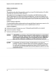
HP 8904A MULTIFUNCTION SYNTHESIZER (Including Options 001, 002, 003, and 004) Service Manual SERIAL NUMBERS This manual applies directly t o instruments with serial numbers prefixed S E W PREFIXES 2712A to 2948A and all M A J O R changes that apply to your instrument. rev.OlJUL91 For additional important information about serial numbers, refer to "INSTRUMENTSCOVERED BY THIS MANUAL" in Section 1. Fourth Edition This material may be reproduced by or for the U.S.
1 Regulatory Information (Updated March 1999) 1
Regulatory Information (Updated March 1999) Safety Considerations GENERAL This product a n d related documentation must be reviewed for familiarization with safety m a r k i n g s a n d instructions before operation. This product has been designed a n d tested in accordance with IEC Publication 1010, "Safety R e q u i r e m e n t s for Electronic Measuring Apparatus," and has been supplied in a safe condition.
Regulatory Information (Updated March 1999) Safety Considerations for this Instrument ~ WARNING This product is a Safety Class I instrument (provided with a protective earthing ground incorporated in the power cord). The mains plug shall only be inserted in a socket outlet provided with a protective earth contact. Any interruption of the protective conductor inside or outside of the product is likely to make the product dangerous. Intentional interruption is prohibited.
Regulatory Information (Updated March 1999) To prevent electrical shock, disconnect instrument from mains (line) before cleaning. Use a dry cloth or one slightly dampened with water to clean the external case parts. Do not attempt to clean internally. Ventilation Requirements: When installing the product in a cabinet, the convection into and out of the product must not be restricted.
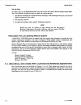
Model 8904A Contents CONTENTS Section 6 . Replaceable Parts Introduction to This Section . . . . . . . . . . . . . . . . . . . . . . . . . . . . . . . . . . . . . . . . . . . . Reference Designations and Abbreviations Used in This Manual . . . . . . . . . . . . . . . . . . . . . . . . Replaceable Parts List . . . . . . . . . . . . . . . . . . . . . . . . . . . . . . . . . . . . . . . . . . . . . . . . Ordering Parts . . . . . . . . . . . . . . . . . . . . . . . . . . . . . . . . . . . . . . . . . . . . .
Contents Model 8904A Section 8 . Service (cont’d) How to Restore the Serial Number in a Replacement A2 Digital Assembly . . . . . . . . . . . . . . . . 8-43 How to Restore Options 001 and 003 in a Replacement A2 Digital Assembly . . . . . . . . . . . . . . 8-46 How to Replace the Memory Backup Battery . . . . . . . . . . . . . . . . . . . . . . . . . . . . . . . 8-48.1 Service Sheets 1 through 4 (schematics) . . . . . . . . . . . . . . . . . . . . . . . . . . . . . . . . . . . 8-50 reu.
Replaceable Parts Model 8904A Section 6 REPLACEABLE PARTS 6-1. INTRODUCTION TO THIS SECTION This section contains information for ordering parts. Table 6- 1 lists reference designations, and Table 6-2 lists abbreviations that are used in the Replaceable Parts List. Table 6-3 lists all replaceable parts in the instrument. Table 6-4 contains the names and addresses that correspond to the manufacturer’s code numbers listed in Table 6-3.
Model 8904A Replaceable Parts How to Order To order a part in the Replaceable Parts List, call or write the nearest Hewlett-Packard Sales Office. Have the following information ready to speed the ordering process: 1. T h e Hewlett-Packard part number with the check digit. (The check digit will ensure accurate and timely processing of your order.) 2. T h e quantity required. 3. An approved purchase order number. (Sometimes required.
Model 8904A Replaceable Parts nable 6-1. Reference Designations REFERENCE DESIGNATIONS AT A . . . . . . . . assembly . . . . . . attenuator; isolator; termination B . . . . . . . . . . . . . . . fan: motor BT . . . . . . . . . . . . . . . . . battery c . . . . . . . . . . . . . . . . capacitor CP . . . . . . . . . . . . . . . . coupler CR . . . . . . . . . . . . diode; diode thyristor: varactor DC . . . . . . . directional coupler DL . ,. . . . . . . . . . . . . . delay line DS ...........
Model 8904A Replaceable Parts Table 6-2. Abbreviations (2 of 2) MOD .... modulator . . . . . . . . . . . momentary MOM device) mV ................ millivolt mVac . . . . . . . . . . . millivolt, ac mVpp . . . . . . . millivolt, peakto-peak mVrms ......... millivolt, rms mW . . . . . . . . . . . . . . .milliwan MUX . . . . . . . . . . . . . multiplex MY . . . . . . . . . . . . . . . . . mylar & . . . . . . . . . . . . microampere pF . . . . . . . . . . . . . . microfarad pH . . . . . . . . . . . . .
ReplaceabIe Parts Model 8904A Table 63'.Replaceable Parts Reference HPPart Number Designation C D llfrCode Mtr. Part Number 28480 08804-60201 DIGITAL ASSEMBLY (NW DIGITAL ASSEMBLY (RESTORED) 28480 28480 08904-60102 089066Q102 1 DIGITAL ASSEMBLY (NEW) DIGITAL ASSEMBLY (RESTORED) 28480 28480 08904-60202 08904-69202 Qty.
Model 8904A Replaceable Parts fible 6-3. Replaceable Parts Reference Designation HPPart Number C 08904-60103 08904-69103 5 3 1 1 OUTPUT ASSEMBLY (NEW) OUTPUT ASSEMBLY (RESTORED) 28480 28480 08904-60103 08904-69103 0890440203 08904-69203 6 4 1 1 OUTPUT ASSEMBLY (NEW) OUTPUT ASSEMBLY (RESTORED) 28480 28480 08904-60203 08904-69203 01804116 0160-4832 0160-4832 0160-4832 1 4 4 4 11 35 NOT ASSIGNED CAPACITOR-FXD 6.8UF+-10% 35VDC TA CAPACITOR-FXD .OlUF +-1O% lWVDC CER CAPACITOR-FXD .
Replaceable Parts Model 8904A Table 6-3. Replaceable Parts Reference Designation HP Part Number C D A3C83-89 A3C90 A3C93 A3c94-200 01604835 01604B35 7 7 A3C201 A3c202 Ax203 Ax204 A3C205 A3C206 Description Mfr* Code Mfr. Part Number NOT ASSIGNED CAPACITOR-FXD .1UF +-lo% 50VDC CER CAPACITOR-FXD .1UF +-1O% 5OVDC CER NOT ASSIGNED 28480 28480 0160-4835 0160-4835 01604832 01604835 0160-4832 0160-4832 01604832 0160-4832 CAPACITOR-FXD .OlUF +-lo% lWVDC CER CAPACITOR-FXD .
Replaceable Parts Model 8904A Table 6-3.
Replaceable Parts Model 8904A % M e 6-3.
Replaceable Parts Model 8904A Table 6-3.Replaceable Parts Reference Designation HP Part Number C D A3CR429 A3CR430 19010050 1901-0050 3 3 A31 A32 A33 12518601 7 1 1251-4670 12580141 1250-0835 2 3 3 3 1250-0835 1250-0835 12514670 12580141 1 1 2 A34 A35 A36 A37 2712A to 2942A J8 2948A and abom A3J8 8 1 Description QW 8 Mfr* Code Mfr.
Replaceable Parts Model 8904A Table 63. Replaceable Parts Reference Designation HP Part Number C D QW. MMP8 A3MP7 A3MP8 03404834 03404834 03404834 A301 -13 A3014 A3015 18544477 18530281 1 1 1854-0809 18530405 2 A301BA A3Q17A A3018A m19A A 3 m 18530659 1854-1177 i854-iin 16534659 185SC405 A3Q2lA A3oi232 A3033A A3a34-200 1854-1177 A3Q2 1 8 12 Mfr. Code Mtr.
Model 8904A Replaceable Parts Table 6-3.
Model 8904A Replaceable Parts !Cable 6-3.Replaceable Parts Reference Designation HP Part Number C D A3R114 A3R115- 121 A3R122 A3R123 A3R124 0699-2233 6 0698-7276 0698-7252 5 7 A3R125 A3R126 A3R127- 135 A3R136 A3R139 A3R140 A3R141 A3R142 A3R 143 A3R201 0698-7266 0757-0417 Description 1 1 1 0698-7229 0698-7229 RESISTOR 50.4 .lo, .5W TF TC=O+-25 NOT ASSIGNED RESISTOR 46.4K 1% .05W F TC=0+-100 RESISTOR 4.64K 1% .05W F TC=0+-100 NOT ASSIGNED RESISTOR 17.8K 1% .
~ ~ Replaceable Parts Model 8904A Table 6-3. Replaceable Parts Reference Designation A3R231 A3R232 A3R233 A3R234-299 A3R300 HP Part Number C D atv.
Replaceable Parts Model 8904A Table 6-3. Replaceable Parts Reference Designation HP Part Number A3R458 A3R459 A3R460 A3R461 06984348 069awo 069awo 0699-1726 A3R462-465 A3R466 A3R467 A3R466 A3R469 0757-0379 0757-0379 0757-0379 0757-0379 C D Mfr. Code Description Mfr. Part Number RESISTOR 3K .lob.125W F TC=O+-25 RESISTOR 21.5 1%.125W F TC=0+-100 RESISTOR 21.5 1% .125W F TC=0+-100 RESISTOR 1.150K .1% .
Replaceable Parts Model 8904A Table 6-3. Replaceable Parts Reference Designation A3U6 A3U7 A3U8 A3U9 A3U 10 A3U11- 15 A3U16 A3U17-200 A3U201 A3U202 A3U203 A3U204-400 A3U401 A3U402 A3U403 A3U404 A3U405 A3U408 -407 A3VR1-18 A3VR19 A3VR20-30 A3VR31 A3VR32 200 - HP Part Number C D 1826-1013 0 1 1858-0047 1826-1049 18550047 5 2 5 2 1 1810-0556 1 Description Mfr.
Model 8904A Replaceable Parts n b l e 6-3. Replaceable Parts Reference Designation HPPart Number C D Description 08904-61001 4 1 POWERSUPPLYASSEMBLY 28480 08904-61001 1-1197 8 1 LCDASSEMBLY 28480 1990-1197 TRANSFORMERBOARD 28480 08904-60104 Mfr. Code Mfr.
Model 8904A Replaceable Parts n b l e 6-3. Replaceable Parts Reference Designation HPPart Number C D w’ A7-A9 Description MfrCode Mfr. Part Number NOT ASSIGNED A10 Note: The A10 and A3 Assemblies are identical. Refer to A3 for individual component part numbers. tRefer t o Section 7 for update information 6-18 *Factory Selected Component (Refer t o Section 5) A Errata part change. reu.
Model 8904A Reference Designati on Replaceable Parts HPPart Number %ble 6-3.Replaceable Parts C D atv. Description Mfr. Code Mfr. Part Number Miscellaneous Parts B1 08904-61010 5 1 FANASSY 12VDC 28480 08904-61010 F1 21104003 0 1 FUSE 3A 250V NTD 1.25X.
Model 8904A Replaceable Parts %ble 6-3.
Replaceable Parts Model 8904A Table 63.Replaceable .Parts Reference Designation '". Code Mfr. Part Number Ru\R PANEL SILKSCREEN LABEL 28480 080c440010 1 DECK ASSY 28480 08004-61012 1 1 DECK ASSY 28480 08904-61016 0361-1020 0361-1020 0361-1020 2 2 2 4 RNFTSUND PLSTEM DOME-HD .125DIA RIVET-BUND PL-STEM DOME-HD .125DIA RIVET-BUND PLSTEM DOMEHD .125DIA 00201 90201 00201 A w m m2AH 6 7 8 9 10 0361-1020 1252-2245 1252-2245 21904007 21000007 2 5 5 2 2 RNEF-BUND PLSTEM DOMEHD .
Replaceable Parts Model 8904A a b l e 6-3. Replaceable Parts Reference Designation HP Part Number C D w. Description Mfr- Code Mfr.
Model 8904A Replaceable Parts Table 63. Replaceable Parts Reference Designation HPPart Number C D 69604132 1 69 29504035 8 59 29500035 8 60 0590-1251 8 60 29500035 8 61 50014539 e 2 8 4 66 57'5 68A 62 Mfr. Code Mfr.
Replaceable Parts Reference Designation Model 8904A Table 6-3.
Replaceable Parts Model 8904A Table 6-3.
Model 8904A Replaceable Parts lbble 6-3. Replaceable Parts Reference Designation HPPart Number E 2712A to 291 7A I40 141 2923A and above I40 I41 2912A to 291 7A 142-145 2923A and aboue 142 143A 144A 145 2912A to 2942A 146-148 2948A and above 146 147 148 149 2912A to 2942A 150-166 2948A and above 150 151 Mfr. Part Number NOT SEPARATELY REPLACEABLE NOT SEPARATELY REPLACEABLE NOT ASSIGNED 0890600022 05152028 05150954 0515-1234 1 6 6 7 1 2 2 9 LINE SWITCH BRACKET SCREW-MACH M2.5 X 0.
I'ZZ-9 68AON 1O'naJ
Replaceable Parts Model 8904A .' L Figure 6-1. Main Deck Assembly 6-22.4 - Top, (2923A and above) rev.
Model 8904A Replaceable Parts Figure 6-1. Main Deck Assembly - Top, Option 005 (2948A and above) rev.
Replaceable Parts Model 8904A Figure 6-2. Main Deck Assembly 6-24 - Bottom reu.
Model 8904A Replaceable Parts Figure 6-2. Main Deck Assembly - Bottom, Option 006 (2948A and above) rev.30NOV89 6-24.
Model 8904A Replaceable Parts /; 0 W W W wl Figure 6-3. Front Panel Assembly, (2712A to 291 7A), See Section 7 for Front Panel Retrofit Kit. 6-24.2 reu.
Replaceable Parts Model 8904A Figure 6-3. Front Panel Assembly, (2923A and above) reu.30NOV89 6-24.
Model 8904A Replaceable Parts Figure 6-3. Rent Panel Assembly, Option 006 (2948A and above) reu.
Replaceable Parts Model 8904A Figure 6-4. Rear Panel Assembly 6-26 rev.
Model 8904A Replaceable Parts Figure 6-4. Rear Panel Assembly, Option 005 (2948A and above) rev.30N0 V89 6-26.
Replaceable Parts Model 8904A Figure 6-5. Covers, Labels, and ROMs rev.
Replaceable Parts Model 8904A Figure 6-6. Output Cables (1 of 2) 6-28 reu.
Model 8904A Replaceable Parts Q Figure 6-6. Output Cables, Option 005 (29484 and above) (2 of 2) rev.
HP8904A Table of Contents TABLE OF CONTENTS Section 7 Instrument Changes Introduction to This Section . . . . . . . . . . . . . . . . . . . . . . . . . . . . . . . . . . . . . . . . . . . . Option Conversions . . . . . . . . . . . . . . . . . . . . . . . . . . . . . . . . . . . . . . . . . . . . . . . . . Instrument Modifications . . . . . . . . . . . . . . . . . . . . . . . . . . . . . . . . . . . . . . . . . . . . . . Front-To-Rear-Panel Output Conversion . . . . . . . . . . . . . . . . . . . . . . . .
Model 8904A Instrument Changes Section 7 INSTRUMENT CHANGES 7-1. INTRODUCTION TO THIS SECTION This section contains instrument modification recommendations and procedures that could improve the performance and reliability of your instrument. Refer to Instruments Covered by This Manual in section 1 of the H P 8904A Operation and Calibration Manual for important information about serial number coverage. 7-2.
Instrument Changes Model 8904A To retrofit Option 006 (balance output), order H P 11837A from your local Hewlett-Packard Sales office. Only instruments with serial prefix 2948A and above can be retrofit with this option. The added balanced output will replace one of the outputs already in the instrument if it has Option 002 (second internal synthesizer and output).
Model 8904A Instrument Changes 7-4. FRONT-TO-REAR-PANEL OUTPUT CONVERSION Description This procedure describes how to convert an instrument with front-panel output connectors (that is, a standard instrument) to one with rear-panel connectors (that is, Option 004). The procedure applies to instruments with one pair of outputs or two (that is, Option 002). The modifications requires partial disassembly of the instrument (removing covers and routing of cables). No soldering is required.
Instrument Changes Model 8904A Cable Routing 1. Refer to figures 7-1, 7-2 and 7-3. Remove the BNC connector ends from the front panel one at a time and insert them into the corresponding openings in the rear panel. 2. After all of the connectors have been transferred to the rear panel, secure the cables to the side rail as shown in figure 7-3 using the new cable ties. 3. Install one new lock washer and one new nut on each connector. 4.
Model 8904A Instrument Changes 7-5. REAR-TO-FRONT-PANEL OUTPUT CONVERSION Description This procedure describes how to convert a n instrument with rear-panel output connectors (that is, Option 004) to one with front-panel connectors (that is, a standard instrument). The procedure applies to instruments with one pair of outputs or two (that is, Option 002). The modifications requires partial disassembly bf the instrument (removing covers and routing of cables). No soldering is required.
Instrument Changes Model 8904A Cable Routing 1. Refer to figures 7-1, 7-2 and 7-3. Remove the BNC connector ends from the rear panel one a t a time and insert them into the corresponding openings in the front panel. 2. After all of the connectors have been transferred to the front panel, loop the cables and secure them to the front of the deck using the new cable ties as shown in figure 7-3. 3. Install one nut on each connector. 4. Tighten the nuts on the BNC connectors hand tight using the nut driver.
Instrument Changes Model 8904A Figure 7 - 1 . R o n t Panel Output Hardware \ h Figure 7-2. Rear Panel Output Hardware rev.
Instrument Changes Model 8904A w5 Figure 7-3. Output Cable Routing (ALL Options) 7 -8 rev.
Model 89048 Instrument Changes 7-6. FIRMWARE UPDATES (A2U12 AND A2U13) The -ware is changed whenever anomalies are found in the instrument’s operation which can be corrected by altering the Controller’s program. Firmware is also changed to add new features, which may only be changes in the program, or which may also result from instrument hardware changes. Replacing the ROMs Use the following procedure to install new ROMs: The ROMs ( M U 1 2 and MU131 are static sensitive devices.
Model 8904A Instrument Changes 7-7. MODIFICATION FOR POSSIBLE GROUND WIRE SHOCK HAZARD (Serial Prefix 2737A and below) O n some instruments with serial prefix 2737A and below, the grounding wire from the rear-panel line socket to the metal chassis may not have been wrapped and soldered in compliance with strict safety standards. This condition does not create a safety hazard under normal use; however, a safety hazard can develop if the following two conditions occur.
Model 8904A Instrument Changes Checking for the Shock Hazard 1. Unplug the power cord from its rear-panel socket. 2. Remove the instrument’s top cover by backing out the screw in the center of the rear edge of the cover. This is a captive screw and will cause the cover to push away from the frame. 3. Refer to figure 7-4. Locate the ground wire. It has green insulation with a yellow stripe and is inside the rear panel in the right rear corner of the instrument beneath the red and silver warning label.
Instrument Changes Model 8904A GOOD WRAPPING Wire is mechanically secure prior to soldering. The wire wrap is at least three quarters to one full turn. POOR WRAPPING (1) Wire is not mechanically secure prior to soldering. (2) Wrap is less than three quarters turn. (3) Wrap exceeds one full turn. ~~ ~ ~~ ________~ Figure 7-5. Ground Wire Wrapping Replacing the Ground Wire 1. If the wrap on either end of the ground wire is not within specification, the ground wire must be replaced. 2.
Model 8904A Instrument Changes NOTE It is possible that the 22 gauge black wire may break while replacing the new ground wire. If it does, strip 8 mm (5116 inch) of insulation from it and properly wrap and solder it to a second new lug. 10. Replace the screw in the standoff, inserting the screw through the lug with the black wire first and then through the lug with the new ground wire. Tighten the screw. 11.
Instrument Changes Model 8904A 7-9. MODIFICATION FOR POTENTIAL POWER SUPPLY SHORT (Serial Prefix 2817A and below) A problem has been noted in H P 8904A Multifunction Synthesizers with Option 002 (a second output) and with serial prefix 2817A and below. In these instruments it is possible for the heatsinks on the output transistors on the A10 Output Assembly (installed only in Option 002) to touch the bottom cover when the instrument is jarred.
Model 8904A Instrument Changes 7-1 1. MODIFICATION FOR FRONT PANEL ASSEMBLY (Serial Prefix 2712A to 2917A) INTRODUCTION HP part number 08904-61023 contains the parts to replace the front panel in HP 8904A Multifunction Synthesizers with serial prefix 2917A or below. The front-panel keys in these instruments may have a tendency to intermittently stay down when pressed. This problem cannot usually be cured by mechanical adjustment of front-panel parts or by replacement of individual parts.
Instrument Changes Model 8904A Removing the Front Panel 3. Unplug the two connectors on the top front edge of the A2 Digital Assembly that are attached to the A5 LCD Display. (Refer to figure 6-3. The two cables are labeled as P/O A5.) 4. Remove the top trim strip (item 67 in figure 6-5) and two side strips (items 61 and 62) from the front-panel frame. 5. Remove the 10 screws (items 75 through 84 in figure 6-1, 2712A to 2917A) that secure the front-panel assembly to the front frame (item 89). 6.
Model 8904A Instrument Changes Installing the Front Panel 16. Remove any existing, unneeded hole plugs from the new front-panel assembly. 17. Install the line switch bracket supplied in the kit (HP 08904-00022, item 142 in figure 7-6, Detail A herein) on to the line switch using the two Pozidriv screws supplied in the kit (HP 0515-2028, items 143 and 144). Tighten the screws to 0.6 N.m (5 in.lb). 18.
Model 8904A Instrument Changes Figure 7-6.Dont-Panel Assembly, (2923A and above) 7-18 Firmware UpdatesIHardware Modifications reu.
HP8904A Table of Contents TABLE OF CONTENTS Section 8 Service Introduction To This Section . . . . . . . . . . . . . . . . . . . . . . . . . . . . . . . . . . . . . . . . . . . . 8-1 How The Section Is Organized . . . . . . . . . . . . . . . . . . . . . . . . . . . . . . . . . . . . . . . . . . . 8.1 Safety Considerations . . . . . . . . . . . . . . . . . . . . . . . . . . . . . . . . . . . . . . . . . . . . . . . . 81 . Service Tools, Helps, and Information . . . . . . . . . . . . . . . . . . . . . . . .
Model 8904A Service Section 8 SERVICE 8-1. INTRODUCTION TO THIS SECTION This section contains information for troubleshooting and repairing the Multifunction Synthesizer. Included are principles of operation, troubleshooting checks, and schematic diagrams for selected circuits. 8-2.
Service I Model 8904A WARNING I Proper grounding of the instrument. A n y interruption of the protective (grounding) conductor (inside or outside the instrument) or disconnection of the protective earth terminal will create a potential shock hazard that could result in personal injury. Grounding one conductor of a two conductor outlet is not sufficient. Whenever it is likely that the protection has been impaired, the instrument must be made inoperative (that is, secured against unintended operation).
Model 8904A Service 8-4. SERVICE TOOLS, HELPS, AND INFORMATION Printed Circuit Board Extractor A Printed Circuit Board Extractor (HP 08904-00012) is supplied as part of this manual. It eases removal of the A3 and A10 Output Assemblies. It hooks under the board or the metal board shield so the board can be pulled off the mounting studs. Assembly, Parts, and Cable Locations The exploded view drawings at the end of Section 6 will assist in locating circuit board assemblies, cables, and mechanical hardware.
Model 8904A Service Table 8-1. Schematic Diagram Notes (1 of 11) Board Assefnb l y Board Board Test points: s y m b o l s are n u m b e r e d for easy correlation to schematic diagrams. procedures. and c o m p o n e n t location d i a g r a m s . Connection t o circuit signifies m e a s u r i n g a i d (metal Interconnect information; Circled letter with a d j a c e n t number indicates circuit-path continuation to another service s h e e t (3. in this example).
Model 8904A Service Table 8-1. Schematic Diagram Notes (2 of 11) Values for all components are marked in units of farads, henries, and ohms unless otherwise specified. * Asterisk denotes a factory-selected value. Value shown is typical. See Section V. Tool-aided adjustment. 0 Encloses front-panel designation. Encloses rear-panel designation Circuit assembly borderline Other assembly borderline.
M o d e l 8904A Service 4 Table 8-1. Schematic Diagram Notes (3 of 11) -L ,, J. 3 ,, 2 1 , , Indicates multiple paths represented by only one line. Letters or names identify individual paths. Numbers indicate number of paths represented by the line. 2 ' I Coaxial or shielded cable. Ferrite bead. (Increases the self-inductance of the conductor passing through the bead.) Relay. Contact moves in direction of arrow when energized. Indicates a pushbutton switch with a momentary (ON) position.
Model 8904A Service llzble 8-1. Schematic Diagram Notes (4 of 11) DIGITAL SYMBOLOGY REFERENCE INFORMATION Input and Output Indicators Implied Indicator-Absence of polarity indicator (see below) implies that the active state is a relative high voltage level. Absence of negation indicator (see below) implies that the active state is a relative high voltage level at the input or output. Polarity Indicator-The Dynamic Indicator-The high voltage level. Inhibit Input-Input digital device.
Model 8904A Service Table 8 - 1 . Schematic Diagram Notes (5 of 11) DIGITAL SYMBOLOGY REFERENCE INFORMATION c Combinational Logic Symbols and Functions Summing Junction-Outputs added together at a common point. 8 AND-All inputs must be active for the output to be active. 21 OR-One or more inputs being active will cause the output to be active. zm Logic Threshold-m or more inputs being active will cause the output to be active (replace m with a number).
Service Model 8904A Table 8-1. Schematic Diagram Notes (6 of 11) DIGITAL SYMBOLOGY REFERENCE INFORMATION I n Sequential Logic Functions Monostable-Single shot multivibrator. Output becomes active when the input becomes active. Output remains active (even if the input becomes inactive) for a period of time that is characteristic of the device and/or circuit. G Oscillator-The output is a uniform repetitive signal which alternates between the high and low state values.
Model 8904A Service Table 8-1. Schematic Diagram Notes (7 of 11) DIGITAL SYMBOLOGY REFERENCE INFORMATION Sequential Logic Functions (Cont’d) REG Register-Array of unconnected flip-flops that form a simple register or latch. SREG Shift Register-Array of flip-flops that form a register with internal connections that permit shifting the contents from flip-flop to flip-flop. ROM Read Only Memory-Addressable RAM Random Access Memory-Addressable capability. memory with read-out capability only.
Model 8904A Service llable 8-1. Schematic Diagram Notes (8 of 11) DIGITAL SYMBOLOGY REFERENCE INFORMATION nActive Miscellaneous Schmitt Trigger-Input characterized by hysteresis; one threshold for positive going signals and a second threshold for negative going signals. Active State-A binary physical or logical state that corresponds to the true state of an input, an output, or a function. The opposite of the inactive state.
Model 8904A Service Table 8-1. Schematic Diagram Notes (9 of 11) NAND GATE AND GATE OR GATE WITH INVERTED INPUTS L B H L L L H H L H H NOR GATE A B OR GATE B X AND GATE WITH INVERTED INPUTS L H L H L "B a x BUFFER EXCLUSIVE-OR GATE X Wl L H INVERTER OPEN COLLECTOR OUTPUTS (TTL) .
Model 8904A Service Table 8-1. Schematic Diagram Notes (10 of 11) €3 A-L I ACTIVE LEVELS Active High Input C ACTIVE HIGH inputs and outputs are indicated by the absence of the polarity indicator symbol. ACTIVE I LEVEL I Active High Output 97 < + Active Low Input ACTIVE LOW inputs and outputs are indicated by the presence of the polarity indicator symbol ( h ) .
M o d e l 8904A Service Table 8-1. Schematic Diagram Notes (11 of 11) AND The input that controls or gates other inputs is labeled with a C or a G, followed by an identifying number. The controlled or gated input or output is labeled with the same number. In this example, 1 is controlled by G1. OR When a V input is active, the output will be in its active state. With the V input inactive, the device functions as if the V input doesn’t exist.
Model 8904A Service PRINCIPLES OF OPERATION OVERALL What the Multifunction Synthesizer Can Do The HP 8904A Multifunction Synthesizer is a general purpose function generator which can output complex signals based on combinations of six waveforms: sine sawtooth triangle square noise dc Control over these signals includes: frequency, amplitude, and phase. Signals can (with Option 001) be combined by summation and/or modulation.
Model 8904A Service CHANNEL A I 6 ‘L PHASE FREOUENCY Figure 8-1. Conceptual Block Diagram of a Standard Instrument The standard instrument has only one channel-Channel A. Channel A can output one of the six available waveforms. Four of the waveforms (sine, sawtooth, triangle, and square) are periodic and thus have a frequency and phase which can be controlled. The level of all waveforms can be controlled. (Level is controlled in both the DWSIC and the analog output circuits.
Modei 8904A Service In many ways the figure resembles an analog function generator, and it may be helpful at times to visualize DWSIC operation using this analogy. (For example, the Waveform Table is analogous to an analog shaping circuit.) However, in the DWSIC all signal lines carry signal information as binary codes. Thus, the “waveforms”shown in the following figures are not really voltage-versus-timeplots but are coded-value-versus-timeplots.
Service Model 8904A P=3 is an interesting case. The count sequence (in decimal) is 0, 3, 6, 9, 12, 15, 2, 5, 8, 11, 14, 1, 4, 7, 10, 13, 0, etc. The Latch outputs three uneven staircases that repeat every 16 clock periods. In general, if P is not 0 but is small compared to the number of possible states (16 in the current example), the Latch outputs a series of staircases (sometimes uneven) with a frequency equal to the Clock frequency x P + 16.
Model 8904A Service I -: t 0 -1 3- 4 BITS 5 BITS 6 BITS ~ ~ ~ ~ ~~ Figure 8-5. T h e Output of the Waveform Table with Data Bus Widths of 4, 5, and 6 Bits With a four-bit data bus, the poor resemblance to a sine wave is apparent. With only four-bit quantization, the resolution is very coarse. A vast improvement is made by increasing the number of quantization states by increasing the width of the data buses. Examples of 5 and 6 bit data buses are also illustrated in Figure 8-5.
Model 8904A Service ~ - * CHANNEL A t OUTPUT! LEVEL I PULSE t r_+_o 'L x 'L CHANNEL LEVEL PHASE FREOUENCY B PULSE \SUM p 1 Lt- FREOUENCY LEVEL SUM q LEVEL 9 @ CHANNEL C CHANNEL PHASE 0 /L FREOUENCY PHASE 0 'L FREOUENCY D Figure 8-6.
Model 8904A Service f=pjT SAMPLER D7E Figure 8-7. Analog Output Block Diagram Analog Waveform Processing The analog waveform processing block diagram is shown in figure 8-7. Instruments with Option 002 have a second, identical output assembly. The DAC receives digital inputs from the instrument’s controller and converts them to an analog voltage. Because the DAC output has significant switching transients, each new output is sampled after settling.
Service Model 8904A HP 8904A MULTIFUNCTION SYNTHESIZER r - - - - I A2 DIGITAL ASSY 10 MHz EXT REF IN - > L A5 DISPLAY ASSY I I 1 I HP- I B I I I I I I I I I A4 POWER SUPPLY ASSY I t DWSIC - -L A < I 10 MHz REF OUT ~-I 1 < DIGITAL PORT OUTPUTS 1 OUTPUT (OPT 0021 2 Figure 8-8. Interrelationship of Instrument Assemblies (Serial prefix 2942A and below) 8-22 Principles of Operation (Overall) rev.
Model 8904A Service IP 8 9 0 4 A MULTIFUNCTION r------ I I -p-t' SYNTHESIZER A 2 DIGITAL ASSY HP-18 10 MHz EXT REF IN 1 1 I I I I DIGITAL I (OPT 005) RE&{ OUTPUT 1-I COMPU INPUT (OPT 005) OUTPUT I A1 ER REF OUT PORT ASSY OUTPUTS Figure 8-8.1. Interrelationship of Instrument Assemblies (Serial prefix 2948A and above) rev. 15DEC89 Principles of Operation (Overall) 8-22.
Model 8904A Service A2 DIGITAL ASSEMBLY General The A2 Digital Assembly creates the output waveforms as a series of digital codes (via its DWSIC) and performs the overall control and functioning of the instrument (via its microprocessor). Specific tasks include e e e e e e e 0 e e e e e e e control the instrument’s general operation create the digital waveforms distribute waveform data to the proper output control the programmable analog circuits (attenuators, filters, etc.
Service Model 8904A A3 OUTPUT ASSEMBLY (Service Sheets 1 through 4) General The A3 Output Assembly converts the digitally encoded waveform from the digital waveform synthesis integrated circuit (DWSIC) on the A2 Digital Assembly to a precise and useable analog signal. Instruments with Option 002 have a second Output Assembly (designated A10) which is identical to A3. For troubleshooting purposes the two Output Assemblies can be interchanged or compared node-for-node.
Model 8904A Service R202 t15V 0201 4 4) - R206 b FROM CLOCK SYNC U2A (HIGH TRUE) HI c221 - 61 0205 CR206 c208 II TI - c207 I II +bV - R205 R204 +15V 0202 -- I tI d l CR203 0206 R226 -15V Figure 8-9. Simplified Diagram of the Sampler Drive Differential input transistors (Q205 and Q206) are driven in complement by the outputs of D flip-flop U2A (the Clock Sync flip-flop). The emitter current for Q205 and Q206 is supplied by a common 10 mA current source.
Service Model 8904A +15V & +15v R213 I c201 II 11 + TO LOW-PASS FILTER DAC-ANLSA’LIPLER r - 1 I;+(f\; I R216 I iz L - - - - I t T H l S LINE IS AT GUARD TRACE POTENTIAL Figure 8-10. Simplified Diagram of the Sampler Amplifier Sampler Amplifier The Sampler Amplifier must accurately track the DAC output voltage when the Sampler Switch is closed and faithfully hold the sampled voltage when the switch is open.
Model 8904A Service Low-Pass Filters (Service Sheet 2) Precise construction of the analog waveform from the DAC requires careful filtering. Since the samples from the DAC are clocked through at approximately 1.67 MHz, sampling theory dictates that a low-pass filter of approximately 840 kHz or less is required; in practice the 3 dB corner will be less than this but it must be greater than 600 kHz, which is the upper frequency limit for a sine wave.
Service Model 8904A Floating Amplifier Driver and On/Off Switch (Service Sheet 3) The On/Off Switch is opened for 15 ms when the Sharp Cutoff Filter is in and the frequency of the signal is changed to prevent the ringing in the filter from getting t o the instrument’s output. The unity-gain, inverting buffer amplifier formed by U403 and U404 isolates the Floating Output Amplifier from the Sine X/X Compensation.
Model 8904A Service TROUBLESHOOTING GENERAL The goal of the following troubleshooting procedures is to isolate the fault to a single, replaceable assembly. The instrument assemblies are as follows: 0 0 0 0 0 0 0 A1 Keyboard A2 Digital A3 Output A4 Power Supply A5 Display A6 High Power Output (Installed only in Option 006) A10 Output (Installed only in Option 002) The exploded drawings at the end of section 6 in the manual will assist in locating, disassembling, and reassembling these assemblies.
Service Model 8904A A2 DIGITAL ASSEMBLY TO A3 (OR A10) OUTPUT ASSEMBLY INTERFACE Description The following procedure will help identify whether an instrument failure is due to the analog output circuits or their control inputs. Since the layout of the instrument board assemblies breaks the circuit assemblies along digital-analog lines, this procedure will also help determine which assembly (the A2 Digital Assembly or the A3 (or A10) Output Assembly) is at fault.
Model 8904A Service Tools: No. 2 Pozidriv Screwdriver Needlenose Pliers PC Board Extractor (included with Service Manual or order: HP 08904-00013) 1. Turn instrument off, unplug power cord and remove bottom cover. 2. Disconnect ribbon cable, W17. from A1 OJ1 \ 3. Remove hold-down screw and washer from center of A10 Ouput Assembly using Pozidriv screwdriver. \ 4. Pull A10 from each of its seven mounting posts.
Model 8904A Service , 1 1 6 . 3 Vdc (to J1 P i n 2 8 ) - 1 6 . 3 Vdc (to J1 P i n 31) _________-Serial Prefix 2948A and above o n l y N o t Opt 006 ~ , ~ , , , I 'Opt 006, +5. lVdc (to J; P i n 34) I -16.3 Vdc :to ,I: I Piis 29 a n d 3 0 ) + ! t t . 5 Vdc (ts J1 P i n s 26 a n d 2 7 : Figure 8-12. Power Supply Testpoints on A3 or A10 8-32 Troubleshooting (Digital/Output Interface) rev.
Model 8904A Service 3b. Clock Checks (Using a Counter) a. If the counter has an external 10 MHz timebase reference input, connect it to the rear-panel 10 MHz REF OUT of the Multifunction Synthesizer. NOTE If the counter does not have an external reference, the readings in the following steps may be off several counts. This does not indicate a failure. b. Connect the high-impedance counter input to pin 3 of U2. The counter should read within one count of 6.71088 MHz. c.
Service Model 8904A 4b. Digital-to-Analog Converter Check (Using a Counter) a. If the counter has an external 10 MHz timebase reference input, connect it to the rear-panel 10 MHz REF OUT of the Multifunction Synthesizer. NOTE I f the counter does not have a n external reference, the readings in the following steps may be off several counts. T h i s does not indicate a failure. b. On the Multifunction Synthesizer, press SHIFT PRESET.
Model 8904A Service 5. Miscellaneous Control Checks a. On the Multifunction Synthesizer, press SHIFT PRESET. After the instrument presets, key in For A3 Output Assembly For A10 Output Assembly fl (Channel Config.) fl (Channel Config.) NEXT NEXT NEXT b. Connect a dc coupled, high-impedance oscilloscope or logic probe to the pin of the IC listed in the table below. For each connection, key in the sequences listed in the table (in the order listed) and note the logic state.
Service Model 8904A 6. Overvoltage Control Checks a. On the Multifunction Synthesizer, press SHIFT PRESET. After the instrument presets, key in For A3 Output Assembly For A10 Output Assembly SHIFT SERVICE NEXT NEXT f3 (Memory Map Access) NEXT NEXT NEXT NEXT SHIFT SERVICE NEXT NEXT f3 (Memory Map Access) NEXT NEXT NEXT NEXT NEXT 80 80 b. Connect a dc coupled, high-impedance oscilloscope or logic probe to pin 12 of U2. The voltage should be a TTL low. c. Press SHIFT. The voltage should be a TTL high.
Model 8904A Service n b l e 8-2.
Service Model 8904A A2 DIGITAL ASSEMBLY TO A1 KEYBOARD ASSEMBLY INTERFACE Description The following procedure will help identify whether a keyboard failure is due to the keyboard itself or the controller. It does this by checking signals on the interface between the two assemblies. If the tests pass but the instrument does not respond to keyboard inputs, the A2 Digital Assembly should be replaced. If the tests fail, trace the signal to the A1 Keyboard Assembly.
Model 8904A Service NOTE Ignore the beeper and the display as keys are pressed. If p i n 8 o n A2U4 is always high, a key is probably stuck down. IC on A2 Pin u3 17 fl, f2, SHIFT, 7, 2 All other keys Goes Low Always High u3 15 NEXT, LAST, LOCAL, -, 3, 9 All other keys Goes Low Always High u3 13 f3, f4, e = ,kHz V, deg pV All other keys Goes Low Always High u3 11 FREQ, PHASE, 0 , 5 ,0 All other keys Goes Low Always High u3 a 0 , AMPTD, WAVE FORM, 6,.
Service Model 8904A Key Sequence Annunciator Status IC on A2 Pin Level ( l T L ) (None) SHIFT FLOAT 1 OFF FLOAT 1 On Off U38 13 L H (None) SHIFT FLOAT 2 OFF FLOAT 2 On Off u35 13 L H (None) SHIFT OUTPUT 1 OFF ON 1 On Off u2 16 (None) SHIFT OUTPUT 2 OFF ON 2 On Off u2 17 L H L H 3. HP-IB Annunciators Check a. On the Multifunction Synthesizer, press SHIFT PRESET.
Model 8904A Service A2 DIGITAL ASSEMBLY TO A5 DISPLAY ASSEMBLY INTERFACE Description A failure in the A5 Display Assembly can cause the entire instrument to hang up at power up. If this condition is suspected, measure pin 12 of A2U25 or pin 4 of A2U20 with a high impedance, dc coupled oscilloscope. TTL pulses should be seen with 1 ps high and 15 ps low. (The signal is normally a TTL high.
Service Model 8904A A3 OR A10 OUTPUT ASSEMBLY Description The following procedure will assist in locating a fault on the A3 or A10 Output Assembly. It is wise to perform the procedure titled A2 Digital Assembly to A3 (or A10) Output Assembly Interface first to confirm that the fault is indeed on the Output Assembly. NOTE I f the instrument has Option 002, a second output, and the fault appears only o n one output, swap the A3 and A10 assemblies and see if the fault tracks the output assembly.
Model 8904A Service PHASE SYNCHRONIZATION (OPTION 005) Description The operation of the unit-to-unit phase synchronization circuits (Option 005 and serial prefix beginning 2948A only) is checked by monitoring the signals on the rear-panel clock synchronization and phase reset input and output lines. The checks should pinpoint the failure to either the A2 Digital Assembly or an interconnecting cable.
Model 8904A Service HOW TO RESTORE THE SERIAL NUMBER IN A REPLACEMENT A2 DIGITAL ASSEMBLY Description If the A2 Digital Assembly has been replaced by a new or exchange assem,,;, the instrument’s serial number suffix will need to be entered into non-volatile memory (RAM). The suffix is the last five digits of the serial number. For example, the suffix of serial number 1234A56789 is 56789. The serial suffix can be entered from the front-panel keyboard by the following procedure.
Service Model 8904A NOTE a. T h e SHIFT key is the blue key. The PRESET key is labeled in blue above the *= key. b. A f t e r 3 seconds the display will time out and read as in step 1. Press SHIFT PRESET as often as needed to view the option and serial display. C. T h e displayed option numbers are only two digits (for example, 01) even though the officialoption numbers are three digits (for example, 001). d.
Model 8904A Service 4. Key in the serial suffix which is printed on the rear-panel serial label, then press ENTER. (For example, if the serial number on the label is 1234A56789, key in 5 6 7 8 9, then press ENTER.) The display should now read: I Press SHIFT f 2 t o i n s t a l l S/N = 56789. If S/N i s wrong use f 3 Reenter f 4 Exit. I The serial suffixthat you keyed in should appear a t the end of the top line. (In the example shown it is 56789.
Service Model 8904A HOW TO RESTORE OPTIONS 001,003, AND 005 IN A REPLACEMENT A2 DIGITAL ASSEMBLY Description If the A2 Digital Assembly has been replaced by a new or exchange assembly, the instrument’s serial number suffix will need to be entered into non-volatile memory (RAM). (Restoration of the serial number is documented in the previous procedure.) After the serial number has been restored, Options 001, 003, and 005 can, where applicable, be restored.
Model 8904A Service 3. Key in SHIFT SPECIAL 4 8 ENTER SHIFT END. The display should read I **** Option Firmware I n s t a l l a t i o n **** Enter i n s t a l l a t i o n code: f4 Exit I NOTE a. The SPECIAL key is labeled in blue above the LAST key. The END key is labeled in blue above the ENTER key. b. After keying in SHIFT SPECIAL, the display should be: fl Special # 0 f2 S t a t u s = Off f4 E x i t # 0 Last s t a t e r e c a l l e d on power up c.
Model 8904A Service NOTE a. If a typing error occurs as the Codeword is being entered, the backspace (em) key can be used to back up to the digit i n error. b. If the Codeword is incorrect the display will not list the desired option and after the 10 second timeout, the display will read: * HP 8904A Main Selection Level fl Channel Config. * Begin again at step 3. 6. Switch LINE to OFF and then back to ON.
Model 890412 Service HOW TO REPLACE THE MEMORY BACKUP BATTERY Description The battery that backs up non-volatile memory has a limited lifetime. It should be replaced every five years or whenever it shows signs of deterioration. Replacing the battery must be done carefully so as to not interrupt the contents of the RAM. If the RAM looses its contents, the entire A2 Digital Assembly will have to be replaced because its serial number and option information will be lost.
Service Model 8904A 3. Partially remove the A2 Digital Assembly as follows. (figure 6-1, Main Deck Assembly-Top, be helpful.) may a. Unplug all connectors on the A2 assembly except the two soldered-in coaxial cables. (To remove the front-most keyboard ribbon cable, lift up on its retainer and push the retainer forward.) b. Remove the single Torx screw securing the A2 assembly. c.
Model 8904A Service 5. Desolder the three leads of the backup battery (A2B1) with a solder removal tool and remove the battery. 6a. If the instrument has serial prefix 2942A and below, put the three insulators (HP 3050-0990) on the leads of the new battery (A2B1, HP 1420-0281) and solder in the battery. The bottom of the battery case must not touch the circuit board or any solder pads. 6b. If the instrument has serial prefix 2948A and above, solder in the battery (A2B1, HP 1420-0338). 7.
2 c
Model 8904A Service w i m- l i n a- n - R A M U14 Capacitor cs Battery B 1 Figure 8-12.3. Component Locator for A2 Digital Assembly Detailing the Battery Backup (Serial Prefix 2948A and Above) reu.15DEC89 Troubleshooting (Memory Backup Battery) 8-48.
Service Model 8904A LINE VOLTAGES LINE 1 15VAC-25%. + 1E A F- 1 s-1 NEUTRAL 23EVAC-15%.+10% 48-6bHZ W-18 ASSEMBLY P-4 *PART OF W-12 Figure 8-12.4. Line Voltage Wiring Harness 8-48.6 Troubleshooting (Memory Backup Battery) rev.
COMP - C I 1 F i g u r e 8-13. Service Sheet Information IPI I \ I TP5 B TPB I I I TPU3 C F c2 c3 c4 c5 B,1 C6 c.1 C8 1 c,2 8.2 c10 c11 8,3 c12 c,3 C13 8,3 C14 8.3 C28 A.2 c29 A.1 C30 A,2 C31 A2 C32 A2 c33 A.2 c34 A2 c35 A.2 C36 A.2 c37 A.2 C38 A2 C40 A2 C41 A,3 C42 A.3 c43 A,3 c44 A.3 c45 A3 C46 A3 c47 A,3 C46 A.3 C50 A.3 C51 8.2 C64 B,1 C71 A.3 C72 A.3 c79 8.1 C82 8.1 c90 A3 c93 A2 c201 A.1 c202 A,1 C203 A.l C204 A.1 C205 A.1 1P.
r D I G I T A L DATA INPUT DATA LATCHES 7 c3 ' T C 8.81U DIGITAL TO ANALOG CONVERTER 7CLOCK 7 TRACK AND HOLD C I R C U I T SAMPLER DRIVE .-$.. a / SYNC,- I CR2E2 A - IPOWER SUPPLY CONDITIONERS - I 0311
Model 8904A Serv i ce A3 Component Coordinates (2 of 2) A3 Component Coordinates (1 of 2) Tpl A Flgure 8-14. Service Sheet Information t I TPI I f COMP lP2 c B I \ 1PS B IPB I I TPW Component Locator I 0 I X,V C2 D.1 c4 3 C5 C6 C8 c10 C11 c12 C13 C14 C28 C29 C30 C31 c.1 B.l C.1 8.2 c.2 B,3 c,3 B,3 8.3 A.2 A.1 A.2 A2 C33 C32 C34 C35 ?A ., A2 A.2 C36 C37 C38 C40 C41 C42 C43 C44 C45 C46 A.2 A,2 A.2 A.3 A.3 A.3 A.3 A.3 A3 C47 C48 C50 C51 A.3 A.3 8.2 C64 C71 C72 A,3 B.
Model 8904A Service CHANGES On the A3 schematic: All serial prefixes 0 rev.28MAR89 C230 - Under SHARP CUTOFF (ELLIPTIC) change the value of (2230 to - 1000pF. ss2 8-52.
zss ES-8 WAS!- I n (3)30A91- I 4 I 81 L 33(IAS* 6 ' 8 = NIV9 kl31311dWV OIanV - 31901 N3AILlO ONV SAVl3kIk dlBLL ME3 4 (3IldIll3) JJOlfl3 dWHS 'I I T 9NIkl3111J
Service A t lP1 I ? lP2 I Figure 8-15. Service Sheet Information B COMP - C c2 c3 c4 c5 C6 C8 c10 c11 c12 C13 C14 C28 c29 C30 C31 C32 c33 c34 c35 C36 c37 C38 C40 C41 C42 c43 c44 c45 C46 c47 C48 C50 C51 C64 C71 C72 c79 C82 c90 c93 c201 c202 C203 C204 C205 A3 Component Coordinates (1 of 2) X,Y D.l c.1 c.1 8.1 c.1 8.2 c.2 8.3 c.3 8.3 8.3 A,2 A,1 A.2 A.2 A,2 A,2 A,2 A,2 A,2 A,2 A.2 A,2 A,3 A,3 A,3 A,3 A.3 A,3 A,3 A,3 A.3 8.2 8.1 A3 A.3 8.1 8.1 A3 A2 A.
Model 8904A Service CHANGES On the A3 schematic: All serial prefixes 0 R417, R422 - Under FLOATING DRIVER AND ON/OFF SWITCH change the value of R417 and R422 t o 75K ohms. ss3 rev.28MAR89 8-54.
6, 12, AND 24 dB ATTENUATORS C I10 ,K TO A2 HlSCELLANEOUS CONTROL I ~~ I RlA 1K J1121) < AT1 I U10A - 1 t5VDC R1C IK +5voc *5 oc +SVDC 9 +SVOC Ul88 16 - Ul0C 2 15 AT2 I I I I+ 3 ,- 2 4 dB ATTENUATOR I ss2 COUP OUT I I1 I1 R70 7.968K I\ I K2A + I 3 13 ; 1 P I 0 K4 +5voc ' -- ' UlSF 12 5 AT3 - 6 a FOR I1 AMP D R I V E R AND ON/OFF SWITCH tSVOC --I 12 dB ATTENUATOR -1 I\ I I I I K4A I / I I I - I I MEASURE: 1.
Serv i ce + t I lP' A f A I- 0 lP2 F l g u r e 8-16. Service Sheet Information TP4 I COMP C c2 c3 c4 c5 C6 C8 c10 c11 c12 C13 C14 C28 C29 C30 C31 C32 c33 c34 c35 C36 c37 C38 C40 C41 C42 c43 c44 c45 C46 c47 C48 C50 C51 C64 C71 C72 c79 C82 c90 c93 c201 c202 C203 C204 C205 _- I El I A3 Component Coordinates (1 of 2) --x,v - I \ \ I lP5 n TPB I I I I lP4W Component Locator 1412 C TPtW I I D.l c.1 c.1 8,l c.1 82 c.2 8.3 c.3 8,3 8.3 A.2 A.l A2 A2 A.2 A.2 A.2 A.2 A,2 A.2 A.
Model 8904A Service CHANGES 2948A and above the +5VREF. Draw a jumper wire acrosse the opening and label it W1. Label the left end of the jumper, J8(2) and the right end of the jumper, J8(1).Draw node dot about 0.125 inch below J8(1)and label it, J8(3). Connect a common ground symbol to J8(3). Write the following note directly under the circuit block. “Jumper, J8, connects pins 1 and 2 for all instruments except when equipped with option 006. Connect 58 pins 2 and 3 for option 006 equipped instruments.
tSV0C + A l l I ;q 1 RELAY DRIVER L O Q l C 7 7 '5VUF \ IVERVOLTAOE 'ROTECTION ow - OVERVOLTAGE RELAY DRIVE - \- PM K11 1 -15voc I \ R15+ 1.1w P/O *ID2 FLT H l I2 1 . (7 7-ATTENUATOR 11113 b.UK - 7 4, RII4 51.40 ss3 @ 2 L I I I- OVERVOLTAGE DETECTOR +lSWC I -Rff'. t ----.---A 042b I* I 2 FLOATINO OR ORWNDED AUDIO OUTPUT 7 I LIS2 rm I II I! II OIll m I $71 I..
Model 8904A Service CHANGES ~ ~~ A6 Schematic and Component locator 2948A and above 0 0 Use the component locator on page 8-60 for the A6 High Power output assembly component locations. Use SS5 (Opt 006) on page 8-61 for the A6 High Power Oustput assembly schematic information. ss5 rev.
Service Model 8904A ss5 8-60 Figure 8-1 7.Component Locator For S55 rev.
P I 0 A3/A10 OUTPUT ASSEMBLY ------ 1I J480 ! I W18 II I 35% I I I