Operating Guide This guide describes how to use the Agilent 53150A, 53151A, and 53152A Microwave Frequency Counters. The information in this guide applies to instruments having the number prefix listed below, unless accompanied by a “Manual Updating Changes” package indicating otherwise.
Copyright Agilent Technologies, Inc. 1999, 2002 Certification and Warranty Before Cleaning Certification All Rights Reserved. Reproduction, adaptation, or translations without prior written permission is prohibited, except as allowed under the copyright laws. Agilent Technologies, Inc. certifies that this product met its published specification at the time of shipment from the factory.
Contents Contents and Organization viii Related Documents ix Types of Service Available if Instrument Fails x Repackaging for Shipment xi Description of the Microwave Frequency Counter xii Options xiii Accessories Supplied and Available xiv Agilent 53150A/151A/152A Quick Reference Guide xv 1 Getting Started The Front Panel at a Glance 1-2 The Front Panel Indicators at a Glance 1-3 The Front Panel Menus at a Glance 1-4 The Display Annunciators at a Glance 1-5 The Display Special Characters at a Glance 1-6
Contents Using Power Correction 1-26 Power Correction Theory of Operation 1-26 Increasing Profile Accuracy 1-27 Selecting a Power-Correction Profile 1-28 Entering Data Points in a Power-Correction Profile Setting the Measurement Rate 1-32 Setting the Number of Averages 1-33 Setting the Resolution 1-34 2 1-28 Operating Your Frequency Counter Introduction 2-2 Chapter Summary 2-2 How this Counter Works for You 2-3 Summary of the Measurement Sequence 2-4 Using the Selection Keys 2-5 Sequencing Through the M
Contents Measuring Relative Power 2-26 Relative Power Example 2-26 Offsetting a Power Measurement 2-27 Power Offset Example 2-27 Using Power Correction 2-30 Power Correction Theory of Operation 2-31 Increasing Profile Accuracy 2-32 Power Correction Examples 2-32 Power Correction Example: Selecting a Correction Profile Power Correction Example: Editing Data Point Values Using the Menu 2-39 Navigating in the Menu and Changing Settings 2-41 Reference Oscillator (REF OSC) 2-42 Do Self Test 2-43 Battery Voltage
Contents B Messages Overview B-2 Status Messages B-2 Self-Test Messages B-3 Error Messages B-4 C Using the Battery Option Overview C-2 Operating the Counter from the Batteries C-2 Operating the Counter from a DC Power Source Replacing the Batteries C-4 Removing the Batteries C-4 Installing Batteries C-5 Charging the Batteries C-8 Precautions C-9 vi C-3 Operating Guide
In This Guide This book is the operating guide for the Agilent 53150A (20 GHz), 53151A (26.5 GHz), and 53152A (46 GHz) Frequency Counters. It consists of a table of contents, this preface, a quick reference guide, three chapters, three appendices, and an index. This preface contains the following information: • Contents and Organization pg. viii • Related Documents pg. ix • Types of Service Available if Instrument Fails pg. x • Repackaging for Shipment pg.
In This Guide Contents and Organization The Quick Reference Guide consists of a Menu Tree (tear-out sheet) that serves as a tool to trigger your memory or get you quickly reacquainted with the instrument. Chapter 1 Getting Started is a quick-start guide that gives you a brief overview of the Counter’s keys, indicators, menus, display, and connectors. A graphical procedure for performing a measurement is also provided. Chapter 2 Operating Your Instrument is an operator’s reference.
In This Guide Related Documents For more information on frequency counters refer to the following Series 200 Application Notes: • Fundamentals of Electronic Frequency Counters, Application Note 200—Agilent part number 02-5952-7506. • Understanding Frequency Counter Specifications, Application Note 200-4—Agilent part number 02-5952-7522. • Fundamentals of Time and Frequency Standards, Application Note 52-1—Agilent part number 02-5952-7870.
In This Guide Types of Service Available if Instrument Fails If your Counter fails within one year of original purchase, Agilent will repair it free of charge. If your instrument fails after your one-year warranty expires, Agilent will repair it, or you can repair it yourself. There are three types of repair services: • Standard repair service—if downtime is not critical. • Express Repair/Performance Calibration Service—if downtime is critical.
In This Guide Repackaging for Shipment For the Express Repair/Performance Calibration Service described above, return your failed Counter to the designated Agilent Service Center, using the instrument’s original shipping carton (if available). Agilent notifies you when your failed instrument is received. If the instrument is to be shipped to Agilent for service or repair, be sure you do the following: • Attach a tag to the instrument identifying the owner and indicating the required service or repair.
In This Guide Description of the Microwave Frequency Counter The Agilent 53150A, 53151A, and 53152A Microwave Frequency Counters are capable of measuring frequencies from 10 Hz to 125 MHz on Channel 1 and from 50 MHz to 20 GHz (53150A), 26.5 GHz (53151A), and 46 GHz (53152A) on Channel 2. These frequency counters are also capable of measuring power on Channel 2 (in the same frequency ranges). All three Counters have a maximum frequency resolution of 1 Hz.
In This Guide Options The options available for the Agilent 53150A/151A/152A are listed below. Specifications for the options are listed in Chapter 3, “Specifications.” Options ordered with the Counter are installed at the factory and are ready for operation on delivery. Refer to the "Retrofitting Options" chapter in the Agilent 53150A/151A/152A Assembly-Level Service Guide for information on installing options in the field.
In This Guide Accessories Supplied and Available Accessories Supplied • Power cord, 2.
Quick Reference Agilent 53150A/151A/152A Quick Reference Guide The Quick Reference Guide is designed for experienced users of the Agilent 53150A, 53151A, and 53152A. It is intended to be used as a tool to trigger your memory. If you are using the Counter for the first time, Agilent recommends that you at least read Chapter 1, “Getting Started,” first. The Quick Reference Guide, which follows this page, consists of a menu tree that may be torn out of the guide for external use.
xvi Quick Reference
Quick Quick Reference Reference Agilent 53150A/151A/152A Frequency Counter On/Off Clear +/- Menu Reset/ Local REF OSC > INT REF OSC > EXT SAVE > 0 to 9 PRESET 53150A > RECALL > 0 to 9 OP 9999 HRS CH1 LPF > OFF BATT VOLTAGE 0.0 CH1 LPF > ON FM > AUTO FM > OFF BAUD > 9600 BAUD > 4800 BAUD > 2400 BAUD > 1200 BAUD > 19200 DO SELF TEST < 00-111-222 > < SN 999999 > Freq Offset Rate Pwr Offset Avg GPIB Resol 00 000 000 000 000 ± 00.00 GPIB± 00.
QR-2 Quick Reference
1 Getting Started
Chapter 1 Getting Started The Front Panel at a Glance The Front Panel at a Glance 1 2 3 4 20 GHz Counter 53150A GHz MHz kHz CHANNEL 1 10 Hz to 125 MHz Hz POWER 1 Ch 12 Rel Freq Offset Avg On Rel Pwr Offset Standby 1M Ω Ext Rel Hold Rate Rmt SRQ dB dBm Watts mW uW % Error Shift FREQ MODIFY Gate Freq Offset Pwr Offset GPIB Reset/ Local Rate Avg Resol Shift Clear +/- Enter Menu POWER Channel 2 CHANNEL 2 50 MHz to 20 GHz DAMAGE +27 dBm dBm/ W On/Off 20 19 18 17 16 15 14 13
Chapter 1 Getting Started The Front Panel Indicators at a Glance The Front Panel Indicators at a Glance The front panel includes three LED indicators. These are listed and described in the following table. Indicator POWER The Standby indicator is lit whenever the Main ~ Power switch on the rear panel is turned ON, and the POWER switch on the front panel is OFF (out). During Standby, most of the instrument’s circuits do not receive power.
Chapter 1 Getting Started The Front Panel Menus at a Glance The Front Panel Menus at a Glance Shift Menu Reset/ Local REF OSC > INT PRESET SAVE 53150A > 1 REF OSC > EXT > 0 to 9 RECALL > 0 to 9 OP 9999 HRS CH1 LPF > OFF BATT VOLTAGE 0.
Chapter 1 Getting Started The Display Annunciators at a Glance The Display Annunciators at a Glance GHz Ch 12 Rel Freq Offset Avg On Rel Pwr Offset MHz kHz dB dBm Watts mW uW % Hz Ext Rel Hold Rate Rmt SRQ Error Shift 1 Annunciator Description Ch 1 or Ch 2 Indicates which channel is selected to measure an input signal. Freq Indicates that the value displayed is a frequency reading. Rel Freq The displayed frequency value is relative to a previously zeroed value.
Chapter 1 Getting Started The Display Special Characters at a Glance The Display Special Characters at a Glance Special Characters Description Points to the current value for a Menu setting. 1 Indicates that the value for the current Menu setting can be changed using the selection (arrow) keys. When the letter “c” is displayed in the hundredths position of the power display, Power Correction mode is in effect.
Chapter 1 Getting Started The Rear Panel at a Glance The Rear Panel at a Glance 1 2 3 5 4 Made in U.S.A. ISM 1-A 1 with domestic and foreign content 6 OPTIONS 001 Oven Time Base 002 Battery Main ~ Power Reference 10 MHz Auxillary WARNING: In or Out To avold electric shock, do not remove covers. No user-serviceable parts inside. Refer all servicing to qualified personnel. This unit must be earth grounded.
Chapter 1 Getting Started Operating the Counter Operating the Counter The procedures in this section are designed to familiarize you with the Frequency Counter’s features and controls. Agilent suggests that you follow the steps for each of these procedures, even if you do not presently need to make any measurements or to adjust any of the Counter’s settings.
Chapter 1 Getting Started Operating the Counter The following legend defines the meanings of the icons used throughout this chapter.
Chapter 1 Getting Started Operating the Counter Turning the Counter On To turn on the Counter, turn on the Main ~ Power switch on the rear panel (see page 1-7), and then press and release the POWER button on the front panel.
Chapter 1 Getting Started Operating the Counter NOTE If a signal was applied to the Channel 2 input connector prior to turning on the Counter, CH2 NO SIGNAL is displayed momentarily. As soon as the Counter acquires the input signal, it displays the signal’s value. NOTE The internal Reference Oscillator requires 10 to 15 minutes to reach a stable operating temperature.
Chapter 1 Getting Started Operating the Counter Using the Menu The Agilent 53150A/151A/152A Counter has one menu that you use to control a number of the Counter’s features and functions. Displaying the Menu To display the Menu, press the Shift key and then the Menu (Reset/Local) key, as shown below. Ch 2 Freq 1 Shift Shift Menu Reset/ Local Navigating in the Menu and Changing Settings Use the Selection (arrow) keys to navigate to the setting you want to change and then to actually make the changes.
Chapter 1 Getting Started Operating the Counter Shift Ch 2 Freq Shift Menu Reset/ Local 1 Ch 2 Enter Ext Ref When you select the Menu, the indicator between the arrow keys flashes to indicate that the arrow keys are now active. Since the Reference Oscillator setting is the first one displayed when you invoke the Menu (unless you’ve used the Menu to change another setting since you turned the Counter on), you don’t have to use the (up-arrow) key or the (down-arrow) key to get to it.
Chapter 1 Getting Started Operating the Counter When you press the (right-arrow) key, the flashing annunciator ( ) changes direction, and the current setting for the Reference Oscillator (INT [internal] or EXT [external]) flashes. This indicates that you can now change this setting. Use either the up-arrow key or the down-arrow key to change the setting.
Chapter 1 Getting Started Operating the Counter Setting the Serial Port Baud Rate (Menu Example) Shift Ch 2 Freq Shift Menu Reset/ Local 1 Enter Operating Guide Ch 2 Freq 1-15
Chapter 1 Getting Started Operating the Counter Selecting the Input Channel You can toggle between Channels 1 and 2 by pressing the Chan Select key.
Chapter 1 Getting Started Operating the Counter Measuring Frequency The following diagram shows the basic sequence to use to make a frequency measurement using Channel 1. This example assumes that the Counter is on and has completed the Self Test. For the purposes of this example, use the 10 MHz reference output on the Counter’s rear panel as a signal source for input to Channel 1.
Chapter 1 Getting Started Operating the Counter NOTES The Counter displays CH2 NO SIGNAL or CH1 NO SIGNAL and shuts down all unnecessary circuits when a signal of insufficient amplitude (or no signal) is applied to the corresponding input. This extends the reliability of the affected components, and if the Battery option is installed, extends the length of time the Counter can operate from the batteries.
Chapter 1 Getting Started Operating the Counter Measuring Relative Frequency You can measure the difference in frequency from one measurement to another (drift) using the Relative Frequency function. You do this by pressing the Shift and Rel Freq (Offset On/Off) keys as shown in the diagram below (this example assumes that a signal is currently applied to Channel 1). The Counter stores the current frequency reading when you press the Rel Freq key.
Chapter 1 Getting Started Operating the Counter Offsetting a Frequency Measurement You can use the Frequency Offset (Freq Offset) function to add or subtract a constant value to/from a frequency measurement. For example, you can use an offset to compensate for a systematic error or to display the difference in frequency between two signals. NOTE The Frequency Offset and Relative Frequency functions can be used simultaneously.
Chapter 1 Getting Started Operating the Counter Ch 2 Freq Offset On/Off Shift Ch 2 Freq Offset 1 Ch 2 Freq Offset Shift Freq Offset Rate Freq Offset Freq Offset +/- Freq Offset Enter Ch 2 Freq Offset Operating Guide 1-21
Chapter 1 Getting Started Operating the Counter Measuring Power (Channel 2 Only) 1 The Agilent 53150A/151A/152A Counter can measure signal power (in the same frequency ranges as for frequency measurements) on Channel 2. The example procedure for measuring power in the following diagram assumes that the Counter has previously been set up to measure a 25 GHz input on Channel 2.
Chapter 1 Getting Started Operating the Counter Selecting the Unit of Measurement for Power The Counter’s power-measurement function can display values in either of two sets of units of measurement—dB and dBm or W, mW, and µW (the Counter automatically selects the most appropriate unit when either set of units is selected).
Chapter 1 Getting Started Operating the Counter Measuring Relative Power You can measure the difference in power from one measurement to another (drift) using the Relative Power function. You do this by pressing the Shift and Rel Pwr (Offset On/Off) keys, as shown in the diagram below (this example assumes that a signal is currently applied to Channel 2). The Counter stores the current power reading when you press the Rel Pwr key.
Chapter 1 Getting Started Operating the Counter offset value is then entered. However, the order doesn’t matter, so you can also enter the offset value first, and then turn the offset function on.
Chapter 1 Getting Started Operating the Counter Using Power Correction 1 The Power Correction function in the main Menu allows you to set the Counter to automatically compensate for power loss (or gain) that occurs in the test configuration, such as attenuation resulting from cable impedance. You can choose from nine power-correction profiles that are stored in nonvolatile memory, and you can modify the contents of these profiles.
Chapter 1 Getting Started Operating the Counter NOTE As the graph shows, the Counter never computes power-correction values for loss above the zero axis. Conversely, corrections are never computed for gain below the zero axis. Once the correction value reaches the zero axis, no further corrections are applied.
Chapter 1 Getting Started Operating the Counter Selecting a Power-Correction Profile The diagram on page 1-29 shows how to turn Power Correction on or off and how to select a power-correction profile. NOTE Pressing the Enter key when the number of a power-correction profile (1-9) is displayed selects that profile, enables Power Correction, and exits the Menu.
Chapter 1 Getting Started Operating the Counter Ch 2 Freq dBm Pwr Shift Ch 2 Freq dBm Pwr Shift Menu Enter 1 Reset/ Local Ch 2 Freq dBm Pwr Shift NOTE When Power Correction is enabled, a lower-case letter “c” is displayed in the hundredths position of the power display.
Chapter 1 Getting Started Operating the Counter 1 dB dB dB dB +/dB 1-30 Operating Guide
Chapter 1 Getting Started Operating the Counter NOTES Pressing the Enter key after entering values exits the Menu and restores the measurement display. To remain in the Power Correction menu so you can enter or change values in another data point in the currently selected, press the left-arrow key repeatedly (after entering the values for a data point) until “PWR CORR” is re-displayed, and then press the up- or downarrow key to choose the next data point you want to edit.
Chapter 1 Getting Started Operating the Counter Setting the Measurement Rate The measurement rate determines how frequently the Counter takes measurements. You can set the measurement rate to FAST, MED (medium), SLOW, or HOLD (single measurement taken each time you press the Reset/Local key).
Chapter 1 Getting Started Operating the Counter Setting the Number of Averages You can set the number of measurements the Counter takes and averages before displaying the result. The default setting is one (no average computations are performed when the number of averages is set to one), and the maximum setting is 99. Note that the tens position (10 through 90) and the units position (0 through 9) are adjusted separately, and that you cannot set the number of averages to zero.
Chapter 1 Getting Started Operating the Counter NOTE For most of the Counter’s settings, when you continue to press either the up-arrow or the down-arrow key when you reach the end of the available settings, the value for the setting “rolls over” to the value at the opposite end of the range. For example, if the GPIB address is set to 31, and you press the up-arrow key, the value changes to one.
Chapter 1 Getting Started Operating the Counter Ch 2 Freq Resol 1 Enter Operating Guide Ch 2 Freq 1-35
Chapter 1 Getting Started 1 Operating the Counter 1-36 Operating Guide
2 Operating Your Frequency Counter
Chapter 2 Operating Your Frequency Counter Introduction Introduction This chapter contains information and usage procedures for the front-panel keys, operating functions, and menus of the Agilent 53150A/151A/152A Microwave Frequency Counter. 2 Chapter Summary • How this Counter Works for You pg. 2-3 • Summary of the Measurement Sequence pg. 2-4 • Using the Selection Keys pg. 2-5 • Numeric Entry pg. 2-6 • Changing States pg. 2-7 • Acknowledging Messages pg.
Chapter 2 Operating Your Frequency Counter How this Counter Works for You How this Counter Works for You The following is a list of some of the key things the Counter does for you. • Presets the menus to default states and values at power-up • The Counter’s Menu key and other front-panel keys allow you to select such things as the timebase source, the GPIB address, and the RS-232 serial-port baud rate.
Chapter 2 Operating Your Frequency Counter Summary of the Measurement Sequence Summary of the Measurement Sequence 1. Turn on the Main ~ Power switch on the back panel, and then press and release the POWER button on the front panel. NOTE The internal Reference Oscillator receives power only when the Main ~ Power switch is on. Therefore, the frequency of the reference signal may drift until the oscillator stabilizes.
Chapter 2 Operating Your Frequency Counter Using the Selection Keys Using the Selection Keys There are six Selection keys—four “arrow” keys, the Enter key, and the sign (+/–) key. The functions of the arrow keys depend on the Counter’s operating mode (i.e., sequencing through choices in the Menu, numeric entry, state change, etc.). This section describes how the Selection keys function in these different operating modes.
Chapter 2 Operating Your Frequency Counter Using the Selection Keys Numeric Entry Several menu functions, and several functions that have dedicated keys on the front panel, require you to enter numeric values. Press the (left-arrow) and (right-arrow) keys to move left and right to select adjustable digits (the selected digit flashes). • Press the (up-arrow) and/or (down-arrow) key to increment and decrement the selected (flashing) digit of the displayed value (see note on previous page).
Chapter 2 Operating Your Frequency Counter Using the Selection Keys Changing States Several menu functions, and several functions that have dedicated keys on the front panel, require you to choose from a list of available states.
Chapter 2 Operating Your Frequency Counter Using the Selection Keys Use the Selection keys as described below to change the state of these functions: • When the annunciator ( ) in the display flashes, press the right-arrow key to move the focus from the displayed menu function (or frontpanel-key function) to the setting for that function. • Press the up- or down-arrow key to cycle through the available choices. Press the Enter key to complete the setting.
Chapter 2 Operating Your Frequency Counter Using the Clear and Reset/Local Keys Using the Clear and Reset/Local Keys Menu Freq Offset Reset/ Local Rate Shift Clear On/Off The Clear key and the Reset/Local key have similar functions in the Menu and in other front-panel-key function settings, but their effects vary with the Counter’s state and condition.
Chapter 2 Operating Your Frequency Counter Other Function Selection Keys Other Function Selection Keys There are several functions that you access directly from front-panel keys (not from within the Menu).
Chapter 2 Operating Your Frequency Counter Other Function Selection Keys • Relative frequency measurement (Rel Freq). Press Shift, and then press the Rel Freq (Offset On/Off) key to measure the difference in frequency between the current measurement and the measurement taken at the time you pressed the Rel Freq key (drift). • Relative power measurement (Rel Pwr).
Chapter 2 Operating Your Frequency Counter Measuring Frequency Measuring Frequency 1 Main ~ Power Connect the Counter to a power source, and set the Main ~ Power switch on the back panel to 1 (on). If the Counter is connected to an AC power source, the Main AC Power indicator on the back panel and the Standby indicator on the front panel light.
Chapter 2 Operating Your Frequency Counter Measuring Frequency When the frequency of a signal applied to the Channel 2 input exceeds the maximum rated frequency for the instrument, the Counter displays CH2 TOO HIGH. NOTE 4 FREQ Gate Chan Select To measure the frequency of a signal applied to the Channel 1 input, press the Chan Select key. CHANNEL 1 is displayed momentarily, and the Ch 1 and Freq annunciators are activated.
Chapter 2 Operating Your Frequency Counter Setting the Resolution and Measurement Rate Setting the Resolution and Measurement Rate The number of measurements the Counter makes in a given amount of time is affected by the Rate setting, the Resolution setting, and the quality of the input signal (signal quality affects the amount of time the Counter requires to determine an accurate measurement). By adjusting the Resolution and Rate settings, you can affect how often the Counter takes measurements.
Chapter 2 Operating Your Frequency Counter Setting the Resolution and Measurement Rate Resolution Setting Example For the following example, use the 10 MHz output from the reference timebase as the input to Channel 1. 1 Press the Resol key to enter the resolution-setting mode. GPIB The current resolution setting is displayed (the current value and the indicator between the arrow keys are flashing to indicate that you can use the up- and down-arrow keys to change the setting).
Chapter 2 Operating Your Frequency Counter Setting the Resolution and Measurement Rate Setting the Measurement Rate The measurement Rate setting determines how frequently the counter initiates measurements. Since the actual measurement rate is also affected by the resolution setting and the signal quality, as mentioned earlier, the available rate settings (FAST, MED, and SLOW) do not equate to a fixed number of measurements in a given amount of time.
Chapter 2 Operating Your Frequency Counter Setting the Number of Averages Setting the Number of Averages You can set the Counter to take a variable number of frequency, power, or voltage measurements and average them mathematically before displaying the result. You can use this feature to determine the effective measurement of a signal that is fluctuating. When measuring the frequency of a fluctuating signal, you can also use averaging to retain some of the precision of a maximum-resolution measurement.
Chapter 2 Operating Your Frequency Counter Setting the Number of Averages For most of the Counter’s settings, when you continue to press either the up-arrow or the down-arrow key when you reach the end of the available settings, the value for the setting “rolls over” to the value at the opposite end of the range. For example, if the GPIB address is set to 31, and you press the up-arrow key, the value changes to 1.
Chapter 2 Operating Your Frequency Counter Setting the Number of Averages In certain situations, the length of time that the AVERAGING message is displayed can be affected by additional factors. When you are measuring frequency, the current resolution setting, the rate setting, and the quality of the signal all affect the length of time required to make the measurements and complete the average computation.
Chapter 2 Operating Your Frequency Counter Measuring Relative Frequency Measuring Relative Frequency You can measure the difference in frequency from one measurement to another (frequency drift) or between two separate input signals using the Relative Frequency function. Relative Frequency Example 2 Ch 2 Rel Freq Press the Shift key, and then press the Rel Freq (FREQ Offset On/Off) key. The Shift annunciator activates when you press the Shift key.
Chapter 2 Operating Your Frequency Counter Offsetting a Frequency Measurement Offsetting a Frequency Measurement You can use the Frequency Offset (Freq Offset) function to add or subtract a constant value to/from a frequency measurement. For example, you can use an offset to compensate for a systematic error or to display the difference in frequency between two signals.
Chapter 2 Operating Your Frequency Counter Offsetting a Frequency Measurement 3 Use the left- and right-arrow keys to move the focus to the digit(s) in the frequency-offset display that you need to adjust to enter the offset value, and then use the up- and down-arrow keys to adjust the value for each digit. Enter a value of 500 Hz. The flashing digit is the digit that currently has the focus. This means that you can change the value of the flashing digit using the up- and down-arrow keys.
Chapter 2 Operating Your Frequency Counter Offsetting a Frequency Measurement 6 Press the Offset On/Off key. The Freq Offset annunciator is activated, and the value of the display is adjusted to reflect the value and sign of the offset entered in Steps 2 and 3. The display should look like this: GHz MHz kHz Hz Ch 1 Rel Freq Offset NOTE The maximum value that can be entered for Frequency Offset is ± 49,999,999,999 Hz.
Chapter 2 Operating Your Frequency Counter Measuring Power Measuring Power The Agilent 53150A/53151A/53152A can also measure signal power (in the same frequency ranges as for frequency measurements) on Channel 2. The power measurement, which is shown in a dedicated area of the display, includes a digital readout and an analog representation that is useful when peaking signals. The display can be configured to show power in units of dB, dBm, W, mW, µW, and percentage (%).
Chapter 2 Operating Your Frequency Counter Measuring Power 2 Press the Shift key, and then press the dBm/W (Display Power) key. When you press the Shift key, the Shift annunciator is activated.
Chapter 2 Operating Your Frequency Counter Measuring Relative Power Measuring Relative Power You can measure the difference in power from one measurement to another or between two separate input signals using the Relative Power function. Relative Power Example Ch 12 Rel Freq Rel Pwr When the Counter is set to measure power in dBm, relative power is expressed in dB. When the Counter is set to measure power in Watts, mW, or, µW, power relative power is expressed as a percentage (%).
Chapter 2 Operating Your Frequency Counter Offsetting a Power Measurement Offsetting a Power Measurement You can use the Power Offset (Pwr Offset) function to add or subtract a constant value to/from a power measurement. For example, you can use an offset to compensate for a systematic error, to display the difference in power between two signals, or to compensate for losses and attenuation in cables or components that are between the signal source and the Counter.
Chapter 2 Operating Your Frequency Counter Offsetting a Power Measurement 2 Press the Shift key, and then press the Pwr Offset (Avg) key. The Shift annunciator activates when you press the Shift key. When you press the Pwr Offset key, the Shift annunciator and the frequency display disappear, the Pwr Offset annunciator at the left side of the display activates, and the power offset value is set to 00.
Chapter 2 Operating Your Frequency Counter Offsetting a Power Measurement 5 Press the Enter key to confirm the offset value and exit the offsetentry display. The Pwr Offset annunciator is deactivated, and the measurement display returns. 6 Press the Offset On/Off key (in the POWER area of the front panel). The Pwr Offset annunciator is activated, and the value of the display is adjusted to reflect the value and sign of the offset entered in Steps 3 and 4.
Chapter 2 Operating Your Frequency Counter Using Power Correction Using Power Correction The Power Correction function in the main Menu allows you to set the Counter to automatically compensate for power loss (or gain) that occurs in the test configuration, such as attenuation resulting from cable impedance. You can choose from nine power-correction profiles that are stored in nonvolatile memory, and you can modify the contents of these profiles.
Chapter 2 Operating Your Frequency Counter Using Power Correction Power Correction Theory of Operation When the Counter interpolates between data points to determine the amount of correction to apply to the current measurement, it computes the correction based on a straight line plotted between the frequency values in the two closest data points.
Chapter 2 Operating Your Frequency Counter Using Power Correction Since there can be no further change in the loss or gain values once the zero axis is reached, no power corrections are applied when the input frequency reaches or passes a point in the profile that intersects the zero axis. Effectively, the Counter computes only loss-correction values or gaincorrection values—never both within the same profile.
Chapter 2 Operating Your Frequency Counter Using Power Correction Power Correction Example: Selecting a Correction Profile 1 Press the Shift key, and then press the Menu (Reset/Local) key. 2 Press either the up- or down-arrow key repeatedly until “PWR CORR > OFF” is displayed as shown below: 3 Press the right-arrow key once. 4 Press the up- and/or down-arrow key repeatedly until the number of the power-correction profile you want to use is displayed. For this example, choose profile number 3.
Chapter 2 Operating Your Frequency Counter Using Power Correction 5 Press the Enter key to select profile number 3. Power Correction is enabled using profile number 3, and the measurement display returns. The power reading now includes an adjustment for the loss incurred at the measured frequency. The amount of the adjustment is derived from the loss and frequency values in the data points in the selected profile.
Chapter 2 Operating Your Frequency Counter Using Power Correction Power Correction Example: Editing Data Point Values 1 Select a power-correction profile using the up- and/or down-arrow keys (as shown in steps 1 through 4 in the previous example). For this example, choose profile number 3. 2 Press the right-arrow key. The display changes to show the loss and frequency values stored in the data point that contains the lowest frequency value in the current profile.
Chapter 2 Operating Your Frequency Counter Using Power Correction 3 To insert values in an empty data point, press the up- and/or down-arrow key repeatedly to cycle through the data points in the selected profile to locate one that contains values of 0.0 for both loss and frequency. For a profile that has not been previously used, the first two data points displayed contain values of 00.0 dB loss at 1.0 GHz and 00.0 dB loss at the highest frequency the Counter can measure (20 GHz for the 53150A, 26.
Chapter 2 Operating Your Frequency Counter Using Power Correction 6 Use the right-arrow key to move to each of the remaining digits in the frequency setting, and use up- and down-arrow keys to adjust their values, if necessary. The currently selected digit flashes to indicate that it is the one that changes when you press the up- and down-arrow keys. You can also use the left-arrow key to back up to a previous digit, if necessary.
Chapter 2 Operating Your Frequency Counter Using Power Correction 10 To add or adjust the values in another data point, press the left-arrow key repeatedly until “PWR CORR” is re-displayed, and repeat steps 2 through 10. To edit data points within another power-correction profile, press the left-arrow key repeatedly until “PWR CORR” is re-displayed, and repeat steps 1 through 10.
Chapter 2 Operating Your Frequency Counter Using the Menu Using the Menu The Agilent 53150A/151A/152A Counter’s Menu makes it easy to control a number of the Counter’s features and functions. You use the Selection (arrow) keys to navigate to the setting you want to change and then to actually make the changes. 1 Press the Shift key and then the Menu (Reset/Local) key to display the Menu. When you press the Shift key, the Shift annunciator (near the bottom-right corner of the display) activates.
Chapter 2 Operating Your Frequency Counter Using the Menu 3 Press the Enter key to activate the setting and exit the Menu. The setting you chose is put into effect, and the Menu closes. If you need to exit the Menu without changing any of the settings, press the Clear key. To restore the setting of any menu item to the setting that was in effect when you opened the Menu, press the Reset/Local key (this restores the original setting for the current menu item but does not close the Menu).
Chapter 2 Operating Your Frequency Counter Using the Menu • SAVE — Saves a copy of the current user settings in non-volatile memory. Nine sets (0 – 8) can be saved, and set 0 is automatically read on startup. To have the Counter automatically start up with your preferred settings, save these settings in set 0. • PWR CORR — Activates (or deactivates) the Power Correction function and allows you to edit and select power-correction profiles.
Chapter 2 Operating Your Frequency Counter Using the Menu Some of the menu items listed on the previous page provide information only (no settings are required [or possible] for these), such as Battery Voltage, Operation Hours, and information that identifies the Counter (Agilent model number, firmware version number, serial number, and installed option codes). These menu options are described in the remainder of this chapter and also in “The Front Panel Menus at a Glance” on page 1-4.
Chapter 2 Operating Your Frequency Counter Using the Menu Do Self Test The Counter automatically performs a series of tests on critical components each time you turn it on. If at any time during operation, you want to repeat these tests, you can do so by invoking the Menu, navigating to DO SELF TEST, and pressing the Enter key. The individual tests that comprise the Self Test, and the error messages that are displayed if problems are detected, are described in Appendix B, “Messages.
Chapter 2 Operating Your Frequency Counter Using the Menu VVV is the version number of the Counter’s firmware, and XX, YYY, and ZZZZ are other numerical codes that are reserved for Agilent internal use. The flashing annunciators at either end of the first line of the display indicate that you can use the equivalent arrow key to scroll left and/or right to the next field of information. 2 The option-code display lists the code number for each of the installed options.
Chapter 2 Operating Your Frequency Counter Using the Menu Preset When PRESET is displayed, pressing the Enter key loads the default settings for most of the Counter’s functions. These functions and their default settings are listed in the following table: Table 2-1.
Chapter 2 Operating Your Frequency Counter Using the Menu RS-232 Serial Port Data Rate (BAUD) The Baud rate for the RS-232 serial port is configurable at 2400, 4800, 9600, 14,400, and 19,200 bps. The default setting is 9600 bps. Frequency Modulation (FM) The Counter can measure signals that are modulated in frequency, such as a microwave radio carrier. When FM is set to AUTO (the default setting), the Counter automatically detects FM signals and modifies its measurement algorithm accordingly.
3 Specifications
Chapter 3 Specifications Introduction Introduction 3 The specifications of the Agilent 53150A, 53151A, and 53152A are provided in this chapter.
Chapter 3 Specifications Measurement Specifications and Characteristics All measurement specifications are over the full signal and temperature ranges unless otherwise noted. Input Characteristics Frequency Range Channel 1 (Normal mode) (Low pass filter enabled) Channel 2 Agilent 53150A Agilent 53151A Agilent 53152A 10 Hz–125 MHz 10 Hz–50 kHz 50 MHz–20 GHz 10 Hz–125 MHz 10 Hz–50 kHz 50 MHz–26.
Chapter 3 Specifications Input Characteristics Agilent 53150A Agilent 53151A Agilent 53152A N/A −40 dBm/<−70 dBm N/A −40 dBm/<−70 dBm N/A −40 dBm/<−70 dBm N/A 0.6 LSD rms N/A 0.8 LSD rms N/A 1.
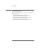
Chapter 3 Specifications Typical* power measurement uncertainty at 25°C for various input levels Graph 1. −10 dBm input level at 25°C. 3 Graph 2. 0 dBm and −20 dBm input * Typical means approximately 2/3 of all units will meet these characteristics.
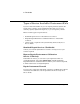
Chapter 3 Specifications Typical* power measurement uncertainty at −25 dBm input level Graph 3. 3 −25 dBm input level at 25°C. Graph 4. −25 dBm input level from * Typical means approximately 2/3 of all units will meet these characteristics.
Chapter 3 Specifications Timebase Frequency: 10 MHz Output: 10 MHz sine wave, 1 Vrms into 50 Ω External Timebase Input: 1, 2, 5, 10 MHz; 1 to 5 Vrms into 50 Ω Connector: BNC female located on rear panel Internal Timebase Stability TCXO (Standard) Oven (Option 001) — <1 x10⁻⁷ <5 x 10⁻¹⁰ <1.5 x 10⁻⁸ <1 x 10⁻⁹ <2 x 10⁻¹⁰ (±10%) <1 x 10⁻⁷ <1 x 10⁻¹⁰ Warm-up — <1 x10⁻⁸ within 5 min. after turn-on at 25°C <1 x 10⁻⁶ <1 x 10⁻⁸ Aging Rate Per Day Per Month Short Term (1 sec. avg.
3 Chapter 3 Specifications 3-8 Operating Guide
A Rack Mounting the Counter
Appendix A Rack Mounting the Counter Rack Mounting the Counter Rack Mounting the Counter You can mount the Counter in a standard 19-inch cabinet using one of two optional kits available from Agilent: • Option 1CM Rack Mount Kit (Agilent 53150-67001 Rack Adapter Kit) for single instrument (Half Module) rack mounting. Instructions and mounting hardware are included with the rack-mounting kit. • Agilent 5061-9694 Lock Link Kit for two-instrument, side-by-side rack mounting.
Appendix A Rack Mounting the Counter Rack Mounting the Counter OPTIONS 3 To rack-mount the Counter by itself, perform the steps shown in the following illustration. (Refer to the instructions that are provided with the Rack Adapter Kit for details.
Appendix A Rack Mounting the Counter Rack Mounting the Counter 4 To rack-mount the Counter with another instrument side-by-side, obtain the 5061-9694 Lock Link Kit. (Refer to the instructions that are provided with the Lock Link Kit for details.
B Messages
Appendix B Messages Overview Overview B The Agilent 53150A/151A/152A provides two types of messages that are displayed on the Counter’s front panel and/or sent over the RS-232 serial interface. The first type is status messages, which are displayed during normal operation. The second type is error messages, which are sent via RS-232 and/or displayed when the Counter detects an error during the Self-Test procedure or during normal operation.
Appendix B Messages Self-Test Messages Self-Test Messages Table 3-2. Self-Test Messages Message Description ROM TEST FAIL ROM TEST OK ROM failed read test. ROM passed read test. RAM DATA LINES OK RAM DATA ERROR RAM ADDR LINES OK RAM ADDR ERROR RAM TEST OK RAM data lines passed test. RAM data lines failed test. RAM address lines passed test. RAM address lines failed test. RAM tests completed with no errors detected.
Appendix B Messages Error Messages B Error Messages Table 3-3 lists and describes messages that are generated by the Counter during Self-Test or during operation to indicate that a problem has been detected. These messages are displayed on the Counter’s front-panel display and are also sent via the RS-232 serial output (note that, in many cases, the exact message text that is displayed on the front panel is a condensed form of the message that is sent via RS-232). Table 3-3.
Appendix B Messages Error Messages Table B-3. Error Messages (continued) Message Display RS-232 Description FRONT PANEL FAIL The front panel or its interconnecting cable are defective or not properly connected. FPANEL FAIL X FPGA FAIL X X A failure was detected in the FPGA (Field Programmable Gate Array). GPIB FAIL X X A failure was detected in the GPIB hardware. X A failure was detected in the heterodyne-path circuit.
Appendix B Messages B Error Messages B-6 Operating Guide
C Using the Battery Option
Appendix C Using the Battery Option Overview Overview C The Battery option (Option 002) allows you to operate the Counter away from a source of AC power using internal rechargeable batteries or the external DC (EXT DC) power connector on the rear panel. You can charge the batteries inside the Counter when you are not using it, if an AC power source is available. (To charge the batteries inside the Counter, it must be in Standby mode.
Appendix C Using the Battery Option Operating the Counter from a DC Power Source When all three segments of the battery annunciator are activated, the battery charge level is at 83% or more. When only two segments are activated, the charge level is approximately 50%, and when only the first segment is activated, the charge level is approximately 17%. A pair of fully charged batteries in good condition provides enough power to operate the Counter for approximately three hours at 25º C.
Appendix C Using the Battery Option Replacing the Batteries Made in U.S.A. with domestic and foreign content ISM 1-A OPTIONS 001 Oven Time Base 002 Battery Main ~ Power Reference 10 MHz Auxillary WARNING: In or Out To avold electric shock, do not remove covers. No user-serviceable parts inside. Refer all servicing to qualified personnel. This unit must be earth grounded. 11 TO 18 VDC AC POWER 100 – 130 VAC, 50/60/400 Hz 75 VA 220 – 240 VAC, 50/60 Hz 75 VA RS-232 C EXT DC FUSE 1.
Appendix C Using the Battery Option Replacing the Batteries The thumbscrews require a considerable amount of turning force, since they pull the battery sled partially out of the Counter and also extract the battery terminals from the battery connector as you turn them.
Appendix C Using the Battery Option Replacing the Batteries C 3 2 Mai n~ Po we r Re 1 fere 11 nc e 10 18 M with MHz In or Out TO ad e do mes tic Au xilla in an U.S d fo ry O reign P .A . co nten t 00 TIO 001 Ove NS 2B n at Ti VD C tery me W B AR NIN G: EX T DC RS -232 as To e do av noold No t re elec Re us mov tri c fe er Th r al-ser e coshoc vic ve k, LIN is un l serv rs it m icieabl . E FU VO us ng e pa t be to rts S LT FU E: AG ea qual insid rth ifie SE E: e.
Appendix C Using the Battery Option Replacing the Batteries 3 Holding one of the batteries so the battery terminals are to your right and the plus sign at the terminal end is facing away from you, insert the left-hand end of the battery into the taller end of the battery sled with the far side of the battery against the far side of the sled. Lower the right end of the battery into the sled, and push down on the battery until it is down as far as it can go.
Appendix C Using the Battery Option Charging the Batteries Charging the Batteries C The batteries are charged automatically whenever the instrument is connected to an AC power source and is in Standby mode. The amount of time required to fully charge the batteries is dependent on several factors, including the current charge level, the condition of the batteries, the ambient temperature, and the power source used for charging.
Appendix C Using the Battery Option Precautions Precautions Observe the following precautions when handling and charging the batteries: Do not attempt to use or charge the batteries when they are exposed to temperatures below –10º C (15º F) or above 40º C (105º F). (Most batteries of this type have an internal safety device that prevents them from operating outside of this temperature range.) • Charge the batteries only with a charger intended for this type of battery or inside the Counter.
Appendix C Using the Battery Option C Precautions C-10 Operating Guide
Index SYMBOLS (Freq Offset), 1-20 (Resol key), 2-45 A Operating Guide B backlight, 1-11 BATT VOLTAGE, 2-40 batteries, 2-43, C-4 battery annunciator, C-2 battery chamber, C-7 Battery compartment, 1-7 Battery Option, 2-43 Battery compartment, 1-7 battery voltage, 2-43 battery voltage level, 2-40 Battery option, 1-3, 1-5, 1-18, 2-40, C-2-4 BATT VOLTAGE, 2-40 batteries, C-4 battery chamber, C-7 battery charge-level annunciator, C-2 Battery charge-level indicator, 1-5 battery sled, C-4, C-5 Battery Voltage, 1
Index operating the Counter from a DC power source, C-3 operating the Counter from the batteries, C-2 rechargeable batteries, C-2 removing the batteries, C-4 replacing the batteries, C-4 battery sled, C-4, C-5 Battery Voltage, 1-14, 2-41, C-3 Battery Voltage (BATT VOLTAGE), 2-43 battery voltage level, 2-40 BAUD, 2-7, 2-40, 2-41 Baud rate, 1-14, 2-4, 2-41, 2-46 Index C cable impedance, 2-30 calibration, 2-43 Ch 1 annunciator, 2-13 CH 1 NO SIGNAL, B-2 Ch 2 annunciator, 2-12 CH 2 NO SIGNAL, B-2 CH1 LPF, 2-7
Index F Electro-Static Discharge, 1-17 electro-static discharge prevention procedure, 1-17 Enter key, 1-2, 1-14, 2-5 Error, 1-5 Error Messages, B-4 –12V FAIL, B-4 12V FAIL, B-4 –5V FAIL, B-4 ADC FAIL, B-4 EEP WRT FAIL, B-4 FPANEL FAIL, B-5 FPGA FAIL, B-5 GPIB FAIL, B-5 HET PATH FAIL, B-5 IIC FAIL, B-5 INSTCFG FAIL, B-5 OVERTEMP, B-5 PATH FAIL, B-4 PWR CAL FAIL, B-5 PWR CKT FAIL, B-5 RAM FAIL, B-5 SAV SET FAIL, B-5 SERVICE FAIL, B-5 THRS FAIL, B-4 THRS HET, B-4 THRS THRU, B-4 THRU FAIL, B-5 VCO/CNT FAIL, B
Index Index Display Power / dBm/W key, 1-2 Display Power key, 2-4, 2-10 Enter key, 1-2 Freq Offset key, 2-4 FREQ Offset On/Off key, 2-10 Gate indicator, 1-2 Gate LED indicator, 1-3 GPIB key, 2-10 LCD display, 1-2 Menu key, 2-4 Menus at a Glance, 1-4 Offset On/Off / Relative Frequency key, 1-2 Offset On/Off / Relative Power key, 1-2 Offset On/Off keys, 2-4 POWER Offset On/Off key, 2-10 Power/Standby switch, 1-2 Pwr Offset key, 2-4 Rate / Frequency Offset key, 1-2 Rate key, 2-4, 2-10 Rel Freq key, 2-10 Rel
Index L LCD display, 1-2, 1-11 backlight, 1-11 LED Display Annunciator, 1-5 left pointer, 1-6 Legend icons, 1-9 LO, 1-23 Lock Link Kit, A-2 LOSS, 2-36 loss value, 2-30 Low-Pass Filter, 2-40, 2-45 low-pass filter, 2-46 M Operating Guide N Navigating in the Menu and Changing Settings, 1-12, 2-41 noise, 2-46 non-volatile memory, 2-30, 2-40, 2-46 Number of Averages, 2-10 number of averages, 2-17, 2-18 Numeric Entry, 2-6 numeric entry, 2-5 numeric values, 2-5 O OFF, 2-7 offset function, 2-23 Offset On/Off /
Index Index Operating the Counter from a DC Power Source, C-3 Operating the Counter from the Batteries, C-2 Operation acknowledging messages, 2-9 changing states, 2-7 displaying the Menu, 1-12 function selection keys, 2-10 measuring frequency, 1-17, 2-12 measuring power, 1-22 measuring relative frequency, 2-20 measuring relative power, 1-24, 2-26 measuring relative frequency, 1-19 navigating in the Menu, 1-12 navigating in the menu and changing settings, 2-41 numeric entry, 2-6 offsetting a frequency meas
Index Power Offset, 1-24, 1-25, 2-45 Power Offset (POWER Offset On/Off key), 2-45 Power Offset Example, 2-27 Power Offset function, 1-24, 2-27 Power offset measurement, 2-10 POWER Offset On/Off key, 2-10, 2-45 Power switch, 1-10 Power/Standby switch, 1-2 power-correction profiles, 2-30 power-measurement function, 2-10 power-on self-test, 2-12 precision, 2-14, 2-17 PRESET, 2-40, 2-45 Preset, 1-14, 2-45 Pwr, 1-5 Pwr annunciator, 2-24 PWR CORR, 2-38 PWR CORR> OFF, 2-33 Pwr Offset, 1-5, 2-4, 2-27 Pwr Offset an
Index resolution, 2-14 Resolution (Resol) key, 2-45 Resolution / GPIB key, 1-2 Resolution setting, 2-14 resolution setting, 2-14, 2-15, 2-16 Resolution Setting Example, 2-15 right pointer, 1-6 RJ12, 1-7 Rmt, 1-5 routine maintenance, 2-43 RS-232, 2-40, B-3 RS-232 Interface Baud rate, 1-14 RS-232 Interface connector, 1-7 RS-232 serial port, 2-46 RS-232 Serial Port Data Rate (BAUD), 2-46 Index S SAVE, 2-40, 2-45, 2-46 Save and Recall functions, 2-46 Save Settings, 2-45 Save Settings (SAVE), 2-45 Save User S
Index U Unit of Measurement, 1-23 units of measurement annunciator group, 2-25 user setting, 2-40 Using Power Correction, 2-30 Using the Clear and Reset/Local Keys, 2-9 Using the Menu, 2-39 Using the Selection Keys, 2-5 V version number, 2-44 W W, mW, uW, 1-5, 2-24 Index Operating Guide Index-9
Index Index Index-10 Operating Guide
Service and Support Contacting Agilent Technologies: For more information about Agilent test and measurement products, applications, and services, visit our web site at http://www.agilent.com/services/English/index.html. Agilent’s Test and Measurement Fax Service for United States and Canada: Technical information for test and measurement products and services is available 24 hours a day, 7 days a week, by calling 1-800-800-5281.
Continued from front matter. . . Warranty (cont’d) Agilent does not warrant that the operation of Agilent products will be uninterrupted or error free. If Agilent is unable, within a reasonable time, to repair or replace any product to a condition as warranted, customer will be entitled to a refund of the purchase price upon prompt return of the product. Agilent products may contain remanufactured parts equivalent to new in performance or may have been subjected to incidental use.
DC.fm Page 1 Monday, July 22, 2002 10:51 AM DECLARATION OF CONFORMITY According to ISO/IEC Guide 22 and CEN/CENELEC EN 45014 Manufacturer’s Name: Agilent Technologies, Inc. Manufacturer’s Address: 5301 Stevens Creek Blvd Santa Clara, California 95051 U.S.A. Declares, that the product Product Name: Model Number: Product Options: CW Microwave Frequency Counter 53150A, 53151A, and 53152A This declaration covers all options of the above product.
DC.