User’s Guide 11970 SERIES HARMONIC MIXERS (K, A, Q, U, V, and W Models) Manufacturing Part Number: 11970-90031 Supersedes 11970-90030 Printed in USA October 2003 © Copyright 1992, 1999, 2001−2003 Agilent Technologies, Inc.
Notice The information contained in this document is subject to change without notice. Agilent Technologies makes no warranty of any kind with regard to this material, including but not limited to, the implied warranties of merchantability and fitness for a particular purpose. Agilent Technologies shall not be liable for errors contained herein or for incidental or consequential damages in connection with the furnishing, performance, or use of this material.
LIMITATION OF WARRANTY The foregoing warranty shall not apply to defects resulting from improper or inadequate maintenance by Buyer, Buyer-supplied software or interfacing, unauthorized modification or misuse, operation outside of the environmental specifications for the product, or improper site preparation or maintenance. NO OTHER WARRANTY IS EXPRESSED OR IMPLIED. AGILENT TECHNOLOGIES SPECIFICALLY DISCLAIMS THE IMPLIED WARRANTIES OF MERCHANTABILITY AND FITNESS FOR A PARTICULAR PURPOSE.
Contents General Information Introduction. . . . . . . . . . . . . . . . . . . . . . . . . . . . . . . . . . . . . . . . . . . . . . . . . . . . . . . . . . . . . . . . . . . . . . . . . . . 8 Mixers Covered by Manual . . . . . . . . . . . . . . . . . . . . . . . . . . . . . . . . . . . . . . . . . . . . . . . . . . . . . . . . . . . . . 8 11970 Series Harmonic Mixers. . . . . . . . . . . . . . . . . . . . . . . . . . . . . . . . . . . . . . . . . . . . . . . . . . . . . . . . . . 9 Options . . . . . . . .
Table of Contents Contents Specification . . . . . . . . . . . . . . . . . . . . . . . . . . . . . . . . . . . . . . . . . . . . . . . . . . . . . . . . . . . . . . . . . . . . . . . 68 Description . . . . . . . . . . . . . . . . . . . . . . . . . . . . . . . . . . . . . . . . . . . . . . . . . . . . . . . . . . . . . . . . . . . . . . . . 68 4. Service Maintenance . . . . . . . . . . . . . . . . . . . . . . . . . . . . . . . . . . . . . . . . . . . . . . . . . . . . . . . . . . . . . . . . . . . . . . .
General Information 1 General Information 7
General Information Introduction Introduction The Agilent Models 11970K, 11970A, 11970Q, 11970U, 11970V and 11970W are general-purpose harmonic mixers with very flat frequency response characteristics and low conversion loss. Collectively, they cover the frequency range of 18 to 110 GHz. The 11970K covers the 18 - 26. 5 GHz range; the 11970A, the 26.
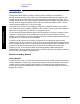
General Information Introduction 11970 Series Harmonic Mixers Figure 1-1. General Information Options Option 009, shown in Figure 1-2. is a Mixer Connection Kit. It includes three low-loss SMA cables (Part Number 5061-5458), one hex-head balldriver (Part Number 8710-1539) for tightening the waveguide connector screws, and one 5/16-inch open-end wrench (Part Number 8710-0510) for use on the SMA connectors.
General Information Introduction • PSA Series E4440A, E4446A, and E4448A spectrum analyzers require Option AYZ (LO OUT and IF IN connectors). The E4443A and E4445A do not support external mixing. General Information Figure 1-2.
General Information Specifications Specifications Specifications for the 11970 Series Mixers are listed in Table 1-1. These are the performance standards against which the mixers are tested (performance tests are provided in Chapter 3 ,“Performance Tests,”). Typical or nominal operating values are listed in Table 1-2. NOTE Supplemental characteristics are included only as additional information; they are not specifications. Equipment Supplied Five hex-head screws are supplied with each mixer.
General Information Specifications Table 1-1 11970 Series Specifications NOTE Unless otherwise stated, all specifications apply for an IF of 321.4 MHz and for RF input amplitudes of less than -20 dBm. General Information GENERAL LO Amplitude Range: 14 to 18 dBm1 Bias Requirements: None Calibration Accuracy: Maximum CW RF Input Level: 11970K/A/Q/U: ± 2.0 dB with LO amplitude range of 14.5 to 16 dBm 20 dBm (l00mW) 11970V/W: ± 2.2 dB with LO amplitude range of 14.
General Information Specifications Table 1-1 11970 Series Specifications NOTE Unless otherwise stated, all specifications apply for an IF of 321.4 MHz and for RF input amplitudes of less than -20 dBm. MODEL 11970K MODEL 11970A RF Frequency Range: 26.5 - 40 GHz LO Harmonic Number: 6 LO Harmonic Number: 8 LO Input Frequency Range: 2.95 - 4.36 GHz LO Input Frequency Range: 3.27 - 4.96 GHz Maximum Conversion Loss: 24 dB Maximum Conversion Loss: 26 dB 8566B Noise Level at 1 kHz Bandwidth, and 14.
General Information Specifications Table 1-1 11970 Series Specifications NOTE Unless otherwise stated, all specifications apply for an IF of 321.4 MHz and for RF input amplitudes of less than -20 dBm. General Information MODEL 11970V MODEL 11970W RF Frequency Range: 50 - 75 GHz RF Frequency Range: 75 - 110 GHz LO Harmonic Number: 14 LO Harmonic Number: 18 LO Input Frequency Range: 3.55 - 5.33 GHz LO Input Frequency Range: 4.15 - 6.
General Information Specifications Table 1-2 11970 Supplemental Characteristics NOTE Supplemental characteristics are included only as additional information; they are not specifications. Odd Order Mixing Product Suppression: 11970K/A/Q/U: >20 dB 11970V/W: >15 dB Spectrum Analyzer Absolute Amplitude Accuracy (using calibration data with a 14.5 to 16 dBm LO): 11970K, 18 - 26.5 GHz: ±3.2 dB 11970A, 26.5 - 40 GHz: ±3.2 dB 11970Q, 33 - 50 GHz: ±3.2 dB 11970U, 40 - 60 GHz: ±3.2 dB 11970V, 50 - 75 GHz: ±3.
General Information General Information Specifications 16 Chapter 1
Operation 2 Operation 17
Operation Introduction Introduction This section provides information on how to make effective use of the 11970 mixers. Operating Precautions Refer to the sections below for specific parameters to follow prior to mixer operation. WARNING Do not exceed the maximum ratings listed below or permanent damage to the mixer will result.
Operation Getting Started Getting Started The 11970 series of millimeter wave mixers have no bias or back-short adjustments. 11970 Mixers require an LO power of 14 to 18 dBm at the LO input. If the spectrum analyzer used with the 11970 does not have sufficient LO power, an 11975A Amplifier or an equivalent is required to increase this power. CAUTION Before connecting the 11975A Amplifier, set its rear panel ALC switch to ON. Failure to do this can damage the mixer.
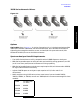
Operation Getting Started If you are using an 11970Q, 11970U, 11970V or 11970W Mixer, and the shoulder of its waveguide flange is not properly aligned with the flange of the device under test, amplitude measurement errors can result. To ensure proper alignment, tighten each of the four flange screws in turn by small amounts, moving clockwise around the flange.
Operation Using a Conversion-Loss Data Disk with the ESA or PSA Series Analyzers Using a Conversion-Loss Data Disk with the ESA or PSA Series Analyzers The conversion-loss data for your mixer can be quickly loaded in the memory of an ESA or PSA series analyzer from a floppy disk. The following process works with the floppy disk provided by the factory with your new mixer, or with one that you have stored the correction data.
Operation Using the Mixers with the E4407B Spectrum Analyzer (Option AYZ) Using the Mixers with the E4407B Spectrum Analyzer (Option AYZ) The Agilent Technologies E4407B spectrum analyzer contains an extensive menu of functions that help with millimeter measurements. The following examples explain how to connect external mixers to the spectrum analyzer, how to choose the band of interest, how to store and activate conversion-loss factors, and how to use the signal-identification functions.
Operation Using the Mixers with the E4407B Spectrum Analyzer (Option AYZ) 2. On the analyzer, press Preset, Factory Preset, if present. 3. Select external mixing by pressing Input/Output, Input Mixer, Input Mixer (Ext). 4. The analyzer frequency band will be set to 26.5 - 40 GHz (A). To choose a different band, press Ext Mix Band , then press the desired band frequency range/letter key. For this example, we will use band A, which ranges from 36.5 GHz to 40 GHz.
Operation Using the Mixers with the E4407B Spectrum Analyzer (Option AYZ) Signal Identification The IF output of a harmonic mixer will contain a signal at the intermediate frequency of the analyzer whenever the harmonic frequency of the LO and the frequency of the RF differ by the intermediate frequency. As a result, within a single harmonic band, a single input signal can produce multiple responses on the analyzer display, only one of which is valid (see Figure 2-3.).
Operation Using the Mixers with the E4407B Spectrum Analyzer (Option AYZ) Figure 2-4.
Operation Using the Mixers with the E4440A, E4446A, or E4448A PSA Series Spectrum Analyzer (Option AYZ) Using the Mixers with the E4440A, E4446A, or E4448A PSA Series Spectrum Analyzer (Option AYZ) Be sure to refer to “Spectrum Analyzer Retrofit Requirements” on page 9 for instrument requirements for the PSA Series spectrum analyzers. The Agilent Technologies PSA Series spectrum analyzers contain an extensive menu of functions that help with millimeter measurements.
Operation Using the Mixers with the E4440A, E4446A, or E4448A PSA Series Spectrum Analyzer (Option AYZ) 2. On the analyzer, press Preset, Factory Preset, if present. 3. Select external mixing by pressing Input/Output, Input Mixer, Input Mixer (Ext). 4. The analyzer frequency band will be set to 26.5 - 40 GHz (A). To choose a different band, press Ext Mix Band , then press the desired band frequency range/letter key. For this example, we will use band A, which ranges from 36.5 GHz to 40 GHz.
Operation Using the Mixers with the E4440A, E4446A, or E4448A PSA Series Spectrum Analyzer (Option AYZ) Signal Identification The IF output of a harmonic mixer will contain a signal at the intermediate frequency of the analyzer whenever the harmonic frequency of the LO and the frequency of the RF differ by the intermediate frequency. As a result, within a single harmonic band, a single input signal can produce multiple responses on the analyzer display, only one of which is valid (see Figure 2-6.).
Operation Using the Mixers with the E4440A, E4446A, or E4448A PSA Series Spectrum Analyzer (Option AYZ) Figure 2-7.
Operation Using the Mixers with the 856X Series Spectrum Analyzers Using the Mixers with the 856X Series Spectrum Analyzers External millimeter mixers can be used to extend the frequency coverage of the 8560 E-Series and EC-Series spectrum analyzers. (The 8560E/EC Option 002 and Option 327 do not have external mixing capability.) The 8560 E-Series and EC-Series spectrum analyzers contain an extensive menu of functions that help with millimeter measurements.
Operation Using the Mixers with the 856X Series Spectrum Analyzers Select the Frequency Band 2. Specify unpreselected external mixing by pressing CONFIG, then EXT MXR PRE UNPR until UNPR is selected. 3. To select a frequency above 18 GHz: a. Press AUX CTRL, EXTERNAL MIXER to set the analyzer to external mixer mode. b. Enter the desired frequency directly using the center-frequency function. c. Notice in Table 2-1 that some frequencies overlap and fall into two bands.
Operation Using the Mixers with the 856X Series Spectrum Analyzers In this example, we’ll look at U-band, which ranges from 40 GHz to 60 GHz, as shown in Figure 2-9. The LOCK HARMONIC function “locks” the spectrum analyzer in that band, ensuring that the spectrum analyzer sweeps only the chosen band. LOCK ON OFF is automatically set to ON when FULL BAND is pressed. Figure 2-9 Select the band of interest. Operation Save the average conversion-loss value 4.
Operation Using the Mixers with the 856X Series Spectrum Analyzers Figure 2-10 Store and correct for conversion loss. The second method for storing conversion-loss information lets you save individual conversion-loss data points at specific intervals across the harmonic band, using CNV LOSS VS FREQ. To view or enter a conversion-loss data point: b. Enter the conversion-loss data at the frequency shown. c. Use the step up ⇑ key to step through the band, entering the conversion loss at each step.
Operation Using the Mixers with the 856X Series Spectrum Analyzers Figure 2-11 Signal Responses Produced by a 50 GHz Signal in U Band Operation Identify signals with the frequency-shift method 6. Signal-identification routines that identify the signal and images are available on instruments with firmware revisions ≤920528, or with Option 008. The frequency-shift method of identifying valid signals uses the spectrum-analyzer function SIG ID ON OFF.
Operation Using the Mixers with the 856X Series Spectrum Analyzers Figure 2-12 Response for Invalid Signals Figure 2-13 Response for Valid Signals Operation Chapter 2 35
Operation Using the Mixers with the 856X Series Spectrum Analyzers Identify signals in wide frequency spans 7. SIG ID AT MKR identifies signals in wide frequency spans, using harmonic search. SIG ID AT MKR automatically determines the proper frequency of a signal and displays its value on the spectrum analyzer. • Activating SIG ID AT MKR on an image of the signal will yield a reading in the active block, as shown in Figure 2-14.
Operation Using the Mixers with the 856X Series Spectrum Analyzers Figure 2-15 SIG ID AT MKR Performed on a True Signal Operation Chapter 2 37
Operation Using the Mixers with MMS Analyzers Using the Mixers with MMS Analyzers Preliminary Operation NOTE This section provides information for the Agilent 70907A (or B), however the operation of the Agilent 70909A and Agilent 70910A is similar. Minor differences may be noted, but the necessary deviations from these exact instructions will be obvious.
Operation Using the Mixers with MMS Analyzers Operation Band Selection Use the following key sequence to enter the external mixing mode and to select the desired band of operation: MENU Select Input - choose external mixer input, for example: “IN 2 EM 70910A” State ext mixer fulband KAQUVE Press the softkey for the desired band. NOTE The above band selection key sequence must be used to enter the external mixing band of operation. Do not enter in the center frequency of the band directly.
Operation Using the Mixers with MMS Analyzers General Descriptions of Agilent 71000 Series Spectrum Analyzer External-Mixing Functions Allows access to the following softkey functions that control the measurement range when an external mixer extends the spectrum analyzer frequency range. The ext mixer softkey can be found under the State key. ext mixer fulband KAQUVE fulband WFDGYJ CONV LOSS SIGNAL IDENT fulband KAQUVE and Specify the frequency range for measurements made with external mixers.
Operation Using the Mixers with MMS Analyzers CONV LOSS (conversion loss) Offsets the reference level to compensate for amplitude losses at the active input port. If necessary, use select input to activate the desired input port before specifying its conversion-loss offset. To clear the offset, enter a conversion loss of zero. After the instrument preset, a default value of 30 dB is activated automatically for the input port of the external-mixer-interface module.
Operation Using the Mixers with MMS Analyzers NOTE See the table below for available frequency ranges and related harmonic numbers. Use the IMAGE N START and IMAGE N STOP softkeys for the image identification only. Table 2-3 Frequency Ranges and Corresponding Harmonic Numbers Band/Range Harmonic Number and Sign of IF (N) Internal Mixing - Agilent 71210C 2.9 - 6.2 6.0 - 12.7 12.5 - 19.9 19.7 - 22.0/26.5 −1 −2 +3 +4 Internal Mixing - Agilent 71200C 2.9 - 6.2 6.0 - 12.8 12.6 - 22.0 −1 −2 −4 18.0 26.
Operation Using the Mixers with MMS Analyzers Conversion Loss Versus Frequency Correction The Agilent 71000 Series Spectrum Analyzers with the Agilent 70907A (or B) External Mixer Interface Module installed has the amplitude-correction function (AMPCOR) available by remote programming. Use AMPCOR to compensate for the Agilent 11970 Series frequency-dependent conversion-loss variations.
Operation Using the Mixers with MMS Analyzers To print out an existing AMPCOR table, use the program listed below: 10 dim A$ (1:20) [30] 20 OUTPUT 718; “CONVLOSS 0DB;” 30 OUTPUT 718; “AMPCOR 50 GHZ, 46.1DB, 52GHZ, 46.7DB, 53GHZ,47.2DB;” 40 ! 50 OUTPUT 718; “AMPCOR?;” 60 ENTER 718 USING “%,k”;A$ (*) 70 ! 80 FOR I=1 TO 10 90 PRINT “Point “;I,A$ (I) 100 NEXT I 110 END Line 30: Generates an AMPCOR table. Line 60: % specifies that an EOI terminates the entire statement.
Operation Using the Mixers with the 8566B Spectrum Analyzer Using the Mixers with the 8566B Spectrum Analyzer Set up the equipment 1. Connect the external harmonic mixer to the spectrum analyzer, as shown in Figure 2-17. NOTE Good-quality shielded SMA-type cables should be used to connect the mixer to the spectrum analyzer to ensure that no signal attenuation occurs. Agilent 5061-5458 SMA-type cables may be used. Do not over-tighten the cables; the maximum torque should not exceed 112 N-cm (10 in-lb.).
Operation Using the Mixers with the 8566B Spectrum Analyzer “Harmonic 6L”, where “L” stands for locked, or you could press Shift+z to manually harmonic lock. Figure 2-18 TYPICAL MILLIMETER SIGNAL DISPLAY Operation A menu of millimeter measurement functions is accessed by pressing SHIFT, 1, MHz. Even though the spectrum analyzer is in an external mixer band, the 8566B spectrum analyzer retains full operation capability (except for use of the RF input attenuator and preselector).
Operation Using the Mixers with the 8566B Spectrum Analyzer Signal Identification Figure 2-18 shows a typical full-band display of a single input signal. Direct interpretation of the display is difficult because of the large number of responses produced by several local oscillator harmonics generated in the mixer. To solve this problem the 8566B spectrum analyzer uses two methods of signal identification.
Operation Using the Mixers with the 8566B Spectrum Analyzer Operation Figure 2-19 Sample Mixer Calibration Table 48 Chapter 2
3 Performance Tests Performance Tests 49
Performance Tests Introduction Introduction This section contains instructions for testing the performance of the 11970 Series Mixers. Performance tests are used to check the mixers at incoming inspection and for periodic evaluation. The tests verify the specifications listed for the mixers in Table 1-1. Test equipment required for the performance tests is listed in Table 3-1. for the 11970K, Table 3-2. for the 11970A, Table 3-3. for the 11970Q, Table 3-4. for the 11970U, Table 3-5.
Performance Tests Performance Test Procedures Performance Test Procedures Description Each performance test procedure is contained in a single paragraph. The first entry in each paragraph is the specification for the parameter being measured as described in Table 1-1 This is followed by a general description of the test and any special instructions or problem areas. Appropriate test setup illustrations are included in this section and are referenced in the procedures.
Performance Tests Performance Test Procedures Performance Tests Table 3-2. Recommended Test Equipment for 11970A Instrument Critical Specifications Recommended Model Spectrum Analyzer LO and IF ranges compatible with mixer 8566B Synthesized Sweeper Frequency: 8 to 13.5 GHz Output Level: >0 dBm 8340A Amplifier Output Level: >18 dBm leveled Frequency Range: 3 to 5 GHz 11975A Amplifier Frequency Range: 8 to 13.
Performance Tests Performance Test Procedures Table 3-3. Recommended Test Equipment for 11970Q Instrument Critical Specifications Recommended Model Spectrum Analyzer LO and IF ranges compatible with mixer 8566B Synthesized Sweeper Frequency: 11.0 to 16.7 GHz Output Level: >0 dBm 8340A Amplifier Output Level: >18 dBm leveled Frequency Range: 4 to 6 GHz 11975A Amplifier Frequency Range: 11.0 to 16.
Performance Tests Performance Test Procedures Performance Tests Table 3-4. Recommended Test Equipment for 11970U Instrument Critical Specifications Recommended Model Spectrum Analyzer LO and IF ranges compatible with mixer 8566B Synthesized Sweeper Frequency: 13.3 to 20 GHz Output Level: > 9 dBm 8340A Amplifier Output Level: > 18 dBm leveled Frequency Range: 4 to 6 GHz 11975A Amplifier Frequency Range: 13.
Performance Tests Performance Test Procedures Table 3-5.
Performance Tests Performance Test Procedures Table 3-6.
Performance Tests Conversion Loss and Frequency Response Conversion Loss and Frequency Response Specifications Conversion Loss: For a CW RF input power of less than -20 dBm 11970K: 24 dB maximum 11970A: 26 dB maximum 11970Q: 28 dB maximum 11970U: 28 dB maximum 11970V: 40 dB maximum 11970W: 47 dB maximum Frequency Response: For an LO amplitude between 14.5 and 16.0 dBm 11970K: ±1.9 dB 11970A: ±1.9 dB 11970Q: ±1.9 dB 11970U: ±1.9 dB 11970V: ±2.1 dB 11970W: ±3.0 dB For an LO amplitude between 14.0 and 18.
Performance Tests Conversion Loss and Frequency Response Description The frequency response and conversion loss are checked at four LO power levels. A known input power is applied to the input of the mixer. The IF output power is measured on the 8566B Spectrum Analyzer. From these measurements, the conversion loss and frequency response are calculated. 1. Connect an SMA cable from the 1st LO OUTPUT of the spectrum analyzer to the INPUT of the amplifier.
Performance Tests Conversion Loss and Frequency Response 11970V: 50.0 GHz 11970W: 75.
Performance Tests Conversion Loss and Frequency Response 9. Adjust the output power of the signal generator for a reading of approximately -10 dBm on the power meter for the 11970K, V or W and for approximately -3 dBm for the 11970A, Q or U. (Make sure that the unleveled light is not on for the 11970V and 11970W. Vary the power by adjusting the rotary vane attenuator.) 10.On the spectrum analyzer, press SHIFT and [MKR/∆ ⇑ STP SIZE]. 11.
Performance Tests Conversion Loss and Frequency Response Then press CENTER FREQUENCY: 11970K: 1, 8, GHz 11970A: 2, 6, [.] 5, GHz 11970Q: 3, 3, GHz 11970U: 4, 0, GHz 11970V: 5, 0, GHz 11970W: 7, 5, GHz 14.Press MARKER, PEAK SEARCH. If necessary, press MKR→CF and use DISPLAY LINE ENTER to find the average of the signal’s peak variations. (When testing 11970V or 11970W mixers, it is important to re-zero the power meter for each measurement.) 15.
Performance Tests Conversion Loss and Frequency Response or Conversion Loss = (-10.03 dBm) - (-0.232) - (-39.78 dBm) - 8.93 dB = 21.05 dB Performance Tests 17.Record the conversion loss in Table 3-7.
Performance Tests Conversion Loss and Frequency Response NOTE The conversion loss indicated on the mixer calibration label includes the loss in the IF cable. If other than the specified cable is used, then the loss in that cable must be compensated for when making amplitude measurements. 18.Increment the frequency of the signal generator 500 MHz higher. 19.Press DATA [↑], then PEAK SEARCH and MKR→CF on the spectrum analyzer. 20.
Performance Tests Conversion Loss and Frequency Response Performance Tests Figure 3-1 Performance Test Setups (1 of 2) 64 Chapter 3
Performance Tests Conversion Loss and Frequency Response Figure 3-2 Performance Test Setups (2 of 2) Performance Tests Chapter 3 65
Performance Tests Conversion Loss and Frequency Response Table 3-7 Conversion Loss and Frequency Response Test Record CONVERSION LOSS AND FREQUENCY RESPONSE for an LO POWER of_____________dBm Model Number____________ Date_____________ Serial Number______________Tested By _________________ Marker Amplitude Power Meter Readings Power Sensor Cal Factor Directional Coupler Coupling Factor Conversion Loss GHz dBm dBm % or dB dB dB Performance Tests Marker Frequency 66 Chapter 3
Performance Tests Conversion Loss and Frequency Response Table 3-7 Conversion Loss and Frequency Response Test Record CONVERSION LOSS AND FREQUENCY RESPONSE for an LO POWER of_____________dBm Marker Frequency Marker Amplitude Power Meter Readings Power Sensor Cal Factor Directional Coupler Coupling Factor Conversion Loss GHz dBm dBm % or dB dB dB Frequency Response = _______________dB Performance Tests Chapter 3 67
Performance Tests AVERAGE NOISE LEVEL TEST AVERAGE NOISE LEVEL TEST Specification 11970K: -110 dBm 11970A: -108 dBm 11970Q: -104 dBm 11970U: -104 dBm 11970V: -92 dBm 11970W: -85 dBm Description The average displayed noise level in a 1 kHz bandwidth, using external mixing with the 8566A/B Spectrum Analyzer, is checked at several LO power levels. This is accomplished by applying a known power to the input of the mixer. The difference between the amplitude of the known signal and the noise floor is measured.
Performance Tests AVERAGE NOISE LEVEL TEST 4. On the 11975A Amplifier, set the rear panel ALC switch to ON. Then connect the power sensor to the free end of the cable connected to the output of the amplifier. Set the power meter calibration factor to the value shown on the power sensor calibration label for 4 GHz. 5. Adjust the amplifier OUTPUT POWER LEVEL control for a reading of 14.5 ± 0.1 dBm on the power meter.
Performance Tests AVERAGE NOISE LEVEL TEST CAUTION Make sure the 8349A Amplifier, used in the signal generator system for 11970A, Q and U tests, is set for external leveling before you turn it on. Failure to set this amplifier for external leveling may allow the amplifier output to rise about 20 dBm, which is high enough to damage the frequency tripler. 6. Disconnect the power sensor and connect the equipment as shown in Figure 3-1. 7.
Performance Tests AVERAGE NOISE LEVEL TEST For 11970V: 5, 0, GHz For 11970W: 7, 5, GHz 10.Record the center frequency in Table 3-8. 11.Set the power meter CAL FACTOR to the value shown on the sensor calibration label for the center frequency indicated on the spectrum analyzer. 12.Set the signal generator output to produce a CW signal near the center of the spectrum analyzer display. Next, set the signal generator output power level to produce a reading of approximately -10 dBm on the power meter.
Performance Tests AVERAGE NOISE LEVEL TEST -104 dBm (for the 11970Q) -104 dBm (for the 11970U) -92 dBm (for the 11970V) -85 dBm (for the 11970W) 18.Enter the following push button commands on the 8566A/B: MARKER, OFF REFERENCE LEVEL, 0, dBm 19.Repeat steps 9 through 17 at the following center frequencies: 11970K: 22 and 26.5 GHz 11970A: 33 and 40 GHz 11970Q: 41 and 50 GHz 11970U: 50 and 60 GHz 11970V: 62 and 75 GHz 11970W: 92 and 110 GHz 20.Repeat steps 1 through 18 for a power level of 16.
Service 4 Service 73
Service Service Maintenance Maintenance The only maintenance required for the 11970 Series Mixers is preventive maintenance. When you are not using your mixer, cover its waveguide input with its waveguide cap. Also, though the 11970 Mixers can absorb more punishment than is normal for such devices, you should avoid subjecting them to unnecessary shock or vibration. Repairs The 11970 Mixers are NOT field-repairable. If your mixer fails, DO NOT try to repair it yourself, you will void the warranty.
Service Maintenance Service Figure 4-1 11970 Series Mixer Schematic Diagram Table 4-1 Model Chapter 4 LPF Fco (GHz) 11970K 4.4 11970A 5.0 11970Q 5.0 11970U 6.2 11970V 5.4 11970W 6.
Service Service Maintenance Table 4-2 Accessories and Replaceable Parts Part Number Description 5061-5460: Mixer Connector Kit (Option 009), includes the following three items: 5061-5458 Cable, 1 meter long, SMA male connectors (3 required) 8710-0510 Wrench, 5/16-inch, open-end 8710-1539 Ball Driver, 3/32-inch 3030-0221 Socket Head Cap Screw, 4-40 thread, .375 inches long (flange connecting screw for 11970K and 11970A) 1390-0671 Socket Head Cap Screw, captive, 4-40 thread, .
Service Maintenance Service Table 4-3 Agilent Technologies Sales and Service Offices UNITED STATES Instrument Support Center Agilent Technologies (800) 403-0801 EUROPEAN FIELD OPERATIONS Headquarters Agilent Technologies S.A. 150, Route du Nant-d’Avril 1217 Meyrin 2/ Geneva Switzerland (41 22) 780.
Service Service Maintenance 78 Chapter 4