USER’S GUIDE Agilent Technologies DC Electronic Loads Models N3300A, N3301A, N3302A, N3303A, N3304A, N3305A and N3306A Part No. 5964-8196 Microfiche No.
Warranty Information CERTIFICATION Agilent Technologies certifies that this product met its published specifications at time of shipment from the factory. Agilent Technologies further certifies that its calibration measurements are traceable to the United States National Institute of Standards and Technology, to the extent allowed by the Institute's calibration facility, and to the calibration facilities of other International Standards Organization members.
Safety Summary The following general safety precautions must be observed during all phases of operation of this instrument. Failure to comply with these precautions or with specific warnings elsewhere in this manual violates safety standards of design, manufacture, and intended use of the instrument. Agilent Technologies assumes no liability for the customer's failure to comply with these requirements. GENERAL This product is a Safety Class 1 instrument (provided with a protective earth terminal).
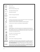
SAFETY SYMBOLS Direct current Alternating current Both direct and alternating current Three-phase alternating current Earth (ground) terminal Protective earth (ground) terminal Frame or chassis terminal Terminal is at earth potential. Used for measurement and control circuits designed to be operated with one terminal at earth potential. Terminal for Neutral conductor on permanently installed equipment Terminal for Line conductor on permanently installed equipment On (supply) Off (supply) Standby (supply).
Declaration Page DECLARATION OF CONFORMITY According to ISO/IEC Guide 22 and CEN/CENELEC EN 45014 Agilent Technologies, Inc. 140 Green Pond Road Rockaway, New Jersey 07866 U.S.A.
Acoustic Noise Information Herstellerbescheinigung Diese Information steht im Zusammenhang mit den Anforderungen der Maschinenlä minformationsverordnung vom 18 Januar 1991. * Schalldruckpegel Lp <70 dB(A) * Am Arbeitsplatz * Normaler Betrieb * Nach EN 27779 (Typprüfung). Manufacturer's Declaration This statement is provided to comply with the requirements of the German Sound Emission Directive, from 18 January 1991.
Table of Contents Warranty Information ........................................................................................................................................................... 2 Safety Summary...................................................................................................................................................................... 3 Declaration Page ...................................................................................................................
Cleaning ............................................................................................................................................................................. 37 Installing the Modules .......................................................................................................................................................... 38 Procedure........................................................................................................................................
PERFORMANCE TEST AND CALIBRATION PROCEDURES ............................................ 75 Introduction .......................................................................................................................................................................... 75 Equipment Required ............................................................................................................................................................ 75 Performance Tests ....................................
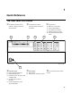
1 Quick Reference The Front Panel -At a Glance j15-character display shows k Annunciators indicate channel, voltage and current measurements. l System keys: operating modes and status conditions. 1 2 ♦ ♦ ♦ ♦ ♦ Return to Local mode. Set the GPIB address. Set the RS-232 interface. Display SCPI error codes. Save and recall instrument states.
1 - Quick Reference The Rear Panel At a Glance Q Control connector R Input binding post S GPIB connector 1 T RS-232 interface connector 2 3 4 5 7 U Power cord connector V Trigger/Digital connector W Sense switch Instrument Configuration Use the front panel Address menu to ♦ Select GPIB or RS-232 interface (see Chapter 5 in User's Guide). ♦ Select the GPIB bus address (see Chapter 5 in User's Guide). ♦ Configure the RS-232 interface (see Chapter 5 in User's Guide).
Quick Reference - 1 Front Panel Number Entry Enter numbers from the front panel as follows: Use the Entry Scroll keys to adjust the input setting in Meter mode. Meter AND Input Input If CC is lit, the input current changes. If CV is lit, the input voltage changes. If CR is lit, the input resistance changes. NOTE The input must be on for input values to change.
1 - Quick Reference Front Panel Annunciators φ1 A list is initiated or running. Prot CV The selected input channel is in the constant voltage (CV) mode. The selected input channel is in the constant current (CC) mode. The selected input channel is in the constant resistance (CR) mode. Cal The selected input channel is unregulated. The input is OFF. Press the Input on/off key to turn the input on. The selected input channel is enabled for transient operation.
Quick Reference - 1 Front Panel Menus - At a Glance Address R R R R Recall Shift Shift Shift Shift R Save Error Channel Sense R R R R R Func R R Protect R Meter R R R R R R R R R Current R R R R R R R Res R R R R R R R ADDRESS 5 INTF GPIB BAUDRATE 300 PARITY NONE FLOW NONE *RCL 0 *RST *SAV 0 ERROR 0 CHANNEL 1 S:PNT S:TIN S:WIN S:OFF S:C:RNG S:V:RNG FUNC FNC:MODE INP:SHOR OC -- -- -RRV --- -XXXX XXXX XXXX V MAX XXXX V MIN XXXX V RMS XXXX A MAX XXXX A MIN XXXX A RMS XXXX WATTS XXXX W MAX XXXX W MIN CURR
1 - Quick Reference Front Panel Menus - continued Voltage Tran R R R R R R R R R R R Trigger List R R R R R R R R R R R R R R R R R R R R R R R R R R R 16 VOLT V:MODE V:RANG V:SLEW V:SLW:N V:SLW:P V:TLEV V:TRIG TRAN T:DCYC T:FREQ T:MODE T:TWID INIT:IMMED ABORT LST:STEP LST:CNT DWEL:0 EOL CURR:0 EOL C:RANG:0 EOL C:SLEW:0 EOL C:SLW:N:0 EOL C:SLW:P:0 EOL C:TLEV:0 EOL FUNC:0 EOL RES:0 EOL R:RANG:0 EOL R:SLEW:0 EOL R:SLW:N:0 EOL R:SLW:P:0 EOL R:TLEV:0 EOL TRAN:0 EOL T:DCYC:0 EOL T:FREQ:0 EOL T:MODE:0 EOL T
Quick Reference - 1 SCPI Programming Commands - At a Glance NOTE ABORt CALibrate Most [optional] commands have been omitted for clarity. Refer to the Programming Guide for a complete description of all programming commands.
1 - Quick Reference SCPI Commands - continued STATus [SOURce:]LIST (continued) :VOLTage :CHANnel [:EVENt]? :CONDition? :ENABle :CSUMmary [:EVENt]? :ENABle :OPERation [:EVENt]? :CONDition? :ENABle :NTRansition :PTRansition :QUEStionable [:EVENt]? :CONDition? :ENABle [:LEVel] {,} :POINts? :RANGe {,} :POINts? :SLEW [:BOTH] {,} :POINts? :NEGative {,} : POSitive {,} :TLEVel {,} :POINts? RESistance [:LEVel] :TRIG :MODE :RANGe
2 General Information Document Orientation This manual describes the operation of the Agilent Model N3300A, N3301A, N3302A, N3303A N3304A, N3305A and N3306A DC Electronic Loads. Unless otherwise noted, all units will be referred to by the description "electronic load" throughout this manual. The following documents and software are shipped with your electronic load: ♦ A User's Guide (this document), contains installation, checkout and front panel information.
2 - General Information Safety Considerations This electronic load is a Safety Class 1 instrument, which means it has a protective earth terminal. That terminal must be connected to earth ground through power source equipped with a ground receptacle. Refer to the Safety Summary page at the beginning of this guide for general safety information. Before installation or operation, check the electronic load and review this guide for safety warnings and instructions.
General Information - 2 The N3301A is a DC Electronic Load Mainframe that is functionally identical to the N3300A, but is a half-rack width with only two slots for load modules. The mainframe can dissipate up to 300 watts per slot, to a total of 600 watts for a fully loaded mainframe. The N3302A, N3303A N3304A, N3305A and N3306A are electronic load modules that can be installed in the N3300A and N3301A mainframes.
2 - General Information Operating Modes The three modes of operation are: ♦ Constant current (CC). ♦ Constant voltage (CV). ♦ Constant resistance (CR). When programmed to a mode, a module remains in that mode until the mode is changed or until a fault condition, such as an overpower or overtemperature, occurs. The current, resistance, and voltage mode parameters described in subsequent paragraphs can be programmed whether or not the mode is presently selected.
General Information - 2 Triggered Current Level A current level can be preset (stored in the electronic load) allowing the input to be updated when a trigger is received instead of immediately as described above. If the CC mode is the active mode, the preset current level will become the actual value and the input will be updated when a trigger occurs.
2 - General Information Figure 2-2. Constant Resistance Mode Immediate Resistance Level The resistance level can be set at the front panel or via the GPIB (RES command). If the CR mode is active, the new setting immediately changes the input at a rate determined by the voltage or current slew setting (see description below). If the module is not in the CR mode, the new setting is saved for use when the mode is changed to CR.
General Information - 2 (VOLT:RANG command). When you program a voltage value, the electronic load automatically selects the range that corresponds to the value that you program. If the value falls in a region where ranges overlap, the electronic load selects the Low range. If the present input setting is outside the Low range, the electronic load will automatically adjust the input setting to the highest value available in the Low range.
2 - General Information Transient Operation Transient operation enables the module to periodically switch between two load levels, as might be required for testing power supplies. A power supply's regulation and transient characteristics can be evaluated by monitoring the supply's output voltage under varying combinations of load levels, frequency, duty cycle, and slew rate. Transient operation can be turned on and off at the front panel or via the GPIB (TRAN ON and TRAN OFF commands).
General Information - 2 List Operation List mode lets you generate complex sequences of input changes with rapid, precise timing, which may be synchronized with internal or external signals. This is useful when running test sequences with a minimum amount of programming overhead. You can program up to 50 settings (or steps) in the list, the time interval (dwell) that each setting is maintained, the number of times that the list will be executed, and how the settings change in response to triggers.
2 - General Information If the ac line is selected via the GPIB as the trigger source, triggers will be generated once for each cycle of ac input power. An ac line frequency of 60 Hz produces a trigger period of 16.67 ms; 50 Hz line frequency produces a trigger period of 20 ms. The rear-panel TRIGGER connector also provides a trigger output signal. This signal is generated synchronously with the trigger signal sent by the mainframe to the modules.
General Information - 2 Therefore, both minimum transition time and slew rate must be considered when determining the actual transition time. This is shown in Figure 2-8, which shows the minimum transition time for a given slew rate as a horizontal line, and at about a 13.3% or greater load change, the slew rate increases from the minimum transition time to the Maximum transition time at a 100% load change.
2 - General Information Input Control Short On/Off A module can simulate a short circuit at its input by turning the load on with full-scale current. The short circuit can be toggled on/off at the front panel using the SHORT command in the Func menu, or via the GPIB (INPUT:SHORT ON|OFF command). The short on/off change uses the slew rate setting of the active mode and range. The actual value of the electronic short is dependent on the mode and range that are active when the short is turned on.
General Information - 2 Caution To protect the electronic load from possible damage, the input voltage must not exceed the maximum input voltage rating specified in the module-specific pages supplied with each module. Never apply the ac line voltage to a module's input connectors. Overvoltage The overvoltage protection circuit is set at a predetermined voltage level, which cannot be changed.
2 - General Information remain set until they are reset. If the OT condition still exists when the reset is executed, the module's input will remain off. You must wait until the module cools down before you can reset the OT circuit. The fan(s) will continue to operate to cool the unit as quickly as possible. Reverse Voltage Caution This feature protects the load module in case the input dc voltage lines are connected with the wrong polarity.
General Information - 2 Saving and Recalling Settings The electronic load has internal registers in which settings (mode, current, voltage, resistance, slew, transient level, etc.) for each module can be saved. By saving settings and recalling them later you can save programming time. The present settings for all channels are saved in the specified register (0 to 9) at the front panel or via the GPIB (*SAV command). All of the settings are saved in the specified location in the mainframe's memory.
2 - General Information 20A Input (programmed via GPIB or front panel) ± 1V (2 V peak-peak) 1 kHz external programming signal The external programming signal (+ 1 and - 1 volt) corresponds to + 6 and - 6 amps at the input (1 volt external programming input = 1/10 full scale). Therefore, the input varies ± 6A at the 20A level. Fault The Fault signal becomes active if an overvoltage or reverse voltage occurs at the input, as described in the Protection Features paragraphs. Figure 2-9.
General Information - 2 As shipped from the factory, front panel measurements for input voltage and current are calculated from a total of 1000 readings taken at a 10 microsecond sampling rate. There are no trigger controls for front panel measurements. However, you can program both the sampling rate and the number of data points in each front panel measurement using commands in the Sense menu.
3 Installation Inspection Damage When you receive your electronic load, inspect it for any obvious damage that may have occurred during shipment. If there is damage, notify the shipping carrier and nearest Agilent Sales and Support Office immediately. The list of Agilent Sales and Support Offices is at the back of this guide. Warranty information is printed in the front of this guide.
3 - Installation Installing the Modules Procedure 1. With the mainframe off, disconnect the power cord and remove the top cover by loosening the screws with a flat-bladed screwdriver. 2. Remove any packing material from inside the mainframe. 3. Grasp the module using the quarter-turn locking fastener and the input connectors. This reduces the possibility of damage to static sensitive components on the pc board. 4. Start installing the modules in the slot next to the GPIB board (see figure 3-1).
Installation - 3 6. Connect the ribbon cable to the adjacent connector pins in the GPIB board (or adjacent module). Make sure the connectors are properly seated. 7. If applicable, install each module in the slot next to the previous module in the same manner (step 3 through 6). 8. Replace the top cover after all modules are installed. 9. Reconnect the power cord. Channel Number The channel number of a specific module is determined by the location of that module in relation to the GPIB board.
3 - Installation Figure 3-3A. N3300A Outline Diagram Figure 3-3B. N3301A Outline Diagram mm mm mm mm mm Figure 3-3C.
Installation - 3 Bench Operation A fan cools the electronic load by drawing air through the top and sides and exhausting it out the back. Minimum clearances for bench operation are 1 inch (25 mm) along the sides. Do not block the fan exhaust at the rear of the unit. Rack Mounting The N3300A electronic load can be mounted in a standard 19-inch rack panel or cabinet. Rack mount kits are available as Option 908 and 909 (with handles). Support rails are also required for rack mounting.
3 - Installation Input Connections Power Cord 1. Connect the power cord to the IEC 320 connector on the rear of the unit. If the wrong power cord was shipped with your unit, contact your nearest Agilent Sales and Support Office (refer to the list at the back of this guide) to obtain the correct cord. See Figure 3-5 for the part number and ordering options. Figure 3-5.
Installation - 3 Figure 3-6a. Manual Connector 1. Strip the back wire insulation as indicated Wire Size Strip back AWG 4 6 mm (0.65 in) AWG 6 or 8 13 mm (0.5 in) AWG 10 or smaller 10 mm (0.4 in) 2. AWG 4 is the maximum wire size. Stranded copper wire size, AWG 6 or 8 is the recommended wire. If you are connecting more than one wire on each connector, twist the wires to ensure a good contact when the adjustment knob is tightened. 3. Insert the wire into the connector.
3 - Installation conical washer (3050-1924) spacer (0380-4835) insulated wire lug (AMP 52266-3) spacer 4 AWG wire max. insert tabs cover (5040-1736) connector assembly with bolt (5040-1739) breakaway tab spacer wires exiting at bottom wires exiting at top tighten cover screw safety cover secured Figure 3-6b. 8mm Screw Terminal Connectors 1. Attach a connecting lug with an insulated ring terminal to the input wires. Connecting lugs must have an opening of at least 8mm in diameter.
Installation - 3 Wire Size AWG Table 3-2. Stranded Copper Wire Ampere Capacity Ampacity Notes: Cross Section Area in mm2 22 20 5.0 8.33 10 15.4 13.5 19.4 16 31.2 25 40 32 55 40 75 63 100 135 0.75 18 1 16 1.5 14 2.5 12 4 10 6 8 10 6 4 Wire Size AWG Cross Section Area in mm2 22 Ω/kft 40.1 10.16 0.75 26.7 6.388 1 16 20.0 4.018 1.5 14 13.7 2.526 2.5 12 8.21 1.589 4 10 5.09 0.9994 6 8 3.39 0.6285 10 6 1.95 0.3953 16 4 Ω/km 16.15 18 2.
3 - Installation Control Connector A 14-pin connector and a quick-disconnect mating plug are provided on each module for connecting remote sense leads, external V/I monitors, an external programming input, and external control lines (see figure 3-7). The mating plug is packaged in an envelope that is included with the module. Consistent with good engineering practice, all leads connected to the control connector should be twisted and shielded to maintain the instrument's specified performance.
Installation - 3 Sense Switch A local/remote sense switch is provided on each module. Unless you are using remote sensing, make sure that the sense switch is set to LCL (depressed). Remote sensing is used in certain applications to achieve greater accuracy (refer to Remote Sense Connections for more information).
3 - Installation Computer Connections The electronic load can be controlled through a GPIB interface or through an RS-232 interface. GPIB Interface Each electronic load has its own GPIB bus address, which can be set using the front panel Address key as described in Chapter 5. GPIB address data is stored in a non-volatile memory. The electronic load is shipped with its GPIB address set to 5.
Installation - 3 Application Connections Local Sense Connections Figure 3-10 illustrates a typical setup with module number 1 connected for constant current or constant resistance operation. Local sensing is used in applications where lead lengths are relatively short, or where load regulation is not critical. The sense switch must be set to LCL. Load leads should be bundled or tie-wrapped together to minimize inductance. N3300A Figure 3-10.
3 - Installation N3300A Figure 3-11. Remote Sensing N3300A Figure 3-12.
Installation - 3 In Figure 3-12, all lead connections are terminated at the source. Each module is connected to the source using separate wires. Using the source as the current distribution point allows larger wires to be used for each module connection and also reduces the common impedance inherent in daisy-chained configurations. If because of lead length or other considerations, lead connections cannot be made at the source, a remote distribution terminal may be required.
4 Turn-On Checkout Introduction Successful tests in this chapter provide a high degree of confidence that the electronic load is operating properly. For verification tests, see Appendix B. NOTE: This chapter provides a preliminary introduction to the electronic load front panel. See Chapter 5 for more detail. Checkout Procedure The tests in this section checks for proper operation of the electronic load. If you have not already done so, connect the power cord to the unit and plug it in.
4 - Turn-On Checkout 6. Depress the Meter key followed by the scroll key. 7. Repeat steps 3 through 6 for any other modules in the mainframe. 8. Turn off electronic load, disconnect power supply and continue with rear panel connections. NOTE: 1 50 W The display shows the computed input power for the selected channel. If the Err annunciator on the display is on, press the Shift key followed by the Error key to see the error number. See Table 4-2 for a list of errors.
5 Front Panel Operation Introduction Here is what you will find in this chapter: • A complete description of the front panel controls • Front panel programming examples. NOTE: The electronic load must be set in Local Mode to use the front panel controls. Press the Local key on the front panel to put the unit in Local Mode.
5 - Front Panel Operation jDisplay 15-character fluorescent display for showing measurements and programmed values. kAnnunciators Annunciators light to indicate operating modes and status conditions: φ1 A list is in progress CV The electronic load channel is in constant-voltage mode. CC The electronic load channel is in constant-current mode. CR The electronic load channel is in constant-resistance mode. Unr The electronic load channel is in an unregulated state.
Front Panel Operation - 5 System Keys Refer to the examples later in this chapter for more details on the use of these keys. SYSTEM Ident Local Error Address Save Recall Figure 5-2. System Keys This is the blue, unlabeled key, which is also shown as shift in this guide. Pressing this key accesses the alternate or shifted function key (such as ERROR). Release the key after you press it. The Shift annunciator is lit, indicating that the shifted keys are active.
5 - Front Panel Operation Function keys Refer to the examples later in this chapter for more details on the use of these keys. FUNCTION Sense Meter Step Func Channel Step Channel Current Prot Clear Protect Res List Tran Trigger Input on/off Voltage Trigger Control Figure 5-3. Function Keys Immediate Action Keys Immediate action keys immediately execute their corresponding function when pressed. Other function keys have commands underneath them that are accessed when the key is pressed.
Front Panel Operation - 5 Scrolling Keys Q R Scrolling keys let you move through the commands in the presently selected function menu. Press ▼ to bring up the next command in the list. Press ▲ to go back to the previous command in the list. Function menus are circular; you can return to the starting position by continuously pressing either key Q Step R Step These keys let you scroll through points in a list function. When the display indicates EOL, the end of the list has been reached.
5 - Front Panel Operation Input Control Keys Input control keys control the input functions of the electronic load. Shift Current Channel Press this key to select another channel. Enter the channel number using the Entry Keys. (This key performs the same function as ▼ Channel.) Press this key to access the current menu. Display CURR C:MODE C:RANG C:SLEW C:SLW:N C:SLW:P C:TLEV C:TRIG Res Press this key to access the resistance menu.
Front Panel Operation - 5 Transient Control Keys Transient control keys control the transient functions of the electronic load. Tran Press this key to access the function menu.
5 - Front Panel Operation Entry Keys 7 8 9 4 5 6 1 2 3 E - 0 . Input Input Enter Clear Entry Figure 5-4 Entry Keys Q Input These keys perform two functions. In Meter mode, these keys can be used to adjust the present input current, voltage, or resistance - depending on which function is presently active (indicated by the CC, CR, or CV annunciator). R Input In menu mode, these keys let you scroll through choices in a parameter list that apply to a specific command.
Front Panel Operation - 5 Examples of Front Panel Programming You will find these examples on the following pages: 1. Using the front panel display. 2. Programming constant current, voltage, and resistance modes. 3. Programming transient operation. 4. Programming lists. 5. Querying and Clearing Output Protection and Errors 6. Making basic front panel measurements 7. Setting GPIB address or RS-232 parameters. 8. Saving and recalling operating states.
5 - Front Panel Operation 10. On the Function keypad, press Input On/Off to turn input on. Dis annunciator off 11. To make minor changes to an existing value: On the Function keypad, press Current. On the Entry keypad, press QInput or R Input to scroll from 1.25 to 2.25. Then press Enter. CURR 2.25 Set the constant resistance mode input Action Display 1. On the Function keypad, press Q Channel to scroll through the channels until channel 1 appears on the display. 1 2.
Front Panel Operation - 5 3 - Programming Transient Operation Transient operation can be used in the CC, CR or CV mode. It causes the selected channel to switch between two load levels.
5 - Front Panel Operation Set transient operation for Pulse mode In this example, assume that the CC mode is active, the slew rate is at the factory default setting (maximum rate), and the applicable transient operation parameters have been set as follows: pulse mode, main current level = 5 A, transient current level = 10 A, pulse width = 1 millisecond. In this example, the electronic load starts conduction at the main current level setting (5 amps).
Front Panel Operation - 5 Figure 5-7. Toggled Transient Operation Action Display 1. On the Function keypad, press Current. On the Entry keypad, press 5 Enter . CURR 5 2. On the Function keypad, press Current. On the Function keypad, press • key until transient current is displayed. C:TLEV 3. On the Entry keypad press 10 Enter. C:TLEV 10 6. On the Function keypad, press Tran. On the Function keypad, press • key until transient mode is displayed. T:MODE 7.
5 - Front Panel Operation Trigger 1 0 2 3 4 List Count = 1 5 List Count = 2 Figure 5-8. List Sequence Action 4. Access the List menu again and press ‚ until you access the dwell time. This specifies the time for each current point, which is effectively its width. The first dwell point (0) appears in the display. On the Entry keypad, press 2 and Enter. 5. Pressing the Enter key automatically advances to the step in the list.
Front Panel Operation - 5 5 - Querying and Clearing Output Protection and Errors When overvoltage, overcurrent, or overtemperature condition occurs, the Prot annunciator on the front panel will be on and the electronic load will disable its output. Error messages can occur at any time during the operation of the unit. When the Err annunciator on the front panel is on, it means that either an error has occurred on the GPIB bus, or a selftest error has occurred.
5 - Front Panel Operation 1. Action Displays the minimum current Displays the rms voltage Displays the input power Displays the maximum power Displays the minimum power Use ‚ and • Display A MIN A RMS WATTS W MAX W MIN to scroll through the measurement selections 7 - Setting the GPIB Address Your electronic load is shipped with the GPIB address set to 5.
A Specifications Table A-1 lists the specifications for the different load models. Specifications indicate warranted performance in the 25°C ±5°C region of the operating temperature range. Specifications apply to normal and transient modes unless otherwise noted. Table A-1.
A - Specifications Table A-1.
Specifications - A Table A-2 lists the supplemental characteristics, which are not warranted but are descriptions of typical performance determined either by design or type testing. Table A-2.
A - Specifications Table A-2.
B Performance Test and Calibration Procedures Introduction This appendix contains test procedures for checking the operation and calibration of the Agilent N330xA Series Electronic Load Modules. The tests are performed using the front panel keypad of the N3300A or N3301A Mainframes. The required test equipment is listed in Table B-1 and sample performance test record cards are included at the end of the performance test section.
B - Performance Test and Calibration Performance Tests IMON Zero Verification This test verifies that IMON Zero is within calibration. IMON zero must be in calibration to perform the tests in this section. If the IMON value is not within calibration, go to the calibration section of this appendix and calibrate IMON zero, IPROG, current programming and readback and resistance programming and readback. See figure B-1 for IMON Zero test setup. 1. 2. 3. 4.
Performance Test and Calibration - B 6. Press [ CURR ] [ 1 ] ( except N3303A press [ CURR ] [ 0.1 ] ). Press [ CURR ]. Scroll until display reads C:RANG, press [ 1 ] [ Enter ]. Press shift key, [ Sense ] scroll till display reads S:C:RNG press [ 1 ] [ Enter ]. 7. Checking low current range, low input current Wait 10 seconds then record the actual input current ( DVM reading / current shunt resistance ) and front panel current reading on the test card under low current range low current. 8.
B - Performance Test and Calibration 4. Turn on the power source. Set the power source voltage and current to the values listed in the following table. Power Source Voltage Setting Power Source Current Setting N3302A 61V 2A N3303A 246V 0.6A N3304A 61V 3A N3305A 152V 2A N3306A 61V 3A 5. Checking high voltage range, high voltage point. Wait 10 seconds then record actual input voltage and front panel voltage reading on test record card under high voltage range, high voltage. 6.
Performance Test and Calibration - B CR Mode Tests These tests verify that the module operates in CR mode and the resistance programming is within specification.
B - Performance Test and Calibration 6. Set power source voltage and current values as listed in following table. Power Source Voltage Setting Power Source Current Setting 7. N3302A 24V 7A N3303A 96V 3A N3304A 12V 7A N3305A 30V 15A N3306A 12V 8A Wait 15 seconds. Calculate and record resistance range 2 high resistance point Resistance Range 3 Programming Accuracy 1. Press [ RES ].
Performance Test and Calibration - B 6. Set power source voltage and current values as listed in following table. Power Source Voltage Setting Power Source Current Setting 7. N3302A 50V 3.5A N3303A 96V 1A N3304A 20V 3A N3305A 50V 3.5A N3306A 20V 3.5A Wait 3 seconds. Calculate and record resistance range 4 high resistance point Transient Generator Mode Tests This test verifies that the transient generator frequency and duty cycle circuits are within specification.
B - Performance Test and Calibration Pulse Width Accuracy This test verifies that the transient generator pulse width accuracy is within specification. Note: Use the GPIB controller to generate a continuous pulse train. 1. Connect Electronic Load, Power Source, Current Probe and Oscilloscope as shown in figure B-5. 2. If using a controller, connect controller to Electronic Load mainframe rear panel GPIB connector. 3. Turn on the Electronic Load and press [Recall].
Performance Test and Calibration - B Agilent N3302A Verification Test Record Test Description Minimum Specification Constant Current Mode Tests 30 Ampere Range Programming and Readback 0.989 A Low Current ( 1 A ) Aout – 6.5mA Front Panel Display 29.960 A High Current ( 30 A ) Aout – 21mA Front Panel Display 3 Ampere Range Programming and Readback 0.994 A Low Current ( 1 A ) Aout – 3.5mA Front Panel Display 2.992 A High Current ( 3 A ) Aout – 4.5mA Front panel Display Constant Current Regulation Test 2.
B - Performance Test and Calibration Agilent N3303A Verification Test Record Test Description Minimum Specification Constant Current Mode Tests 10 Ampere Range Programming and Readback 0.9915 A Low Current ( 1 A ) Aout – 5.5mA Front Panel Display 9.9825 A High Current ( 10 A ) Aout – 10mA Front Panel Display 1 Ampere Range Programming and Readback 0.0959 A Low Current ( 0.1 A ) Aout – 2.55 mA Front Panel Display 0.
Performance Test and Calibration - B Agilent N3304A Verification Test Record Test Description Minimum Specification Constant Current Mode Tests 60 Ampere Range Programming and Readback 0984 A Low Current ( 1 A ) Aout –10.5mA Front Panel Display 59.925 A High Current ( 60 A ) Aout – 40mA Front Panel Display 6 Ampere Range Programming and Readback 0.9915 Low Current ( 1 A ) Aout – 5.5mA Front Panel Display 5.
B - Performance Test and Calibration Agilent N3305A Verification Test Record Test Description Minimum Specification Constant Current Mode Tests 60 Ampere Range Programming and Readback 0.984 A Low Current ( 1A ) Aout – 10.5mA Front Panel Display 59.925 A High Current ( 60 A ) Aout – 40mA Front Panel Display 6 Ampere Range Programming and Readback 0.9915 A Low Current ( 1A ) Aout – 5.5mA Front Panel Display 5.
Performance Test and Calibration - B Agilent N3306A Verification Test Record Test Description Minimum Specification Constant Current Mode Tests 120 Ampere Range Programming and Readback 0.9615 A Low Current ( 1A ) Aout – 20.5mA Front Panel Display 119.8425 A High Current ( 120 A ) Aout – 80mA Front Panel Display 12 Ampere Range Programming and Readback 0.9840A Low Current ( 1A ) Aout – 10.5mA Front Panel Display 11.
B - Performance Test and Calibration N330xA Module (top view) IMON_INV Location of I MON zero pins on single-slot modules GND_AQS Agilent 3458 or 34401 DVM A COM + IMON_INV I MON GND_AQS Ribbon Cable INPUT TERMINALS MUST BE OPEN Figure B-1.
Performance Test and Calibration - B N330xA Module + + _ Agilent 3458 or 34401 DVM _ Power Source -S +S Be sure sense switch is in RMT position Figure B-3. VOLTAGE CALIBRATION N330xA Module + + _ _ SHUNT -S +S Agilent 3458 or 34401 DVM Power Source Agilent 3458 or 34401 DVM If 2 DVM's are not available - move DVM between +/- sense and shunt as required by program Be sure sense switch is in RMT position Figure B-4.
B - Performance Test and Calibration Calibration Parameters Calibrated The following parameters may be calibrated. • External Current Monitor ( Imon ) • External Current Programming ( Iprog ) • Input Current • Input Voltage • Input Resistance You do not have to do a complete calibration each time. If appropriate, you may calibrate only the current, voltage or resistance and proceed to “Saving Calibration Constants”.
Performance Test and Calibration - B IMON, IPROG and CURRENT Calibration Program 10 20 30 40 50 60 70 80 90 100 110 120 130 140 150 160 170 180 190 200 210 220 230 240 250 260 270 280 290 300 310 320 330 340 350 360 370 380 390 400 410 420 430 440 450 460 470 480 490 500 510 520 530 ! This program will calibrate Imon, Iprog and Current ! for load modules N3302A, N3303A, N3304A, N3305A and N3306A.
B - Performance Test and Calibration 540 550 560 570 580 590 600 610 620 630 640 650 660 670 680 690 700 710 720 730 740 750 760 770 780 790 800 810 820 830 840 850 860 870 880 890 900 910 920 930 940 950 960 970 980 990 1000 1010 1020 1030 1040 1050 1060 1070 1080 1090 1100 92 INPUT "Enter value of high range current shunt in ohms",Rshunt DISP "You have entered ";Rshunt;" ohms" INPUT "If correct enter 'Y' or press CONT, if wrong enter 'N' or 'n'",Y$ IF UPC$(Y$)="Y" OR Y$="" THEN 590 IF UPC$(Y$)="N" OR Y$
Performance Test and Calibration - B 1110 1120 1130 1140 1150 1160 1170 1180 1190 1200 1210 1220 1230 1240 1250 1260 1270 1280 1290 1300 1310 1320 1330 1340 1350 1360 1370 1380 1390 1400 1410 1420 1430 1440 1470 1480 1490 1500 1510 1520 1530 1540 1550 1560 1570 1580 1590 1600 1610 1620 1630 1640 1650 1660 1670 1680 ! OUTPUT @Ld;"CAL:IPR:LEV P4" ! PRINT TABXY(20,20),"Calibrating IMON & IPROG P4 - 30 SECOND WAIT" WAIT 30 CLEAR SCREEN ! INPUT "Measure voltage across current shunt and enter in volts",Ip4 ! INP
B - Performance Test and Calibration 1690 1700 1710 1720 1730 1740 1750 1760 1770 1780 1790 1800 1810 1820 1830 1840 1850 1860 1870 1880 1890 1900 1910 1920 1930 1940 1950 1960 1970 1980 1990 2000 2010 2020 94 CLEAR SCREEN ! OUTPUT @Ld;"INP:STAT ON" OUTPUT @Ld;"CAL:LEV P1" ! PRINT TABXY(10,10),"Calibrating low current range P1 - 30 SECOND WAIT" WAIT 30 CLEAR SCREEN ! INPUT "Measure voltage across current shunt and enter in volts",Ip1 ! Ip1=Ip1/Rshunt ! OUTPUT @Ld;"CAL:DATA ";Ip1 ! OUTPUT @Ld;"CAL:LEV P2"
Performance Test and Calibration - B VOLTAGE Calibration Program 10 20 30 40 50 60 70 80 90 100 110 120 130 140 150 160 170 180 190 200 210 220 230 240 250 260 270 280 290 300 310 320 330 340 350 360 370 380 390 400 410 420 430 440 450 460 470 480 490 500 510 520 530 ! This program calibrates the voltage mode for load modules ! N3302A, N3303A, N3304A, N3305A and N3306A.
B - Performance Test and Calibration 540 550 560 570 580 590 600 610 620 630 640 650 660 670 680 690 700 710 720 730 96 ! INPUT "Measure voltage at +/- sense terminals and enter value in volts",Vp1 ! OUTPUT @Ld;"CAL:DATA";Vp1 ! OUTPUT @Ld;"CAL:LEV P2" WAIT 1 ! INPUT "Measure voltage at +/- sense terminals and enter value in volts",Vp2 ! OUTPUT @Ld;"CAL:DATA";Vp2 ! OUTPUT @Ld;"CAL:SAVE" OUTPUT @Ld;"CAL:STAT OFF" ! CLEAR SCREEN PRINT "Voltage calibration adjustments complete" PRINT "Verify Voltage Adjustmen
Performance Test and Calibration - B RESISTANCE Calibration Program 10 20 30 40 50 60 70 80 90 100 110 120 130 140 150 160 170 180 190 200 210 220 230 240 250 260 270 280 290 300 310 320 330 340 350 360 370 380 390 400 410 420 430 440 450 460 470 480 490 500 510 520 530 540 ! This program calibrates the resistance mode ! for load modules N3302A, N3303A, N3304A, N3305A and N3306A.
B - Performance Test and Calibration 550 560 570 580 590 600 610 620 630 640 650 660 670 680 690 700 710 720 730 740 750 760 770 780 790 800 810 820 830 840 850 860 870 880 890 900 910 920 930 940 950 960 970 980 990 1010 1020 1030 1040 1050 1060 1070 98 PRINT TABXY(10,12);"Set power source to voltage and current settings from Table B-2" PRINT TABXY(10,13);"for resistance range 1 - Point P2" DISP "Press Cont to continue resistance range 1 calibration" PAUSE OUTPUT @Ld;"CAL:LEV P2" CLEAR SCREEN PRINT TABXY
Performance Test and Calibration - B 1080 1090 1100 1110 1120 1130 1140 1150 1160 1170 1180 1190 1200 1210 1220 1230 1240 1250 1260 1270 1280 1290 1300 1310 1320 1330 1340 1350 1360 1370 1380 1390 1400 1410 1420 1430 1440 1450 1460 1470 1480 1490 1500 1510 1520 1530 1540 1550 1560 1580 1590 1600 1610 Rp2=Vt2/Ip2 OUTPUT @Ld;"CAL:DATA";Rp2 OUTPUT @Ld;"INP:STAT OFF" ! ! ************ CALIBRATING RANGE 3 ****************** ! CLEAR SCREEN INPUT "Enter value of current shunt for range 3 in OHMS",Rshunt3 PRINT TAB
B - Performance Test and Calibration 1620 1630 1640 1650 1660 1670 1680 1690 1700 1710 1720 1730 1740 1750 1760 1770 1780 1790 1800 1810 1820 1830 1850 1860 1870 1880 1890 1900 1910 1920 1930 1940 1950 1960 1970 1980 1990 2000 2010 2020 100 CLEAR SCREEN ! PRINT TABXY(10,12);"Set power source to voltage and current settings from" PRINT TABXY(10,13);"Table B-1 for resistance range 4 - Point P1" DISP "Press CONT when ready to calibrate resistance range 4" PAUSE CLEAR SCREEN PRINT TABXY(9,15);"CALIBRATING RES
Index -- -- -- -- --, 69 0 0 ...
Index G GPIB, 70 address, 70 connections, 48 ground, earth, 20 guide, user’s, 19 H history, 6 P port, 34 power cord, 37, 42 power measurements, 35 power receptacle, 20 print date, 6 programming errors, 32 programming lists, 67 programming transinets, 65 protection OV, 68 I input current setting, 63 resistance setting, 63 voltage setting, 63 input measurements, 34 input on/off, 30, 58 inspection, 37 installing modules, 38 query protection, 68 R L List, 67 list mode, 27 location, 40 low voltage operati
Index Address, 57 Error, 57 Interface, 57 Local, 57 RCL, 57 Save, 57 Shift, 57 V verification equipment, 75 voltage range, 24 triggered, 25 VXIplug&play, 19 T transient, 26 continuous, 26 pulse, 26 toggled, 26 transients continuous mode, 65 pulse mode, 66 toggled mode, 66 trigger connector, 47 trigger mode, 27 W warranty, 2 wire current ratings, 44 Z zero-volt operation, 51 103
Agilent Sales and Support Office For more information about Agilent Technologies test and measurement products, applications, services, and for a current sales office listing, visit our web site: http://www.agilent.com/find/tmdir You can also contact one of the following centers and ask for a test and measurement sales representative. United States: Agilent Technologies Test and Measurement Call Center P.O.
Manual Updates The following updates have been made to this manual since its publication. 6/1/01 Table 2-1 has been updated with new option part numbers. Information about Option UJ1 has been added to chapters 2 and 3. Information about Low Voltage Operation has been has been added to the end of chapter 3.