
User's Manual


102
Output impedance is l0K ohm: the monitoring device input impedance should be at least 1M ohm to limit error to
1% + basic accuracy; 10M ohm to limit error to 0.1% + basic accuracy.
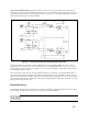
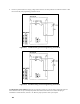
The I. MON signal from the mainframe is also brought out through the 002 Option board. A 0 to full scale current-
monitor output is available between pins J3-3 (I. MON) and J3-1 (D COMMON). Output impedance is l0K ohms:
the monitoring device input impedance should be at least 1M ohm to limit error to 1% + basic accuracy.
In some applications it may be desirable to install a noise-suppression capacitor on these monitor outputs to lessen
the effects of noise induced in the monitor leads. The capacitors should be ceramic or tantalum type, from 0.1 to
1
µF. The capacitor is installed directly across the monitor device input terminals .
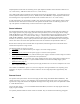
Status Indicators
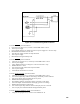
Six optically isolated lines provide open collector digital outputs which indicate certain modes and conditions of
power supply operation. For proper supply operation of the opto-isolators, the user must supply the bias voltage,
(ISOLATOR BIAS). This voltage can be from +4.75 V to + 16V depending upon the user's interface circuits, refer
to the specifications Table A-1. Connect the bias voltage ( + ) between J3-37, (ISOLATOR BIAS) and J3-34
(ISOLATOR COMMON). The status indicator outputs are open collector (referenced to ISOLATOR common);
therefore, it is necessary to connect a pull-up resistor from each output to ISOLATOR BIAS. When choosing the
resistor value observe the current sink capabilities of these lines as described in the Specifications Table A-1.
Because of the relatively slow rise and fall times of opto-isolators, Schmitt-triggered devices should be used to
interface these output lines to logic circuits.
The following signals are in active low-form:
a.
MODECV , J3-36, indicates that the power supply is in constant voltage operation.
b.
MODECC , J3-35, indicates that the power supply is in constant current operation.
c.
DUNREGULATEOUTPUT , J3-18, indicates that the power supply is in neither constant voltage nor constant
current operation and cannot be guaranteed to meet specifications.
d.
EOVERVOLTAG , J3-17, Indicates power supply shutdown because of: the voltage output exceeding the OV
trip point set at the front panel; or, a system-initiated shutdown as described in multiple supply system
shutdown section, page 103.
e.
ATUREOVERTEMPER , J3-16, indicates power supply shutdown due to an excessive temperature rise on the
FET or output diode heatsink.
The Low Bias AC DROPOUT signal, J3-19, is in active high form. This signal indicates: loss of primary power,
momentary AC dropout. or "brownout'' conditions where the AC line voltage drops below approximately 70%
nominal.
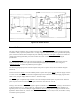
Remote Control
For operation of the opto-isolators. the user must supply the bias voltage (CONTROL ISOLATOR BIAS). This
voltage can be from + 4.75V to + 16V depending on the requirements of the driving circuits. The type of driving
logic and bias voltage will determine the amplitude of the high and low logic levels, refer to the Specification Table
A-1 under Remote Control.
Connect the bias voltage ( + ) to J3-10 CONTROL ISOLATOR BIAS, and reference the input signals to this bias
supply's negative terminal.
Two optically isolated methods of remote control are available. They are described in the following paragraphs.