
User's Manual


105
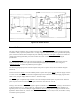
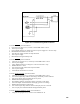
AC Dropout Buffer Circuit
This circuit couples, inverts and isolates the DROPOUT signal (received from the A2 Control Board) of status
output terminal J3-19 (
DROPOUT ). The dropout signal indicates loss of primary power, momentary AC dropout,
or "brownout" conditions where the AC line voltage drops below approximately 70% normal. The following
paragraph provides a brief description of the AC Dropout Buffer circuit. Refer to the Schematic Diagram
The AC Dropout Buffer Circuit receives a
DROPOUT signal from the A2 Control Board. This causes the bias
voltage supplied to the Dropout Buffer U14A to be pulled down through diode CR4 thus, turning U14A off. This in
turn will cause opto-isolator U3 to turn off. Since external pull up resistors are used, terminal J3-19 (DROPOUT)
will go high and remain high until the dropout signal from the A2 Control Board is removed.
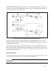
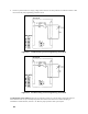
Multiple Supply System Shutdown
When using more than one 002 Option equipped power supply in a system, it may be desirable to implement a
system shutdown. In this configuration, an OVP trip or remote shutdown of a single unit will cause all of the
supplies to shut down.
Figure A-9. System Shutdown using Controller Power Supply
Figure A-9 shows one method of system shutdown. The advantages of this method are that one common is used for
all status and control lines (useful for controller-operated systems), and the capability of system reset. As shown in
Figure A-9, one supply's
EOVERVOLTAG line is connected to the next supply's TRIPREMOTE line, and so on
in a continuous chain.
Note +5V REG/POWER SUPPLY common from Supply 1 can be used instead of the bias voltage from
the controller. However, because of current limits of the + 5V REG, no more than four units can
be connected together in this configuration. To prevent ground loops, do not parallel connect + 5V
REG from more than one supply.
The note on page 101 tells how to determine if a shutdown was initiated through the remote trip line or by a supply's
OVP. This allows the controller to determine which supply initiated the shutdown. Following a multiple supply
shutdown, each unit can be reset individually or all the REMOTE RESET lines can be tied together for a system reset.