
User's Manual


114
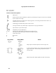
Logic Symbols and Definitions
High = more positive
Low = less positive
Indicator and Qualifier Symbols
OR function
Polarity indicator, shown outside logic symbol. Any marked input or output is active low; any unmarked
input or output is active high.
(Dynamic indicator) Any market input is edge-triggered, ie, active during transition between states. Any
unmarked input is level sensitive.
(Schmitt trigger) indicates that hysteresis exists in device.
(Non-logic indicator) Any marked input or output does not carry logic information.
Open-collector or open emitter output.
Monostable (one-shot) multivibrator.
t = xSec Indicates pulse width usually determined by external RC network.
G Gate input (a number following G indicates which inputs are gated).
C Control input (clock).
R Reset (clear).
SSet.
OLD SYMBOL NEW SYMBOL NOTES
Output requires external components to achieve logic state.
A positive-going transition at A or a negative-going transition at B
triggers the one-shot. External timing components connect to
non-logic inputs.
Output changes state rapidly regardless of input rate of change.