I DUAL OUTPUT POWER SUPPLY Agilent MODEL E3630A OPERATING AND SERVICE MANUAL FOR INSTRUMENTS WITH SERIAL NUMBERS KR85014528 AND ABOVE For instruments with Serial Numbers above KR85014528, a change page may be included. Manual Part No.
SAFETY SUMMARY The following general safety precautions must be observed during all phases of operation, service, and repair of this instrument. Failure to comply with these precautions or with specific warnings elsewhere in this manual violates safety standards of design, manufacture, and intended use of the instrument. Agilent Technologies assumes no liability for the customer's failure to comply with these requirements. SAFETY SYMBOLS BEFORE APPLYING POWER.
Table of Contents SAFETY SUMMARY . . . . . . . . . . . . . . . . . . . . . . . . . . . . . . . . . . . . . . . . . . . . . . . . . . . . . . . . . . . . . . 1-2 GENERAL INFORMATION . . . . . . . . . . . . . . . . . . . . . . . . . . . . . . . . . . . . . . . . . . . . . . . . . . . . . . . . . 1-4 INTRODUCTION. . . . . . . . . . . . . . . . . . . . . . . . . . . . . . . . . . . . . . . . . . . . . . . . . . . . . . . . . . . . . . . . 1-4 SAFETY CONSIDERATIONS . . . . . . . . . . . . . . . . . . . . . . . .
GENERAL INFORMATION between your instrument and the instrument described by this manual. The Change Sheet may also contain information for correcting errors in the manual. INTRODUCTION This section contains general information concerning the E3630A triple output power supply. Included are safety considerations, safety and EMC requirements, instrument and manual identification, option and accessory information, instrument description, and specifications. OPTIONS SAFETY CONSIDERATIONS Option No.
mode. In this mode the voltage of the negative output can be set lower than that of the positive output. The tracking ratio control allows the negative supply's output to be set to any value between a maximum that is within ±5% of the positive supply's output and a minimum that is less than 0.5 volts.
INSTALLATION cord plug appropriate for the user's location. Notify the nearest Agilent Sales and Service Office if the appropriate power cord is not included with the supply. INITIAL INSPECTION Before shipment, this instrument was inspected and found to be free of mechanical and electrical defects. As soon as the instrument is unpacked, inspect for any damage that may have occurred in transit. Save all packing materials until the inspection is completed.
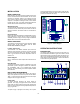
tor the 0 to 40V output voltage, add the voltmeter readings of the +20V and -20V output and use either the +20V or the 20V meter to measure the current. Before applying power to the supply, check the label on the heat sink to make certain that the supply's line voltage option agrees with the line voltage to be used. If the option does not correspond to your line voltage, refer to paragraph "LINE VOLTAGE OPTION CONVERSION" in the service section before applying power.
necessary to fulfill the total current demand. Series Operation Series operation of two or more power supplies can be accomplished up to the output isolation rating of any one supply to obtain a higher voltage than that available from a single supply. Series connected supplies can be operated with one load across both supplies or with a separate load for each supply.
Figure 4.
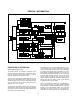
SERVICE INFORMATION Figure A-1. Block Diagram PRINCIPLES OF OPERATION By comparing its output to a high-stability reference, the 0 to +6-volt regulator holds its output voltage at the value determined by a front panel control. Any error in the actual output as compared to the desired output is amplified by an operational amplifier and applied as feedback to control the conduction of a series regulator transistor.
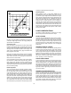
put is enclosed by a heavy line in Figure 3 of the operating section. If the operating point reaches the diagonal current limit line, a decrease in load resistance moves the operating point down the line, reducing the output voltage and current. Current foldback is controlled by a second operational amplifier (current comparison amplifier) in the regulator that monitors the dc output current.
Table A-1. Test Equipment Required (Cont’d) Current Sampling Resistor (Shunt) 100 mΩ 0.1% 15 W Measure output current Variable Voltage Auto Transformer Range : 85-130 and 200-260 Volts Vary ac input. General Measurement Techniques Operation Verification Tests The following tests assure that the power supply is performing properly. They do not, however, check all the specified parameters tested in the complete performance test described below. Proceed as follows: a.
Output Current Measurement. For accurate output current measurements, a current sampling resistor should be inserted between the load and the output of the supply. To simplify grounding problems, one end of this sampling resistor should be connected to the same output terminal of the supply which will be shorted to ground. An accurate voltmeter is then placed across the sampling resistor and the output current calculated by dividing the voltage across the sampling resistor by its ohmic value.
Line Regulation (Source Effect) Current Limit k. Disconnect all loads from the supply. l. Connect the test setup shown in Figure A-5 to the +20volt output. Substitute a short for RL and leave the load circuit switch open. m. Set the voltage of the ±20V supplies to 20 volts. n. Close the load switch and determine the current flow through the current sampling resistor (meter shunt) by measuring its voltage drop with the DVM. The current should be 0.55A±5% (0.5225A to 0.5775A). o.
Peak-to-Peak Measurement The peak-to-peak measurement is particularly important for applications where noise spikes could be detrimental to a sensitive load, such as logic circuitry. d. Turn on the supply. e. Record the voltage across RS and convert it to current by dividing this voltage by RS. f. Check that the current is less than 1 A. To measure the ripple and noise of the peak-to-peak value on each output supply output: a.
Stability (Drift) Definition: The change in output voltage (dc to 20 Hz) for the first 8 hours following a 30-minute warm-up period with constant input line voltage, constant load resistance and constant ambient temperature. Before applying power to the supply, make certain that its line voltage selector switch (S2) is set for the line voltage to be used. To measure the stability: a. Connect the test equipment across the output of the +20V supply as shown in Figure A-6. b.
Table A-3. Initial Trobleshooting Procedure STEP 1 ACTION Check output voltage of +20V supply. RESPONSE a. Normal b. Zero volts c. 2 Check output voltage of -20V supply in fixed tracking ratio mode. NEXT ACTION a. Proceed to step (2). b. Check ac line fuse (F1). If blown, proceed to "Open Fuse Troubleshooting" paragraph. If not blown, check bias and reference voltages (Table A-4). Output voltage lower or c. Check bias and reference voltages (Table A-4). higher than rating a. Normal b.
Table A-5. +20V Supply Troubleshooting (Cont’d) Low output voltage (lower than rating) 1. Measure voltage at the a. Measured voltage is less than 0 base of Q5. volt. b. Measures voltage is more than 0 volt. a. Check for open Q9, Q6, R26, or CR5. b. Proceed to step (2). 2. Eliminate current limit a. Output voltage increases. circuit as a source of b. Output voltage remains low. trouble by disconnecting anode of CR11. a. Check for U6B defective. b. Reconnect lead and proceed to step (3). 3.
Table A-7. +6V Supply Troubleshooting SYMPTOM STEP - ACTION RESPONSE PROBABLE CAUSE The +20V supply must operate properly before troubleshooting the -20V supply. High output voltage (higher than rating) 1. Attempt to turn off Q1 by a. Output voltage remains high. a. Q1 shorted. shorting emitter-to-base b. Output voltage becomes near zero b. Remove short and proceed to of Q1. volt. step 2. 2. Measure voltage at base of Q4. Low output voltage (lower than rating) 1. Measure voltage at the base of Q4.
ADJUSTMENT AND CALIBRATION c. Current Limit Adjustment +6V Supply. To adjust the current limit circuit in the +6V supply, proceed as follows: a. Check the setting of the current limit by performing steps (p) and (q) on page A-5. (Be sure to set the output voltage to 6 volts.) If reducing the load resistance permits the current to exceed 2.9 A, stop, turn R6 slightly clockwise, and repeat the test. If, instead, the current begins to fall before it reaches 2.
REPLACEABLE PARTS Table A-10. Reference Designators INTRODUCTION A C CR DS F G J L Q R S T TP VR U W This section contains information for ordering replacement parts. Table A-12 lists parts by reference designators and provides the following information: a. b. c. d. e. f. Reference designators. Refer to Table A-10. Agilent Technologies Part Number. Total quantity used in that assembly. Description. Manufacturer's supply code number. Refer to Table A-11 for manufacturer's name and address.
REFERENCE DESIGNATION PART NUMBER Q'TY DESCRIPTION MFR.
REFERENCE DESIGNATION PART NUMBER Q'TY DESCRIPTION MFR.
REFERENCE DESIGNATION PART NUMBER Q'TY DESCRIPTION & * ' & + * MFR. CODE MFR.
REFERENCE DESIGNATION PART NUMBER Q'TY DESCRIPTION MFR. CODE , !! & ! ! , !! & ! ! & $ % # ! # & MFR.
I CERTIFICATION Agilent Technologies certifies that this product met its published specifications at time of shipment from the factory. Agilent Technologies further certifies that its calibration measurements are traceable to the United States National Institute of Standards and Technology (formerly National Bureau of Standards), to the extent allowed by that organization's calibration facility, and to the calibration facilities of other International Standards Organization members.
DECLARATION OF CONFORMITY according to ISO/IEC Guide 22 and EN 45014 Manufacturer’s Name: Agilent Technologies, Inc.