8472B Crystal Detector Operating and Service Manual Part number: 08472-90022 Printed in USA Print Date: May 2001 Supersedes: April 1999
Notice The information contained in this document is subject to change without notice. Agilent Technologies makes no warranty of any kind with regard to this material, including, but not limited to, the implied warranties of merchantability and fitness for a particular purpose. Agilent Technologies shall not be liable for errors contained herein or for incidental or consequential damages in connection with the furnishing, performance, or use of this material.
Warranty Certification Agilent Technologies certifies that this product met its published specifications at the time of shipment from the factory. Agilent Technologies further certifies that its calibration measurements are traceable to the United States National Institute of Standards and Technology (NIST, formerly NBS), to the extent allowed by the Institute’s calibration facility, and to the calibration facilities of other International Standards Organization members.
INCIDENTAL, OR CONSEQUENTIAL DAMAGES, WHETHER BASED ON CONTRACT, TORT, OR ANY OTHER LEGAL THEORY. Assistance Product maintenance agreements and other customer assistance agreements are available for Agilent Technologies products. For assistance, call your local Agilent Technologies Sales and Service Office (refer to “Service and Support” on page v).
Service and Support By internet, phone, or fax, get assistance with all your test and measurement needs. Online assistance: www.agilent.
Safety and Regulatory Information Review this product and related documentation to familiarize yourself with safety marking and instructions before you operate the instrument. This product has been designed and tested in accordance with international standards. WARNING The WARNING notice denotes a hazard. It calls attention to a procedure, practice, or the like, that, if not correctly performed or adhered to, could result in personal injury.
Contents Notice . . . . . . . . . . . . . . . . . . . . . . . . . . . . . . . . . . . . . . . . . . . . . . . . . . . . . ii Restricted Rights Legend . . . . . . . . . . . . . . . . . . . . . . . . . . . . . . . . ii Warranty . . . . . . . . . . . . . . . . . . . . . . . . . . . . . . . . . . . . . . . . . . . . . . . . . . . iii Certification . . . . . . . . . . . . . . . . . . . . . . . . . . . . . . . . . . . . . . . . . . . . . iii Assistance . . . . . . . . . . . . . . . . . . . . . . . . . . . . . .
Description Description The 8472B crystal detector is a 50 Ω (nominal) device designed for measurement use in coaxial systems. Features Options Mating Connectors CAUTION • The instrument converts RF power levels applied to the 50 Ω input connector into proportional values of dc voltage. • The instrument measures relative power up to 200 mW and has a BNC female connector for the output jack which allows the detected output to be connected to a SWR meter.
Installation Installation Initial Inspection 1. Inspect the shipping container for damage. If the shipping container or cushioning material is damaged, it should be kept until the contents of the shipment have been checked for completeness and the instrument has been checked mechanically and electrically. Procedures for checking electrical performance are given under Performance Tests. 2.
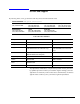
Specifications Specifications Specifications are performance standards or limits against which the detectors are tested. Table 1 Specifications Frequency Range: 10 MHz to 18 GHz Note: RF may leak through the output connector below 1 GHz. It can be reduced, if objectionable, with a suitable low pass filter. Frequency Response: 1, 2, 4 Octave flatness: ±0.2 dB over any octave 10 MHz to 8 GHz Broadband flatness: ±0.3 dB 10 MHz to 12.4 GHz ±0.5 dB 10 MHz to 15 GHz ±0.
Operating Information Operating Information The crystal detector can be used as a demodulator to obtain a pulse envelope which can then be observed on an oscilloscope. It can also be used as a general purpose detector. CAUTION • Static discharge can damage the detector element. A 100 pF capacitor (1.2 m [4 ft] of coax cable) charged to 14 volts stores .1 erg, the maximum pulse rating of the detector element.
Operating Information Operator’s Checks Peak Power Measurement The procedure for peak power measurement involves calibration of an oscilloscope which, in turn, is used to calibrate a CW generator. The output of the calibrated CW generator is measured with a power meter and thereby the peak power of a pulse is measured. Refer to Figure 1 for the equipment setup in the steps referenced below. 1. Measure the output amplitude resulting from the pulse. a. Connect equipment as shown in Figure 1, step A. b.
Operating Information Reflectometer Application For information about reflectometer systems and measurements refer to Agilent Technologies Application Note Index. Copies are available upon request. Harmony Frequency Comparison Measurement Application The detector can be used as a mixer in harmonic-frequency comparison measurements. Refer to Agilent Technologies Application Note Index for further information.
Performance Tests Performance Tests Methods for testing detector specifications are given below. Refer to the manuals of the equipment involved for specific operating instructions. NOTE Multiple mismatch errors caused by attenuator SWR, power meter SWR, and detector SWR should be taken into account, as well as the accuracy of the indicator used to measure the detector’s output. Frequency Response Test 1.
Service Instructions Service Instructions Repair and Replacement Repair and replacement information for the 8472B crystal detector are given below. For additional maintenance information, refer to “Service and Support” on page v for the nearest Agilent Technologies Sales and Service office. The detectors have no internal adjustments. Replaceable Parts Part numbers for replaceable parts are given in Table 2.
Service Instructions CAUTION • • • Do not rotate the detector element while inserting or removing as damage may result. The detector element might be damaged if the detector element is not centered. When inserting the detector element, do not force the large pin end into the center conductor. 3. Remove the old detector element and the polyiron washer. Discard the detector element. 4. Install the RF adapter washer, polyiron ring, axial spacer, and new detector element.
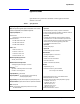
Service Instructions Figure 2 8472B Crystal Detector Assembly Figure 3 8472B Option 100 Crystal Detector Assembly 10 8472B Operating and Service Manual
Service Instructions Table 2 Replaceable Parts Description Part Number 8472B and 8472B, Option 100 Assemblies1 Connector, SMA male 1250-0683 Connector, OSSM female (Option 100) 1250-0924 Spring, compression 1460-0072 Washer, lock internal 2190-0016 Ring, polyiron 5021-0801 Spacer, axial 5021-0802 Washer, RF adapter 5021-0127 Body, crystal mount 08472-2001 Cap, connector 08472-2007 Cap, connector, (Option 100) 08472-20011 Sleeve (Option 100) 08472-20012 Pin and bead assembly include