
User's Manual
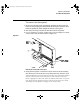
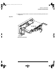
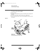
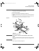
Table Of Contents
- Title page
- Contents
- 1 General Information
- 2 Preparing the Oscilloscope for Use
- 3 Testing Performance
- List of Test Equipment
- To construct the test connector
- To test the 54621D/22D Oscilloscope digital channels
- To verify digital channel threshold accuracy
- To verify voltage measurement accuracy
- To verify bandwidth
- To verify horizontal Dt and 1/Dt accuracy
- To verify trigger sensitivity
- Agilent 54622A/22D/24A Performance Test Record
- Agilent 54621A/21D Performance Test Record
- 4 Calibrating and Adjusting
- 5 Troubleshooting
- 6 Replacing Assemblies
- 7 Replaceable Parts
- Declaration of Conformity
- Notices
6-13
Replacing Assemblies
To remove the power supply
5
Use a flat-blade screwdriver to gently unhook the latch that holds the
white power-actuator shaft to the power switch, then disconnect the
shaft from the power switch. After you disconnect the shaft, make sure
you position it in the recess along the side of the display bracket.
Figure 6-10
Unhooking the power switch shaft
Gently apply outward
pressure at this corner
of the slot
service.book Page 13 Wednesday, December 18, 2002 8:35 AM