service.book Page i Wednesday, December 18, 2002 8:35 AM Service Guide Publication Number 54622-97037 December 2002 For Safety Information, Warranties, and Regulatory information, see the pages at the end of this book.
service.book Page ii Wednesday, December 18, 2002 8:35 AM The Oscilloscope At a Glance Choose from a variety of oscilloscopes for capturing long, non-repeating signals with 200 MSa/s sample rate and 2 MBytes of MegaZoom deep memory per channel.
service.book Page iii Wednesday, December 18, 2002 8:35 AM In This Book This book provides the service information for the Agilent 54621A/22A/24A Oscilloscope and the Agilent 54621D/22D Mixed-Signal Oscilloscope. This manual is divided into these chapters: Chapter 1 provides general information and specifications. Chapter 2 shows you how to prepare the oscilloscope for use. Chapter 3 gives performance tests. Chapter 4 covers calibration and adjustment procedures.
service.
service.
service.
service.book Page 2 Wednesday, December 18, 2002 8:35 AM General Information This chapter lists general information for the Agilent 54620-series Oscilloscopes. It also includes performance characteristics and specifications for the oscilloscopes.
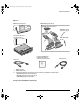
service.book Page 3 Wednesday, December 18, 2002 8:35 AM General Information To inspect package contents ❏ Inspect the shipping container for damage. If your shipping container appears to be damaged, keep the shipping container or cushioning material until you have inspected the contents of the shipment for completeness and have checked the oscilloscope mechanically and electrically.
service.book Page 4 Wednesday, December 18, 2002 8:35 AM General Information • Agilent IntuiLink Data Capture (for 54622A, 22D, or 24A) IntuiLink Data Capture is a standalone program for downloading waveform data from the oscilloscopes to your PC via GPIB or RS-232 interface. It provides the capability to transfer deep memory data out of the oscilloscope, allowing up to 4MB (scope channels) and 8MB (logic channels).
service.
service.book Page 6 Wednesday, December 18, 2002 8:35 AM General Information To inspect options and accessories ❏ Verify that you received the options and accessories you ordered and that none were damaged. If anything is missing, contact your nearest Agilent Sales Office. If the shipment was damaged, or the cushioning materials show signs of stress, notify the carrier and your Agilent Sales Office.
service.book Page 7 Wednesday, December 18, 2002 8:35 AM General Information Table 1-2 Accessories available Model Description 01650-61607 16:16 logic cable and terminator (for use with 54621D/22D) 54620-68701 16:2 x 8 logic input probe assembly (shipped standard with 54621D/22D) 1146A 100 kHz current probe, ac/dc 1183A Testmobile scope cart 1185A Carrying case 1186A Rackmount kit 10070C 1:1 passive probe with ID 10072A Fine-pitch probe kit 10073C 10:1 500 MHz probe with ID 10075A 0.
service.book Page 8 Wednesday, December 18, 2002 8:35 AM General Information Table 1-3. Power Cords Plug Type Cable Part Number Plug Type Cable Part Number Opt 900 (U.K.) 8120-1703 Opt 918 (Japan) 8120-4754 Opt 901 (Australia) 8120-0696 Opt 919 (Israel) 8120-6799 Opt 902 (Europe) 8120-1692 Opt 920 (Argentina) 8120-6871 Opt 903 (U.S.A.
service.book Page 9 Wednesday, December 18, 2002 8:35 AM General Information Acquisition: Analog Channels Performance Characteristics * Denotes Warranted Specifications, all others are typical. Specifications are valid after a 30-minute warm-up period and ±10 °C from firmware calibration temperature.
service.book Page 10 Wednesday, December 18, 2002 8:35 AM General Information Vertical System: Analog Channels * Denotes Warranted Specifications, all others are typical. Specifications are valid after a 30-minute warm-up period and ±10 °C from firmware calibration temperature. Vertical System: Analog Channels Analog channels Bandwidth (-3dB)* ac coupled Calculated rise time (= 0.
service.book Page 11 Wednesday, December 18, 2002 8:35 AM General Information Vertical System: Analog Channels (continued) * Denotes Warranted Specifications, all others are typical. Specifications are valid after a 30-minute warm-up period and ±10 °C from firmware calibration temperature.
service.book Page 12 Wednesday, December 18, 2002 8:35 AM General Information Horizontal * Denotes Warranted Specifications, all others are typical. Specifications are valid after a 30-minute warm-up period and ±10 °C from firmware calibration temperature.
service.book Page 13 Wednesday, December 18, 2002 8:35 AM General Information Trigger System * Denotes Warranted Specifications, all others are typical. Specifications are valid after a 30-minute warm-up period and ±10 °C from firmware calibration temperature.
service.book Page 14 Wednesday, December 18, 2002 8:35 AM General Information Analog Channel Triggering * Denotes Warranted Specifications, all others are typical. Specifications are valid after a 30-minute warm-up period and ±10 °C from firmware calibration temperature. Analog Channel Triggering Range (Internal) Sensitivity* Coupling ±6 div from center screen Greater of 0.35 div or 2.5 mV AC (~3.
service.book Page 15 Wednesday, December 18, 2002 8:35 AM General Information Display System * Denotes Warranted Specifications, all others are typical. Specifications are valid after a 30-minute warm-up period and ±10 °C from firmware calibration temperature.
service.book Page 16 Wednesday, December 18, 2002 8:35 AM General Information FFT * Denotes Warranted Specifications, all others are typical. Specifications are valid after a 30-minute warm-up period and ±10 °C from firmware calibration temperature.
service.book Page 17 Wednesday, December 18, 2002 8:35 AM General Information General Characteristics * Denotes Warranted Specifications, all others are typical. Specifications are valid after a 30-minute warm-up period and ±10 °C from firmware calibration temperature. General Characteristics Physical: Size Weight Calibrator Output Trigger Out Printer Power Kensington lock 32.26 cm wide x 17.27 cm high x 31.75 cm deep (without handle) 6.35 kgs (14 lbs) Frequency ~1.
service.
service.book Page 2 Wednesday, December 18, 2002 8:35 AM Preparing the Oscilloscope for Use To prepare your oscilloscope for use, you need to do the following tasks. After you have completed them, you will be ready to use the oscilloscope.
service.book Page 3 Wednesday, December 18, 2002 8:35 AM Setting up the Oscilloscope After you have done a few basic tasks, you will connect probes to the oscilloscope. The number of probes, and the type of probes that you will use depends on the oscilloscope model that you have. • When using the Agilent 54621A and 54622A 2-channel Oscilloscopes, and the Agilent 54624A 4-channel Oscilloscope, you will connect and use analog probes to examine analog signals.
service.book Page 4 Wednesday, December 18, 2002 8:35 AM Preparing the Oscilloscope for Use To adjust the handle To adjust the handle 1 Grasp the handle pivot points on each side of the instrument and pull the pivot out until it stops. Agilent 54622D MIXED SIGNAL OSCILLOSCOPE CHANNEL Time/Div Select 1s 0 5 ns 15 INPUTS 2 Without releasing the pivots, swivel the handle to the desired position. Then release the pivots. Continue pivoting the handle until it clicks into a set position.
service.book Page 5 Wednesday, December 18, 2002 8:35 AM Preparing the Oscilloscope for Use To power-on the oscilloscope To power-on the oscilloscope 1 Connect the power cord to the rear of the oscilloscope, then to a suitable ac voltage source. The oscilloscope power supply automatically adjusts for input line voltages in the range 100 to 240 VAC. Therefore, you do not need to adjust the input line voltage setting. The line cord provided is matched to the country of origin.
service.book Page 6 Wednesday, December 18, 2002 8:35 AM Preparing the Oscilloscope for Use To adjust the display intensity To adjust the display intensity The Intensity control is at the lower left corner of the front panel. • To decrease display intensity, rotate the Intensity control counterclockwise. • To increase display intensity, rotate the Intensity control clockwise.
service.book Page 7 Wednesday, December 18, 2002 8:35 AM Preparing the Oscilloscope for Use To connect the oscilloscope probes To connect the oscilloscope probes 1 Connect the Agilent 10074C 1.5-meter, 10:1 oscilloscope probe to the analog channel 1 or 2 BNC connector input on the oscilloscope, or channel 1 through channel 4 on the 54624A.
service.book Page 8 Wednesday, December 18, 2002 8:35 AM Preparing the Oscilloscope for Use To use the digital probes (mixed-signal oscilloscope only) To use the digital probes (mixed-signal oscilloscope only) 1 If you feel it’s necessary, turn off the power supply to the circuit under test. Off Turning off power to the circuit under test would only prevent damage that might occur if you accidentally short two lines together while connecting probes.
service.book Page 9 Wednesday, December 18, 2002 8:35 AM Preparing the Oscilloscope for Use To use the digital probes (mixed-signal oscilloscope only) 3 Connect a grabber to one of the probe leads. Be sure to connect the ground lead. (Other probe leads are omitted from the figure for clarity.) Grabber 4 Connect the grabber to a node in the circuit you want to test.
service.book Page 10 Wednesday, December 18, 2002 8:35 AM Preparing the Oscilloscope for Use To use the digital probes (mixed-signal oscilloscope only) 5 For high-speed signals, connect a ground lead to the probe lead, connect a grabber to the ground lead, and attach the grabber to ground in the circuit under test. Signal Lead Ground Lead Grabber 6 Connect the ground lead on each set of channels, using a probe grabber.
service.book Page 11 Wednesday, December 18, 2002 8:35 AM Preparing the Oscilloscope for Use To use the digital probes (mixed-signal oscilloscope only) 7 Repeat steps 3 through 6 until you have connected all points of interest. Signals Ground 8 If you need to remove a probe lead from the cable, insert a paper clip or other small pointed object into the side of the cable assembly, and push to release the latch while pulling out the probe lead. Replacement parts are available.
service.book Page 12 Wednesday, December 18, 2002 8:35 AM Preparing the Oscilloscope for Use To connect a printer To connect a printer The oscilloscope connects to a parallel printer through the Parallel output connector on the rear of the oscilloscope. You will need a parallel printer cable to connect to the printer. 1 Attach the 25-pin small “D” connector to the Parallel output connector on the rear of the oscilloscope. Tighten the thumbscrews on the cable connector to secure the cable.
service.book Page 13 Wednesday, December 18, 2002 8:35 AM Preparing the Oscilloscope for Use To verify basic oscilloscope operation To verify basic oscilloscope operation 1 Connect an oscilloscope probe to channel 1. 2 Attach the probe to the Probe Comp output on the lower-right side of the front panel of the oscilloscope. Use a probe retractable hook tip so you do not need to hold the probe. 3 Press the Save/Recall key on the front panel, then press the Default Setup softkey under the display.
service.book Page 14 Wednesday, December 18, 2002 8:35 AM Getting started using the oscilloscope interface When the oscilloscope is first turned on, it performs a self-test, then momentarily shows a startup screen as shown below. This menu is only accessible when the oscilloscope first starts up.
service.book Page 15 Wednesday, December 18, 2002 8:35 AM Preparing the Oscilloscope for Use To verify basic oscilloscope operation • Press the Getting Started softkey to view the symbols used in the oscilloscope softkey menus. Use the Entry knob labeled to adjust the parameter. Press the softkey to display a pop up with a list of choices. Repeatedly press the softkey until your choice is selected. ✓ Use the Entry knob labeled or press the softkey to adjust the parameter.
service.book Page 16 Wednesday, December 18, 2002 8:35 AM Using Quick Help The oscilloscope has a Quick Help system that provides user help for each front-panel key and softkey on the oscilloscope. To view Quick Help information: 1 Press and hold down the key for which you would like to view help. 2 Release the key after reading the message. Releasing the key returns the oscilloscope to the previous state.
service.book Page 17 Wednesday, December 18, 2002 8:35 AM Preparing the Oscilloscope for Use Selecting a language for Quick Help after you have been operating the oscilloscope Selecting a language for Quick Help after you have been operating the oscilloscope 1 Press the Utility key, then press the Language softkey to display the Language menu. 2 Press the Language softkey until the desired language in the list selected.
service.book Page 18 Wednesday, December 18, 2002 8:35 AM Preparing the Oscilloscope for Use Loading a language from floppy disk Loading a language from floppy disk Language files can be downloaded from www.agilent.com/find/5462xsw or call an Agilent center and request a language disk for your instrument. 1 Insert the floppy disk with a language file into the floppy disk drive on the oscilloscope. 2 Press the Utility key, then press the Language softkey to display the Language menu.
service.book Page 19 Wednesday, December 18, 2002 8:35 AM Cleaning the oscilloscope 1 Disconnect power from the instrument. CAUTION Avoid Damage to Sensitive Electronic Components! Do not use too much liquid in cleaning the oscilloscope. Water can enter the front-panel keyboard, control knobs, or floppy disk damaging sensitive electronic components. 2 Clean the oscilloscope with a soft cloth dampened with a mild soap and water solution.
service.
service.book Page 2 Wednesday, December 18, 2002 8:35 AM Testing Performance This chapter explains how to verify correct oscilloscope operation and perform tests to ensure that the oscilloscope meets the performance specifications. To completely test and troubleshoot the mixed-signal oscilloscope, you will create and use a test connector accessory, as described in this chapter.
service.book Page 3 Wednesday, December 18, 2002 8:35 AM Testing Performance List of Test Equipment List of Test Equipment Below is a list of test and equipment and accessories required to perform the performance test verification procedures.
service.book Page 4 Wednesday, December 18, 2002 8:35 AM Testing Performance To construct the test connector To construct the test connector The Agilent 54621D/22D Mixed-Signal Oscilloscope has digital channels that you will need to connect to test equipment during testing. To easily connect the digital channels, you will construct a test connector only if the 01660-63801 Test Fixture is not available.
service.book Page 5 Wednesday, December 18, 2002 8:35 AM Testing Performance To test the 54621D/22D Oscilloscope digital channels To test the 54621D/22D Oscilloscope digital channels Only the 54621D/22D Mixed-Signal Oscilloscope has Digital Channels You need to perform these instructions only if you will be testing the digital channels on the Agilent 54621D/22D Mixed-Signal Oscilloscope. The acquisition system testing provides confidence that the acquisition system is functioning correctly.
service.book Page 6 Wednesday, December 18, 2002 8:35 AM Testing Performance To verify digital channel threshold accuracy To verify digital channel threshold accuracy This test verifies the digital channel threshold accuracy specification of the Agilent 54621D/22D Mixed-Signal Oscilloscope. Test Threshold Accuracy only on the 54621D/22D Mixed-Signal Oscilloscope You need to perform these instructions only if you will be testing the Agilent 54621D/22D Mixed-Signal Oscilloscope.
service.book Page 7 Wednesday, December 18, 2002 8:35 AM Testing Performance To verify digital channel threshold accuracy 1 Turn on the test equipment and the oscilloscope. Let them warm up for 30 minutes before starting the test. 2 Set up the oscilloscope calibrator. a Set the oscilloscope calibrator to provide a DC offset voltage at the Channel 1 output. b Use the multimeter to monitor the oscilloscope calibrator DC output voltage.
service.book Page 8 Wednesday, December 18, 2002 8:35 AM Testing Performance To verify digital channel threshold accuracy b Method 2 — Using the Test Fixture Use the Agilent 01660-63801 Performance Verification Test Fixture and the Agilent 01650-61607 cable, BNC Tee, and BNC cable to connect the digital channels D0 - D15 to the oscilloscope calibrator. See figure 3-3.
service.book Page 9 Wednesday, December 18, 2002 8:35 AM Testing Performance To verify digital channel threshold accuracy 7 Press the oscilloscope User softkey, then turn the Entry knob ( ) on the front panel on the oscilloscope to set the threshold test settings as shown in Table 3-3. Table 3-3 Threshold Accuracy Voltage Test Settings Threshold voltage setting DC offset voltage setting (in oscilloscpe User softkey) (on oscilloscope calibrator) Limits +5.00 V +5.250 V ±1 mV dc Lower limit = +4.
service.book Page 10 Wednesday, December 18, 2002 8:35 AM Testing Performance To verify voltage measurement accuracy To verify voltage measurement accuracy This test verifies the voltage measurement accuracy. In this test, you will measure the output of a power supply using dual cursors on the oscilloscope, and compare the results with the multimeter reading. Test limits: ±2.0% of full scale ±1 LSB* • Full scale is defined as 16 mV on the 1 mV/div range.
service.book Page 11 Wednesday, December 18, 2002 8:35 AM Testing Performance To verify voltage measurement accuracy b Set the Volts/Div setting to the value in the first line in Table 3-5. Table 3-5 Settings Used to Verify Voltage Measurement Accuracy Volts/Div Setting Power Supply Setting Test Limits 5 V/Div 35 V 34.04 V to 35.96 V 2 V/Div 14 V 13.616 V to 14.384 V 1 V/Div 7V 6.808 V to 7.192 V 0.5 V/Div 3.5 V 3.404 V to 3.596 V 0.2 V/Div 1.4 V 1.3616 V to 1.4384 V 0.
service.book Page 12 Wednesday, December 18, 2002 8:35 AM Testing Performance To verify voltage measurement accuracy 3 Use the BNC tee and cables to connect the oscilloscope calibrator /power supply to both the oscilloscope and the multimeter. 4 Adjust the output so that the multimeter reading displays the first Volts/div supply setting value in Table 3-5. Wait a few seconds for the measurement to settle.
service.book Page 13 Wednesday, December 18, 2002 8:35 AM Testing Performance To verify bandwidth To verify bandwidth This test verifies bandwidth. In this test you will use an oscilloscope calibrator with a level sinewave output. You will use the peak-to-peak voltage both at 1 MHz and at bandwidth frequency to verify the bandwidth response of the oscilloscope.
service.book Page 14 Wednesday, December 18, 2002 8:35 AM Testing Performance To verify bandwidth 1 Connect the oscilloscope calibrator output through a 50Ω feedthrough to the oscilloscope channel 1 input. 2 Set up the oscilloscope. a Set the time base to 500 ns/div. b Set the Volts/Div for channel 1 to 200 mV/div. c Press the Acquire key, then press the Averaging softkey. d Turn the Entry knob to set # Avgs to 8 averages. 3 4 5 6 Set the calibrator to “Level Sine” and OPR/STBY to “OPR”.
service.book Page 15 Wednesday, December 18, 2002 8:35 AM Testing Performance To verify horizontal Dt and 1/Dt accuracy To verify horizontal ∆t and 1/∆t accuracy This test verifies the horizontal ∆t and 1/∆t accuracy. In this test, you will use the oscilloscope to measure the output of a time mark generator. Test limits: ±0.01% of reading ±0.
service.book Page 16 Wednesday, December 18, 2002 8:35 AM Testing Performance To verify horizontal Dt and 1/Dt accuracy 4 Change the calibrator to 1-µs markers. Change the time base to 200 ns/div. Adjust the trigger level to obtain a stable display. 5 Measure the following: Frequency 1 MHz — The test limits are 997.9 kHz to 1.002 MHz. Period 1 µs — The test limits are 997.9 ns to 1.002 µs. If the measurements are not within the test limits, see the “Troubleshooting” chapter. Then return here.
service.book Page 17 Wednesday, December 18, 2002 8:35 AM Testing Performance To verify trigger sensitivity To verify trigger sensitivity This test verifies the trigger sensitivity. In this test, you will apply 25 MHz to the oscilloscope. You will then decrease the amplitude of the signal to the specified levels, and check to see if the oscilloscope is still triggered. You will then repeat the process at the upper bandwidth limit.
service.book Page 18 Wednesday, December 18, 2002 8:35 AM Testing Performance To verify trigger sensitivity Test Internal Trigger Sensitivity 1 Press the Save/Recall key, then press the Default Setup softkey. 2 Connect the calibrator to channel 1 using a 50Ω feedthrough at the oscilloscope input. 3 Verify the trigger sensitivity at 25 MHz and 0.35 divisions. a Set the output of the calibrator to 25 MHz, and set the amplitude to about b c d e f 100 mVp-p. Press the Autoscale key.
service.book Page 19 Wednesday, December 18, 2002 8:35 AM Testing Performance To verify trigger sensitivity Test External Trigger Sensitivity Verify the external trigger sensitivity at these settings: 100 MHz (54622A/22D/24A), <150 mVp-p 60 MHz (54621A/21D), <150 mVp-p 25 MHz (All models), <75 mVp-p 1 Use the power splitter to connect the calibrator to both the channel 1 input and the external trigger input.
service.book Page 20 Wednesday, December 18, 2002 8:35 AM Agilent 54622A/22D/24A Performance Test Record Agilent 54622A/54622D/54624A Serial No. ______________________________________ Test Interval ____________________________________ Recommended Next Testing ________________________ Test by _____________________________ Work Order No. ______________________ Temperature ____________ Threshold Accuracy Test (100 mV + 3% of threshold setting) Limits 4.750 V 5.250 V -5.250 V -4.
service.book Page 21 Wednesday, December 18, 2002 8:35 AM Agilent 54621A/21D Performance Test Record Agilent 54621A/54621D Serial No. ______________________________________ Test Interval ____________________________________ Recommended Next Testing ________________________ Test by _____________________________ Work Order No. ______________________ Temperature ____________ Threshold Accuracy Test (100 mV + 3% of threshold setting) Limits 4.750 V 5.250 V -5.250 V -4.
service.
service.book Page 2 Wednesday, December 18, 2002 8:35 AM Calibrating and Adjusting This chapter explains how to adjust the oscilloscope for optimum operating performance. You should perform the hardware adjustments and self-calibration according to the following recommendations. • Perform hardware adjustments every 12 months or after 2,000 hours of operation.
service.book Page 3 Wednesday, December 18, 2002 8:35 AM Calibrating and Adjusting WARNING HAZARDOUS VOLTAGES ! Read the safety summary at the back of this book before proceeding. Maintenance is performed with power supplied to the oscilloscope and with the protective covers removed. Only trained service personnel who are aware of the hazards involved should perform the maintenance. Whenever possible, perform the procedures with the power cord removed from the oscilloscope.
service.book Page 4 Wednesday, December 18, 2002 8:35 AM Calibrating and Adjusting To adjust the power supply To adjust the power supply The oscilloscope power supply has both a +3.3 V adjustment, and a +5.1 V / -5.2 V balance adjustment. Other oscilloscope voltages are based on the +3.3 V adjustment. In this procedure, you will use a digital multimeter to measure the +3.3 V and +5.1 V / -5.2 V test points, and adjust the power supplies to be within tolerance, if necessary.
service.book Page 5 Wednesday, December 18, 2002 8:35 AM Calibrating and Adjusting To adjust the power supply 2 Locate the power supply voltages at E204, E205, E207, and E208 on the system board. The power supply voltages are not labeled on the system board. See Figure 4-1 for the locations.
service.book Page 6 Wednesday, December 18, 2002 8:35 AM Calibrating and Adjusting To adjust the power supply 4 If the +5.1 V measurement is out of tolerance, adjust the +5.1 V / -5.2 V balance adjustment on the power supply. See Figure 4-2. 5 If the -5.2 V measurement is out of tolerance, adjust the +5.1 V / -5.2 V balance adjustment on the power supply. See Figure 4-2. The +15.75 V supply is not adjustable, and is dependent upon the +5.1 V supply. Figure 4-2 +3.3V Adjustment +5.1 / -5.
service.book Page 7 Wednesday, December 18, 2002 8:35 AM Calibrating and Adjusting To perform User Cal To perform User Cal Perform self-calibration: • every 6 months or after 1000 hours of operation. • if the ambient temperature is >10 °C from the calibration temperature. • if you want to maximize the measurement accuracy. The amount of use, environmental conditions, and experience with other instruments help determine if you need shorter adjustment intervals.
service.book Page 8 Wednesday, December 18, 2002 8:35 AM Calibrating and Adjusting To adjust the oscilloscope display To adjust the oscilloscope display When to Adjust the Oscilloscope Display The oscilloscope display normally does not require adjustment. However, when it is obvious that the display is out of adjustment, use this optional procedure. In this procedure, you will make adjustments using two display patterns.
service.book Page 9 Wednesday, December 18, 2002 8:35 AM Calibrating and Adjusting To adjust the oscilloscope display 5 Adjust H.HOLD (horizontal hold) to center the display horizontally. 6 Adjust FOCUS to achieve the best focus. 7 Adjust V.LIN (vertical linearity) to position all four corners of the half- bright borders equally. 8 Adjust V.SIZE (vertical size) to center the display vertically at the maximum allowable size without losing the half-bright borders. Because V.LIN and V.
service.
service.book Page 2 Wednesday, December 18, 2002 8:35 AM Troubleshooting This chapter begins with suggestions for solving general problems that you may encounter with the oscilloscope. It tells you what to do in these cases: • • • • If there is no trace display If the trace display is unusual or unexpected If you cannot see a channel If you cannot get any response from the oscilloscope Procedures for troubleshooting the oscilloscope follow the problem solving suggestions.
service.book Page 3 Wednesday, December 18, 2002 8:35 AM Solving General Problems with the Oscilloscopes This section describes how to solve general problems that you may encounter while using the 54621A/22A/24A Oscilloscopes and the 54621D/22D Mixed-Signal Oscilloscopes to make measurements. After troubleshooting the oscilloscope, if you need to replace parts, refer to the “Replaceable Parts” chapter.
service.book Page 4 Wednesday, December 18, 2002 8:35 AM Troubleshooting If the trace display is unusual or unexpected If the trace display is unusual or unexpected ❏ Check that the Horizontal time/division setting is correct for the expected frequency range of the input signals. ❏ The sampling speed of the oscilloscope depends on the time/division setting.
service.book Page 5 Wednesday, December 18, 2002 8:35 AM Troubleshooting If you cannot see a channel If you cannot see a channel ❏ Check that the oscilloscope probe cable is securely connected to the input connector. ❏ Check that the oscilloscope probe lead wires are securely inserted into the connector assembly and that the probe clips make good contact with the probe lead wires. ❏ Check that the probe clips are securely connected to points in the circuit under test.
service.book Page 6 Wednesday, December 18, 2002 8:35 AM Troubleshooting the Oscilloscope The service policy for the 54621A/22A/24A Oscilloscopes and the 54621D/22D Mixed-Signal Oscilloscopes is instrument replacement. Please call (877) 447-7278 to return the defective instrument, and Agilent Technologies will expedite a refurbished instrument to you under the Agilent Express Exchange program.
service.book Page 7 Wednesday, December 18, 2002 8:35 AM Troubleshooting To construct your own dummy load To construct your own dummy load 1 Obtain a connector that is compatible with the connector J3 on the Low Voltage Power Supply. 2 Connect load resistors to the connector as follows: Connector +5.1 V -5.2 V +15.75 V +3.3 V Load (Amps) 4.4 A 1.6 A 1.2 A 4A Resistor 1.2 Ω 3.25 Ω 13.1 Ω 0.
service.book Page 8 Wednesday, December 18, 2002 8:35 AM Troubleshooting To check out the oscilloscope To check out the oscilloscope 1 Is an interface module connected to the rear panel of the oscilloscope? If the answer is yes, follow these steps. Otherwise, go to step 2. a Turn off the oscilloscope. b Remove the interface module. c Turn on the oscilloscope, then check for the failing symptom. d If the failing symptom is not present, replace the interface module.
service.book Page 9 Wednesday, December 18, 2002 8:35 AM Troubleshooting To check out the oscilloscope 5 Disconnect the display ribbon cable from the system board. Then check the signals on the system board listed in Table 5-2. Table 5-2 Display Signals on the System Board – All Oscilloscopes Signal Name Frequency Pulse Width Voltage J900 Pin 14 Hsync 19.72 kHz 3.0 ms 4.5 Vp-p J900 Pin 13 Vsync 60.00 Hz 253.5 ms 4.5 Vp-p If the signals are good, replace the display assembly.
service.book Page 10 Wednesday, December 18, 2002 8:35 AM Troubleshooting To check out the oscilloscope 8 Is the fan running? The low voltage power supply has a thermal cut-out circuit. If the fan is defective, the low voltage power supply will shut down when it gets too hot for safe operation. If the fan is running, perform the internal self-tests. Go to “To run the internal self-tests” on page 5-13. If the fan is not running, it may be defective.
service.book Page 11 Wednesday, December 18, 2002 8:35 AM Troubleshooting To check the Low Voltage Power Supply To check the Low Voltage Power Supply 1 Disconnect the power cord from the oscilloscope. Then remove the oscilloscope cover and set the oscilloscope on its side. CAUTION USE AN EXTERNAL FAN TO AVOID OVERHEATING COMPONENTS ! If you operate the oscilloscope with the cabinet removed, you must use an external fan to blow air across the system board.
service.book Page 12 Wednesday, December 18, 2002 8:35 AM Troubleshooting To check the Low Voltage Power Supply Table 5-4 Low Voltage Power Supply Tolerances Supply Voltage Tolerance +5.1 V ±153 mV (+4.947 V to +5.253 V) -5.2 V ±156 mV (-5.04 V to -5.36 V) +15.75 V +1.260 V, -787 mV (+14.963 V to +17.010 V) +3.3 V ±100 mV (+3.20 V to +3.40 V) 4 If the +5.1 V measurement is out of tolerance, adjust the +5.1 V adjustment on the power supply. 5 If the -5.
service.book Page 13 Wednesday, December 18, 2002 8:35 AM Troubleshooting To run the internal self-tests To run the internal self-tests Self Test performs a series of internal procedures to verify that the oscilloscope and any attached module are operating properly.
service.
service.book Page 2 Wednesday, December 18, 2002 8:35 AM Replacing Assemblies This chapter describes how to remove assemblies from the oscilloscope. After you have removed an assembly, to install the replacement assembly, follow the instructions in reverse order.
service.book Page 3 Wednesday, December 18, 2002 8:35 AM Replacing Assemblies WARNING HAZARDOUS VOLTAGES ! Read the safety summary at the back of this book before proceeding. Maintenance is performed with power supplied to the oscilloscope and with the protective covers removed. Only trained service personnel who are aware of the hazards involved should perform the maintenance. Whenever possible, perform the procedures with the power cord removed from the oscilloscope.
service.book Page 4 Wednesday, December 18, 2002 8:35 AM Replacing Assemblies To remove the cabinet To remove the cabinet Turn off the oscilloscope and disconnect the power cable. Rotate the handle up as shown below. If a module is installed, remove it from the oscilloscope. Using the T20 TORX driver, remove the two screws from the rear of the cabinet. 5 Using your thumbs, gently push on the rear-panel connectors to slide the oscilloscope out of the cabinet.
service.book Page 5 Wednesday, December 18, 2002 8:35 AM Replacing Assemblies To remove the fan To remove the fan 1 Disconnect the fan cable from the power supply board. 2 Using the T20 TORX driver, remove the three screws that hold the fan to the deck.
service.book Page 6 Wednesday, December 18, 2002 8:35 AM Replacing Assemblies To remove the floppy drive To remove the floppy drive 1 Using the T8 TORX driver, loosen the two screws that hold the drive to the deck. 2 Lift the drive away from the system board. 3 Disconnect the ribbon cable from the connector on the rear of the drive.
service.book Page 7 Wednesday, December 18, 2002 8:35 AM Replacing Assemblies To remove the front panel To remove the front panel 1 Remove the intensity knob and shaft by grasping the knob with one hand and the grasping the shaft behind the front panel with the other hand and pulling the shaft straight out from the front panel. 2 Disconnect the keyboard ribbon cable W2 from the keyboard. 3 Use a screwdriver to release retainer tab A, and your finger to release retainer tab B.
service.book Page 8 Wednesday, December 18, 2002 8:35 AM Replacing Assemblies To remove the display To remove the display 1 Remove the front panel from the oscilloscope. 2 Disconnect the ribbon cable from the display board. 3 Using the T20 TORX driver, remove the four screws that hold the display to the deck. Set these screws aside.
service.book Page 9 Wednesday, December 18, 2002 8:35 AM Replacing Assemblies To remove the display 4 Use a flat-blade screwdriver to gently unhook the latch that holds the white power-actuator shaft to the power switch, then disconnect the shaft from the power switch. After you disconnect the shaft, make sure you position it in the recess along the side of the display bracket.
service.book Page 10 Wednesday, December 18, 2002 8:35 AM Replacing Assemblies To remove the system board To remove the system board 1 Remove the floppy drive. 2 Using the T10 TORX driver, remove the six screws that hold the system board to the deck. 3 Remove the two hex nuts and washers from the rear BNCs using the 9/16-inch socket driver. The 54621D , 54622D, and 54624A have two rear BNCs, the 54621A and 54622A have one rear BNC.
service.book Page 11 Wednesday, December 18, 2002 8:35 AM Replacing Assemblies To remove the system board 7 Lift the back of the board to clear the main deck and then pull the board straight out.
service.book Page 12 Wednesday, December 18, 2002 8:35 AM Replacing Assemblies To remove the power supply To remove the power supply 1 Remove the fan. 2 Disconnect the ground wire (green wire with the yellow stripe) from the deck. 3 Disconnect the ribbon cable from the power supply board. 4 Remove the printer power connector by sliding the connector out of the chassis.
service.book Page 13 Wednesday, December 18, 2002 8:35 AM Replacing Assemblies To remove the power supply 5 Use a flat-blade screwdriver to gently unhook the latch that holds the white power-actuator shaft to the power switch, then disconnect the shaft from the power switch. After you disconnect the shaft, make sure you position it in the recess along the side of the display bracket.
service.book Page 14 Wednesday, December 18, 2002 8:35 AM Replacing Assemblies To remove the power supply 6 Using the T20 TORX driver, remove the screw holding the power supply board to the deck. Figure 6-11 Removing the power supply 7 Slide the power supply board toward the front panel about 1/2 inch. Slip the power supply board keyhole slots off of the pins on the deck.
service.book Page 15 Wednesday, December 18, 2002 8:35 AM Replacing Assemblies To remove the keyboard assembly To remove the keyboard assembly 1 Remove the front panel. 2 Remove all of the knobs by pulling them straight out. 3 Using the T10 TORX driver, remove the four screws from the keyboard shield. 4 Lift the ribbon cable end of the small keyboard and simultaneously slide the small keyboard toward the main keyboard to remove.
service.book Page 16 Wednesday, December 18, 2002 8:35 AM Replacing Assemblies To remove the handle To remove the handle • Rotate the handle downward until it just passes the last detente position; this is about 1/2 inch before the handle touches the bottom of the oscilloscope. • Pull the sides of the handle out of the cabinet.
service.
service.book Page 2 Wednesday, December 18, 2002 8:35 AM Replaceable Parts This chapter describes how to order replaceable assemblies and parts for the Agilent 54621A/22A/24A Oscilloscope and Agilent 54621D/22D Mixed-Signal Oscilloscope. Diagrams and parts lists are included for assemblies and hardware that you can order. Before working on the oscilloscope, read the safety summary at the back of this book.
service.book Page 3 Wednesday, December 18, 2002 8:35 AM Replaceable Parts To order a replacement part To order a replacement part • To order a part in the material list, quote the Agilent Technologies part number, indicate the quantity desired, and address the order to your nearest Agilent Technologies Sales Office.
service.
service.
service.
service.book Page 7 Wednesday, December 18, 2002 8:35 AM Replaceable Parts To order a replacement part Reference Designator Agilent Part Number Qty MP25 54622-63403 See Descr Attenuator lid (54621A/21D/22A/22D - 1 each) (54624A - 2 each) W1 W2 W3 W4 54630-61601 54710-61603 54801-61625 54630-61602 1 1 1 1 W5 W5 W5 W5 W5 8120-1703 8120-0696 8120-1692 8120-1521 8120-2296 Power cord option 900, United Kingdom Power cord option 901, Australia Power cord option 902, Europe Power cord option 903, U.S.
service.book Page i Wednesday, December 18, 2002 8:35 AM DECLARATION OF CONFORMITY According to ISO/IEC Guide 22 and CEN/CENELEC EN 45014 Manufacturer’s Name: Manufacturer’s Address: Agilent Technologies, Inc. Garden of the Gods Road Colorado Springs, Colorado 80907 U.S.A.
service.book Page ii Wednesday, December 18, 2002 8:35 AM Product Regulations EMC Performance Criteria IEC 61326-1:1997+A1:1998 / EN 61326-1:1997+A1:1998 CISPR 11:1990 / EN 55011:1991 IEC 61000-4-2:1995+A1:1998 / EN 61000-4-2:1995 IEC 61000-4-3:1995 / EN 61000-4-3:1995 IEC 61000-4-4:1995 / EN 61000-4-4:1995 IEC 61000-4-6:1996 / EN 61000-4-6:1996 Canada: ICES-001:1998 Safety B B B A, B (1) IEC 61010-1:1990+A1:1992+A2:1995 / EN 61010-1:1993+A2:1995 Canada: CSA C22.2 No. 1010.
service.book Page 3 Wednesday, December 18, 2002 8:35 AM Safety Notices • Whenever it is likely that the ground protection is impaired, you must make the instrument inoperative and secure it against any unintended operation. This apparatus has been designed and tested in accordance with IEC Publication 1010, Safety Requirements for Measuring Apparatus, and has been supplied in a safe condition. This is a Safety Class I instrument (provided with terminal for protective earthing).
service.book Page 4 Wednesday, December 18, 2002 8:35 AM Notices © Agilent Technologies, Inc. 20002002 No part of this manual may be reproduced in any form or by any means (including electronic storage and retrieval or translation into a foreign language) without prior agreement and written consent from Agilent Technologies, Inc. as governed by United States and international copyright laws.