
User's Manual

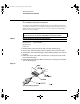
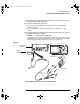
Table Of Contents
- Title page
- Contents
- 1 General Information
- 2 Preparing the Oscilloscope for Use
- 3 Testing Performance
- List of Test Equipment
- To construct the test connector
- To test the 54621D/22D Oscilloscope digital channels
- To verify digital channel threshold accuracy
- To verify voltage measurement accuracy
- To verify bandwidth
- To verify horizontal Dt and 1/Dt accuracy
- To verify trigger sensitivity
- Agilent 54622A/22D/24A Performance Test Record
- Agilent 54621A/21D Performance Test Record
- 4 Calibrating and Adjusting
- 5 Troubleshooting
- 6 Replacing Assemblies
- 7 Replaceable Parts
- Declaration of Conformity
- Notices
3-8
Testing Performance
To verify digital channel threshold accuracy
b Method 2 — Using the Test Fixture
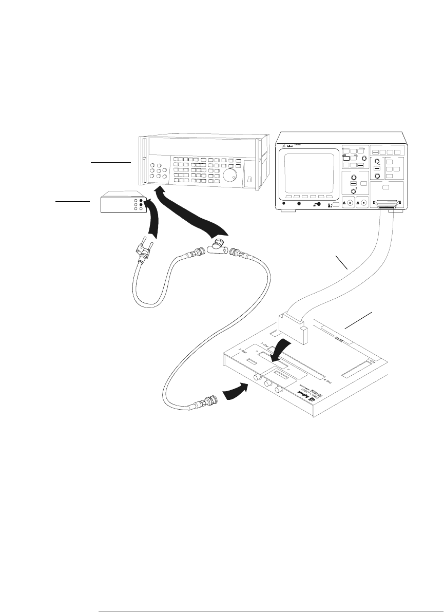
Use the Agilent 01660-63801 Performance Verification Test Fixture and the
Agilent 01650-61607 cable, BNC Tee, and BNC cable to connect the digital
channels D0 - D15 to the oscilloscope calibrator. See figure 3-3.
Figure 3-3
Setting Up Equipment and Test Fixture for the Threshold Test
4 Use a BNC-banana cable to connect the multimeter to the other side of
the BNC Tee.
5 Connect the BNC Tee to the Channel 1 output of the calibrator as shown
in figure 3-2 and figure 3-3.
6 On the oscilloscope, press the D7 Thru D0 key, then press the Threshold
softkey.
Measu re time
Save/Recall
Entry
Mixed Signal Oscilloscop e
16 CHANNEL 500 MSa/s
STORAG E
TRIGGER
HORIZONTAL
CHANNEL
INPUTS
Line
Time/Div
Select
Trigger out
!
Delay
Po si ti on
Ex t tr igg er in
!
!
thresh2.cdr
HP 34401A
01660-63801
Test Fixture
BNC-Banana
cable
01650-61607
Cable
Oscilloscope
Calibrator
Digital
Multimeter
service.book Page 8 Wednesday, December 18, 2002 8:35 AM