
User's Manual
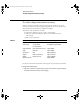
Table Of Contents
- Title page
- Contents
- 1 General Information
- 2 Preparing the Oscilloscope for Use
- 3 Testing Performance
- List of Test Equipment
- To construct the test connector
- To test the 54621D/22D Oscilloscope digital channels
- To verify digital channel threshold accuracy
- To verify voltage measurement accuracy
- To verify bandwidth
- To verify horizontal Dt and 1/Dt accuracy
- To verify trigger sensitivity
- Agilent 54622A/22D/24A Performance Test Record
- Agilent 54621A/21D Performance Test Record
- 4 Calibrating and Adjusting
- 5 Troubleshooting
- 6 Replacing Assemblies
- 7 Replaceable Parts
- Declaration of Conformity
- Notices

3-17
Testing Performance
To verify trigger sensitivity
To verify trigger sensitivity
This test verifies the trigger sensitivity. In this test, you will apply 25 MHz to the
oscilloscope. You will then decrease the amplitude of the signal to the specified
levels, and check to see if the oscilloscope is still triggered. You will then repeat
the process at the upper bandwidth limit.
Test limits for the Internal trigger:
1 mV to 5 V/div (dc to max bandwidth): greater of 0.35 div or 2.5 mV
p-p
Test limits for the External trigger:
dc to 25 MHz: <75 mV
p-p
25 MHz to max bandwidth: <150 mV
p-p
Table 3-9 Equipment Required to Verify Trigger Sensitivity
Equipment Critical Specifications Recommended Model/Part
Oscilloscope Calibrator 25-MHz, 60-MHz and 100-MHz sine
waves
Fluke 5820A
Power splitter Outputs differ < 0.15 dB Agilent 11667B
Cable * BNC, Qty 3 Agilent 10503A
Adapter N (m) to BNC (f), Qty 3 Agilent 1250-0780
Feedthrough 50
Ω, BNC connectors (m) and (f) Agilent 11048C (2 required)
* The oscilloscope calibrator is supplied with 2 or more coaxial cables N (m), BNC (m),
1 meter long, Fluke P/N 686318.
service.book Page 17 Wednesday, December 18, 2002 8:35 AM