Agilent 86100B Wide-Bandwidth Oscilloscope Getting Started
Notices © Agilent Technologies, Inc. 2000-2002 Warranty Safety Notices No part of this manual may be reproduced in any form or by any means (including electronic storage and retrieval or translation into a foreign language) without prior agreement and written consent from Agilent Technologies, Inc. as governed by United States and international copyright lays. The material contained in this document is provided “as is,” and is subject to being changed, without notice, in future editions.
Contents 1 Setting Up the Infiniium DCA Step 1. Inspect the Shipment 1–5 Step 2. Install any Modules 1–9 Step 3. Consider Environmental Specifications 1–10 Step 4. Connect the Keyboard and Mouse (Optional) 1–11 Step 5. Connect the Line Cord 1–12 Step 6. Turn on the line power 1–15 Step 7. Set the time and date 1–17 Step 8. Connect a Printer 1–18 Step 9. Calibrate the Touch Screen 1–22 Step 10. Configure the Instrument on a LAN 1–23 Step 11. Avoid Costly Repairs 1–24 Step 12.
Contents Hiding the Help 4–8 Printing the Contents of a Topic 4–9 Selecting the Help Language 4–10 5 Regulatory Information Compliance with German Noise Requirements 5–2 Compliance with Canadian EMC Requirements 5–2 Declaration of Conformity - Mainframe 5–3 Declaration of Conformity - Plug-in Modules 5–4 Contents-2
1 Step 1. Inspect the Shipment 1-5 Step 2. Install any Modules 1-9 Step 3. Consider Environmental Specifications 1-10 Step 4. Connect the Keyboard and Mouse (Optional) 1-11 Step 5. Connect the Line Cord 1-12 Step 6. Turn on the line power 1-15 Step 7. Set the time and date 1-17 Step 8. Connect a Printer 1-18 Step 9. Calibrate the Touch Screen 1-22 Step 10. Configure the Instrument on a LAN 1-23 Step 11. Avoid Costly Repairs 1-24 Step 12. Perform a Module Calibration 1-26 Step 13.
Setting Up the Infiniium DCA Setting Up the Infiniium DCA Setting Up the Infiniium DCA This chapter shows you how to properly set up your Infiniium DCA. Follow the setup steps in the order presented. In addition, you will learn how to use proper optical connection cleaning techniques to avoid costly repairs. Lastly, this chapter explains how to return your instrument for service.
Setting Up the Infiniium DCA General Safety Considerations WARNING If this product is not used as specified, the protection provided by the equipment could be impaired. This product must be used in a normal condition (in which all means for protection are intact) only. WARNING No operator serviceable parts inside. Refer servicing to qualified service personnel. To prevent electrical shock do not remove covers. WARNING To prevent electrical shock, disconnect the instrument from mains before cleaning.
Setting Up the Infiniium DCA Instrument Markings Instrument Markings The instruction manual symbol. The product is marked with this warning symbol when it is necessary for the user to refer to the instructions in the manual. The laser radiation symbol. This warning symbol is marked on products which have a laser output. The AC symbol is used to indicate the required nature of the line module input power. The Standby symbol is used to mark the position of the instrument power line switch.
Setting Up the Infiniium DCA Step 1. Inspect the Shipment Step 1. Inspect the Shipment ❒ Inspect the shipping container for damage. ❒ Inspect the instrument. ❒ Verify that you received the options and accessories you ordered.
Setting Up the Infiniium DCA Options and Accessories NOTE Keep the shipping container and cushioning material until you have inspected the contents of the shipment for completeness and have checked the instrument mechanically and electrically. If anything is missing or defective, contact your nearest Agilent Technologies Sales Office. Refer to “Agilent Technologies Service Offices” on page 1-43. If the shipment was damaged, contact the carrier, then contact the nearest Agilent Sales Office.
Setting Up the Infiniium DCA Options and Accessories Table 1-3. Optional Accessories Accessory Description 10086A ECL terminator 11667B Power splitter, dc to 26.5 GHz, APC 3.5 mm 11667C Power splitter, dc to 50 GHz, 2.4 mm 11898A Plug-in module remote/extender 11982A High-speed lightwave receiver 54006A 6 GHz Resistive divider probe kit 54008B 24 ns delay line 54701A 2.5 GHz active probe 83430A 2.
Setting Up the Infiniium DCA Options and Accessories Table 1-5.
Setting Up the Infiniium DCA Step 2. Install any Modules Step 2. Install any Modules Up to two modules can be inserted into the Infiniium DCA. All documentation (including specifications) for plug-in modules is located in the Infiniium DCA’s Help system. To access the Help, touch or click Contents on the Help menu. 1 Slide the module into an available front-panel slot. You can remove or install a module while the instrument is operating. 2 Finger tighten the two knurled screws on the module’s front panel.
Setting Up the Infiniium DCA Step 3. Consider Environmental Specifications Step 3. Consider Environmental Specifications Review the following specifications to ensure that your operating or storage environment is suitable for the instrument. Table 1-6.
Setting Up the Infiniium DCA Step 4. Connect the Keyboard and Mouse (Optional) Step 4. Connect the Keyboard and Mouse (Optional) Connect the standard PC-compatible mouse and keyboard that is supplied with the instrument. NOTE Do not stack other objects on the keyboard; this will cause self-test failures on power-on.
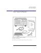
Setting Up the Infiniium DCA Step 5. Connect the Line Cord Step 5. Connect the Line Cord Connect the line cord as shown in the figure below. The Infiniium DCA automatically adjusts for line input voltages in the range of 100 to 240 VAC. There is no manual selection switch. The line cord provided is matched by Agilent to the country in which the order originates. Refer to Table 1-8, “Available Line Cords,” on page 1-13 for a list of available line power cords.
Setting Up the Infiniium DCA Step 5. Connect the Line Cord only a standby switch and is not a LINE switch. Alternatively, an externally installed switch or circuit breaker (which is readily identifiable and is easily reached by the operator) may be used as a disconnecting device. CAUTION Always use the three-prong AC power cord supplied with this instrument. Failure to ensure adequate earth grounding by not using this cord may cause instrument damage.
Setting Up the Infiniium DCA Step 5. Connect the Line Cord Table 1-8. Available Line Cords Plug Type Cable Part No. Plug Description Length (in/cm) Color Country 250V 8120-1689 Straight *CEE7-Y11 79/200 Mint Gray 8120-1692 90° 79/200 Mint Gray 8120-2857p Straight (Shielded) 79/200 Coco Brown East and West Europe, Saudi Arabia, So.
Setting Up the Infiniium DCA Step 6. Turn on the line power Step 6. Turn on the line power Press the power switch at the lower left-hand corner of the front panel. After about one minute, the Infiniium DCA will be ready to use. The display will look similar to the following figure.
Setting Up the Infiniium DCA Interacting With the Display NOTE The detachable power cord is the instrument disconnecting device. It disconnects the mains circuits from the mains power supply before other parts of the instrument. The front panel switch is only a standby switch and is not a LINE switch disconnecting device. Install the instrument so that the detachable power cord is readily identifiable and is easily reached by the operator.
Setting Up the Infiniium DCA Step 7. Set the time and date Step 7. Set the time and date 1 Touch the current time and date shown near the top of the display. The Set Time and Date dialog box opens. 2 Enter the current time and date in one of the following ways: • Click the time and date text boxes, and enter the desired number. • Click the up or down arrows next to the time and date text boxes until the desired number is displayed.
Setting Up the Infiniium DCA Step 8. Connect a Printer Step 8. Connect a Printer Use of a printer with the Infiniium DCA is optional. Table 1-9 lists the PCL-language printers that are currently supported for use with the instrument. To add a local printer, you must use the Add Printer Wizard to select the printer driver for the printer as outlined in this procedure; the Add Printer Wizard does not run automatically.
Setting Up the Infiniium DCA Step 8. Connect a Printer 3 Turn the power off the Infiniium DCA. Do not exit the online Help before turning the instrument off. 4 Connect the printer to the instrument’s rear-panel Parallel port. Refer to “Rear-panel features” on page 3-6 to locate the Parallel port. Use the cable that came with your printer. 5 Turn the printer power on. 6 Wait five seconds and then turn the power on the Infiniium DCA again. 7 The following message appears. Touch No.
Setting Up the Infiniium DCA Step 8. Connect a Printer 10 Select Local printer and then touch Next. 11 Select the printer manufacturer and then printer. Then, touch Next. If your printer is not listed, touch Have Disk. The instrument will then prompt you to put your printer driver disk into the front-panel disk drive (drive A) or CD-Rom drive. Be sure to install the Windows 98 printer driver for your printer. 12 Select LPT1 for the printer port. Touch Next.
Setting Up the Infiniium DCA Step 8. Connect a Printer 13 Touch Yes and then touch Next. 14 Touch Yes to print a test page. Then, touch Next. 15 After confirming that the test page printed correctly, touch Yes. 16 Turn the Infiniium DCA’s power off and then on again. The printer is now installed and ready to use.
Setting Up the Infiniium DCA Step 9. Calibrate the Touch Screen Step 9. Calibrate the Touch Screen The touch screen configuration utility ensures that the touch screen is both aligned and orientated with the display. Therefore, when you touch an element on the display screen, the instrument can detect the task you want to perform. 1 On the Utilities menu, choose Touch Screen Calibration. The touch screen configuration utility opens. 2 Touch the center of the X.
Setting Up the Infiniium DCA Step 10. Configure the Instrument on a LAN Step 10. Configure the Instrument on a LAN You can configure this instrument on a LAN for file sharing and using network printers. Contact your company’s network administrator to set up your instrument with the appropriate client, protocol, and configuration for your local area network (LAN). The network setup is different for every company.
Setting Up the Infiniium DCA Step 11. Avoid Costly Repairs Step 11. Avoid Costly Repairs CAUTION Electrical channel input circuits and the trigger input circuit can be damaged by electrostatic discharge (ESD). Therefore, avoid applying static discharges to the front-panel input connectors. Prior to connecting any coaxial cable to the connectors, momentarily short the center and outer conductors of the cable together.
Setting Up the Infiniium DCA Step 11. Avoid Costly Repairs and compromised measurements. Before you connect any fiber-optic cable to the Infiniium DCA, refer to “Cleaning Connections for Accurate Measurements” on page 1-30.
Setting Up the Infiniium DCA Step 12. Perform a Module Calibration Step 12. Perform a Module Calibration A module calibration establishes calibration factors for all installed modules. The calibration factors compensate for imperfections in the measurement system (for example, variations due to ambient temperature), resulting in the best instrument precision. It is recommended that you perform this calibration routinely for best measurement accuracy.
Setting Up the Infiniium DCA Step 12. Perform a Module Calibration To perform a module calibration 1 On the Calibrate menu, choose All Calibrations. The All Calibrations dialog box opens. This dialog box allows you to view the calibration status of modules and initiate the calibration. 2 Touch the Modules tab. The Modules tab opens and allows you to perform a module calibration on either the left or right module.
Setting Up the Infiniium DCA Step 12. Perform a Module Calibration module calibration is valid.
Setting Up the Infiniium DCA Step 13. For More Information Step 13. For More Information There are several ways to learn more about your Infiniium DCA. • Continue reading this book. Chapter 3, “Using the Infiniium DCA” will help you get started using this instrument. • Refer to the Help. The Help contains the information that would normally be in the user’s guide. • Visit our website at http://www.agilent.com.
Setting Up the Infiniium DCA Cleaning Connections for Accurate Measurements Cleaning Connections for Accurate Measurements Today, advances in measurement capabilities make connectors and connection techniques more important than ever. Damage to the connectors on calibration and verification devices, test ports, cables, and other devices can degrade measurement accuracy and damage instruments.
Setting Up the Infiniium DCA Choosing the Right Connector tions take repeatability uncertainty into account? • Will a connector degrade the return loss too much, or will a fusion splice be required? For example, many DFB lasers cannot operate with reflections from connectors. Often as much as 90 dB isolation is needed. Figure 1-1. Basic components of a connector. Over the last few years, the FC/PC style connector has emerged as the most popular connector for fiber-optic applications.
Setting Up the Infiniium DCA Choosing the Right Connector Figure 1-2. Universal adapters to Diamond HMS-10. The HMS-10 encases the fiber within a soft nickel silver (Cu/Ni/Zn) center which is surrounded by a tough tungsten carbide casing, as shown in Figure 1-3. Figure 1-3. Cross-section of the Diamond HMS-10 connector. The nickel silver allows an active centering process that permits the glass fiber to be moved to the desired position.
Setting Up the Infiniium DCA Inspecting Connectors glass face is not affected, scratches or grit can cause the glass fiber to move out of alignment. Also, if unkeyed connectors are used, the nickel silver can be pushed onto the glass surface. Scratches, fiber movement, or glass contamination will cause loss of signal and increased reflections, resulting in poor return loss.
Setting Up the Infiniium DCA Inspecting Connectors Figure 1-4. Clean, problem-free fiber end and ferrule. Figure 1-5. Dirty fiber end and ferrule from poor cleaning. Figure 1-6. Damage from improper cleaning. While these often work well on first insertion, they are great dirt magnets. The oil or gel grabs and holds grit that is then ground into the end of the fiber.
Setting Up the Infiniium DCA Inspecting Connectors nectors, using small glass spheres. When used with contacting connectors, these glass balls can scratch and pit the fiber. If an index matching gel or oil must be used, apply it to a freshly cleaned connector, make the measurement, and then immediately clean it off. Never use a gel for longer-term connections and never use it to improve a damaged connector.
Setting Up the Infiniium DCA Cleaning Connectors duce a good return-loss measurement. The quality of the polish establishes the difference between the “PC” (physical contact) and the “Super PC” connectors. Most connectors today are physical contact which make glass-to-glass connections, therefore it is critical that the area around the glass core be clean and free of scratches.
Setting Up the Infiniium DCA Cleaning Connectors Table 1-10. Cleaning Accessories Item Agilent Part Number Isopropyl alcohol 8500-5344 Cotton swabs 8520-0023 Small foam swabs 9300-1223 Compressed dust remover (non-residue) 8500-5262 Table 1-11.
Setting Up the Infiniium DCA Cleaning Connectors filtered, dry, compressed air. Aim the compressed air at a shallow angle to the fiber end face. Nitrogen gas or compressed dust remover can also be used. CAUTION Do not shake, tip, or invert compressed air canisters, because this releases particles in the can into the air. Refer to instructions provided on the compressed air canister. 7 As soon as the connector is dry, connect or cover it for later use.
Setting Up the Infiniium DCA Returning the Instrument for Service Returning the Instrument for Service The instructions in this section show you how to properly package the instrument for return to a Agilent Technologies service office. For a list of offices, refer to “Agilent Technologies Service Offices” on page 1-43.
Setting Up the Infiniium DCA Preparing the instrument for shipping information should be returned with the instrument. • Type of service required. • Date instrument was returned for repair. • Description of the problem: • Whether problem is constant or intermittent. • Whether instrument is temperature-sensitive. • Whether instrument is vibration-sensitive. • Instrument settings required to reproduce the problem. • Performance data. • Company name and return address.
Setting Up the Infiniium DCA Preparing the instrument for shipping Sealed Air Corporation (Commerce, California 90001). Air Cap looks like a plastic sheet filled with air bubbles. Use the pink (antistatic) Air Cap™ to reduce static electricity. Wrapping the instrument several times in this material will protect the instrument and prevent it from moving in the carton. 4 Seal the carton with strong nylon adhesive tape. 5 Mark the carton “FRAGILE, HANDLE WITH CARE”. 6 Retain copies of all shipping papers.
Setting Up the Infiniium DCA Hard Drive Recovery Hard Drive Recovery The Infiniium DCA hard drive recovery system offers a way to recover from situations when the instrument hard drive configuration becomes corrupt due to inadvertent user changes to the instrument or to a virus infection. The Infiniium DCA hard disk recovery system consists one floppy disk, one CD-ROM, and instructions. The recovery process will re-image the internal disk drive on the Agilent 86100B.
Setting Up the Infiniium DCA Agilent Technologies Service Offices Agilent Technologies Service Offices Call Center For technical assistance, you can contact your local Agilent Call Center. • In the Americas, call 1 (800) 452-4844 • In other regions, visit http://www.agilent.com and click Contact Us. Service Center Before returning an instrument for service, you must first call the Agilent Technologies Instrument Support Center.
Setting Up the Infiniium DCA Service Center 1-44
2 Working in Comfort
Working in Comfort Working in Comfort Working in Comfort To optimize your comfort and productivity, it is important that you set up your work area correctly and use your Agilent product properly. With that in mind, we have developed some setup and use recommendations for you to follow based on established ergonomic principles. Improper and prolonged use of keyboards and input devices are among those tasks that have been associated with repetitive strain injury (RSI) to soft tissues in the hands and arms.
Working in Comfort Mice and Other Input Devices RSI has also been observed in those who frequently engage in activities such as carpentry, knitting, housework, gardening, tennis, windsurfing and lifting children. What causes RSI? The specific causes of RSI have not been established. Nevertheless, the incidence of RSI has been associated with a variety of risk factors, including: • Too many uninterrupted repetitions of an activity or motion. • Performing an activity in an awkward or unnatural posture.
Working in Comfort Mice and Other Input Devices in your hands, wrists, and forearms. • If you are using a scrolling mouse, be sure to keep your fingers and hand in a relaxed, neutral position when activating the scroll wheel. Also, this type of mouse features software that can minimize the number of mouse movements or button clicks.
3 Introduction 3-2 Oscilloscope Mode 3-8 Eye/Mask Mode 3-7 TDR/TDT Mode 3-9 Using Plug-in Modules 3-10 Using the Touch Screen 3-12 Using the Quick Measure Feature 3-13 If the Display Goes Blank 3-14 Hiding and Moving Dialog Boxes 3-15 Menus 3-16 Using the Infiniium DCA
Using the Infiniium DCA Introduction Introduction The Infiniium DCA is designed to measure a variety of high speed digital communication waveforms. You can operate it in any of the following three instrument modes: • Eye/Mask Mode (100 Mb/s to 10 Gb/s) for eye diagram analysis and standards testing (for example, SONET/SDH, Gigabit Ethernet, and Fiber Channel).
Using the Infiniium DCA Introduction Use the touch screen You can explore the instrument’s menus and change its settings by touching the display. Notice that the measurement toolbar changes depending on the selected instrument mode. Touch the channel, time and delay, and trigger level buttons located at the bottom of the display to change the horizontal and vertical scales. Or, you can change these settings using front-panel knobs and buttons.
Using the Infiniium DCA Introduction Refer to the Help System To learn how to use your Infiniium DCA and to locate information on specifications (including plug-in modules), instrument features, and measurement configuration refer to Chapter 4, “Using the Built-In Information System” in this book.
Using the Infiniium DCA Introduction Front-panel features The following figure shows the input connectors, controls, power switch, and other front-panel features available on the Infiniium DCA.
Using the Infiniium DCA Introduction Rear-panel features The following figure shows the rear-panel input connections available on the Infiniium DCA.
Using the Infiniium DCA Eye/Mask Mode Eye/Mask Mode The Eye/Mask mode allows you to perform NRZ (Non-Return to Zero), or RZ (Return to Zero) eye diagram measurements and eye mask tests. The eye diagram is typically produced by triggering the instrument with a synchronous clock signal. Eye/Mask mode measurements only work when an eye diagram, and not a pulse, is present on the screen. Measurements made on a pulse waveform while in Eye/Mask mode will fail.
Using the Infiniium DCA Oscilloscope Mode Oscilloscope Mode Use the Oscilloscope mode for pulse type waveforms that are triggered by an external signal. Oscilloscope mode measurements only work when a single valued waveform, and not an eye diagram, is present on the screen. When you select the Oscilloscope mode, the measurement toolbars shown here appear. These measurement toolbars include measurements such as rise time, fall time, overshoot, and Vp-p.
Using the Infiniium DCA TDR/TDT Mode TDR/TDT Mode The TDR/TDT mode allows you use time domain reflectometry (TDR) to verify the proper functioning of the physical components of your device under test using a time-delayed electrical pulse. You can also use time domain transmission (TDT) to measure both the attenuation and propagation delay of your device under test. TDR/TDT mode measurements when using a single-ended or differential TDR/TDT 5475x series plug-in module.
Using the Infiniium DCA Using Plug-in Modules Using Plug-in Modules The Infiniium DCA holds up to two plug-in modules, which can provide up to four measurement channels. Each input channel has its own vertical controls. The amplitude scale knob adjusts the amplitude scale used for the input channel. Use the amplitude offset knob to position the displayed signal. You can also set the amplitude scale and offset to specific values by touching of channel buttons shown to at the bottom of the display.
Using the Infiniium DCA Using Plug-in Modules You can use 8348x and 5475x series plug-in modules In addition to a complete line of modules designed specifically for this instrument, modules designed for use with HP/Agilent 83480A and 54750A mainframes can also be installed into the Infiniium DCA. The 8348x and 5475x series plug-in modules are equipped with a trigger input on the individual module front panels.
Using the Infiniium DCA Using the Touch Screen Using the Touch Screen There may be times when you would like to disable the touch screen feature. For example, when pointing out a measurement result without initiating a change to the instrument. You can temporarily disable the touch screen for this purpose. A touch screen configuration utility can be used to ensure that the touch screen is both aligned and orientated with the display.
Using the Infiniium DCA Using the Quick Measure Feature Using the Quick Measure Feature Press Quick Measure and the Infiniium DCA automatically performs four measurements on a displayed signal. You can configure Quick Measure to include any four measurements located on the measurement tool bar. Quick Measure has a default set of measurements for each instrument mode. For example, in Oscilloscope mode the default measurements are: rise time, fall time, period, and V amplitude.
Using the Infiniium DCA If the Display Goes Blank If the Display Goes Blank The display automatically turns off if the Infiniium DCA is powered over an eight hour period without being used. The purpose of this feature is to extend the life of the display. You can adjust the amount of time that must elapse before the screen is turned off by the backlight saver utility (for example, 2, 4, 6, or 8 hours).
Using the Infiniium DCA Hiding and Moving Dialog Boxes Hiding and Moving Dialog Boxes Sometimes, dialog boxes may cover portions of a displayed signal and graticule that you wish to see. You can either move the dialog box or make it transparent. To move a dialog box • Touch the top of the dialog box, and drag your finger across of display to move the dialog box to a more convenient location. To make a dialog box transparent 1 Select Dialog Boxes from the Setup menu. 2 Touch Opaque or Transparent.
Using the Infiniium DCA Menus Menus The instrument menus provide access to all functions. This section shows the layout of each menu. For detailed information on each of these menus, refer to the Help.
Using the Infiniium DCA Menus The Control menu 3-17
Using the Infiniium DCA Menus The Setup menu 3-18
Using the Infiniium DCA Menus The Measure menu The Calibrate menu 3-19
Using the Infiniium DCA Menus The Utilities menu The Help menu 3-20
4 The Infiniium DCA Help Contents 4-3 Description of the Contents Topics 4-4 Getting Help While Changing Instrument Settings Learning About Measurements Results 4-7 Hiding the Help 4-8 Printing the Contents of a Topic 4-9 Selecting the Help Language 4-10 4-6 Using the Built-In Information System
Using the Built-In Information System Using the Built-In Information System Using the Built-In Information System Where is the operating manual for your infiniium DCA? It is built into your instrument! To access the built-in information system, referred to as Help, simply touch Contents on the Help menu. This will open the contents topic that is shown in the figure on the following page.
Using the Built-In Information System The Infiniium DCA Help Contents The Infiniium DCA Help Contents The following figure shows the 86100B Help contents. This is the starting point for learning how to use your Infiniium DCA. In addition to the 11 topics presented in the contents, be sure to use the index buttons located along the bottom of the topic window. These can be very helpful in locating a topic of interest.
Using the Built-In Information System Description of the Contents Topics Description of the Contents Topics The following list describes the information you can find in each of the contents topics. This topic contains links to useful information you may want to read first. Getting Started This topic contains links to utilizing the instrument functionality. Using the Instrument This topic provides step-by-step procedures for many configuration and measurement tasks.
Using the Built-In Information System Description of the Contents Topics This topic provides information about optical and electrical connector care. Connector Care This topic provides information about file management, using your network, and printing. Managing Files and Networks This topic contains descriptions of all instrument mainframe specifications. Instrument Specifications This topic provides a list of terms and their definitions. Glossary This topic provides technical support information.
Using the Built-In Information System Getting Help While Changing Instrument Settings Getting Help While Changing Instrument Settings Help is available directly from dialog boxes in the graphical user interface. • To see overview information in an open dialog box, touch the Book icon. A topic window opens and describes the dialog box and its controls. • To get information on a specific item in the dialog box, touch the What’s this? icon. Then touch the desired control on the dialog box.
Using the Built-In Information System Learning About Measurements Results Learning About Measurements Results After a measurement is performed, the displays shows the Measure tab which includes the measurement results. The fastest way to get help on measurement configuration or algorithms is to touch the Setup & Info button. The following figure shows the location of this button.
Using the Built-In Information System Hiding the Help Hiding the Help When using the Help, you can temporarily hide it so that you can see the entire display. Then, you can re-display the Help with the same topic still showing. • To hide the Help, touch the Minimize button located at the top of the Help window. • To re-display the Help, touch the Restore button that is shown on the display.
Using the Built-In Information System Printing the Contents of a Topic Printing the Contents of a Topic You can print the entire contents of a Help topic or a pop-up window. To print the entire contents of a Help topic, simply touch the Print button located at the top of the Help window. To print the entire contents of a pop-up Help window, by following the steps below. 1 Connect a printer and a mouse pointing device to the Infiniium DCA.
Using the Built-In Information System Selecting the Help Language Selecting the Help Language Help is available in more than one language. On the Help menu, touch Select Help Language, and then touch the language you want to view. Please ensure that the Help file is closed before changing the language selection. You can only view one version of help at a time. Help Version Refer to the English version of help to view the most current information about instrument features and specifications.
5 Regulatory Information
Regulatory Information Compliance with German Noise Requirements Compliance with German Noise Requirements This is to declare that this instrument is in conformance with the German Regulation on Noise Declaration for Machines (Laermangabe nach der Maschinenlaermrerordnung -3.GSGV Deutschland). Notice for Germany: Noise Declaration Acoustic Noise Emission Geraeuschemission LpA < 70 dB LpA < 70 dB Operator position am Arbeitsplatz Normal position normaler Betrieb per ISO 7779 nach DIN 45635 t.
Regulatory Information Declaration of Conformity - Mainframe Declaration of Conformity - Mainframe 5-3
Regulatory Information Declaration of Conformity - Plug-in Modules Declaration of Conformity - Plug-in Modules 5-4
Index Numerics 12 GHz trigger bandwidth, 1–6 5475x series plug-in modules, 3–11 8348x series plug-in modules, 3–11 contents topic, 4–3 cotton swabs, 1–37 CSA mark, 1–4 D A accessories connecting, 1–11 adapters APC 3.
Index instrument modes, 3–2 ISM1-A, 1–4 isopropyl alcohol, 1–37 K keyboard, 1–6, 1–11 L LAN, 1–23 language version, 4–10 line cords, 1–13 line power requirements, 1–15 M Measure menu, 3–17 measurement channels, 3–10 measurement results, 4–7 measurement toolbar, 3–3 measurement toolbars, 3–7, 3–8, 3–9 menu bar, 3–16 Minimize button, 4–8 module calibration, 1–26 module, installing, 3–10 modules, installing, 1–9 mouse, 1–6, 1–11 N network printers, 1–23 network setup, 1–23 noise declaration, 5–2 O online
Index U Utilities menu, 1–22 W warm-up time, 1–26 Web site, Agilent, 1–29 weight, 1–10 What’s this? icon, 4–6 wire bail, positioning, 1–11 Index-3
Index Index-4