Agilent 81480A and Agilent 81680A, 81640A, 81682A, 81642A, & 81689A Tunable Laser Modules User’s Guide S1
Notices This document contains proprietary information that is protected by copyright. All rights are reserved. No part of this document may reproduced in (including electronic storage and retrieval or translation into a foreign language) without prior agreement and written consent from Agilent Technologies Deutschland GmbH as governed by United States and international copywright laws. Copyright 2001 by: Agilent Technologies Deutschland GmbH Herrenberger Str.
Safety Summary Safety Summary The following general safety precautions must be observed during all phases of operation, service, and repair of this instrument. Failure to comply with these precautions or with specific warnings elsewhere in this manual violates safety standards of design, manufacture, and intended use of the instrument. Agilent Technologies Inc. assumes no liability for the customer’s failure to comply with these requirements.
Safety Summary WARNING You MUST return instruments with malfunctioning laser modules to an Agilent Technologies Sales/Service Center for repair and calibration. Line Power Requirements The Agilent 81480A, Agilent 81680A, Agilent 81640A, Agilent 81682A, Agilent 81642A, & Agilent 81689A Tunable Laser Modules operate when installed in the Agilent 8164A Lightwave Measurement System.
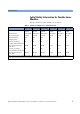
Safety Summary Initial Safety Information for Tunable Laser Modules The Specifications for these modules are as follows: Table 1 Tunable Laser Modules Laser Safety Information Agilent 81480A Agilent 81680A Agilent 81640A Agilent 81682A Agilent 81642A Agilent 81689A Laser Type FP-Laser InGaAsP FP-Laser InGaAsP FP-Laser InGaAsP FP-Laser InGaAsP FP-Laser InGaAsP FP-Laser InGaAsP Wavelength range 1370-1480 nm 1400-1670 nm 1400-1670 nm 1400-1670 nm 1400-1670 nm 1400-1670 nm Max.
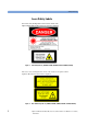
Safety Summary Laser Safety Labels These laser safety warning labels are fixed on the outside of the Agilent 8164A Lightwave Measurement System before shipment. Figure 1 USA Safety Labels (81480A, 81680A, 81640A, 81682A, 81642A, 81689A) These laser safety warning labels are fixed on the outside of the Agilent 8164A Lightwave Measurement System before shipment.
Safety Summary A sheet of laser safety warning labels are included with the instrument. You MUST stick the labels in the local language onto the outside of the instrument, in a position where they are clearly visible to anyone using the instrument.
Safety Summary WARNING Please pay attention to the following laser safety warnings: • Under no circumstances look into the end of an optical cable attached to the optical output when the device is operational. The laser radiation can seriously damage your eyesight. • Do not enable the laser when there is no fiber attached to the optical output connector. • The laser is enabled by pressing the gray button close to the optical output connector on the front panel of the module.
The Structure of this Manual The Structure of this Manual This manual is divided into two categories: • Getting Started This section gives an introduction to the Tunable Laser modules. and aims to make these modules familiar to you: – “Getting Started with Tunable Laser Sources” on page 21. • Additional Information This is supporting information of a non-operational nature.
The Structure of this Manual 10 Agilent 81480A and 81680A, 40A, 82A, 42A, & 89A Tunable Laser Modules User’s Guide, Sixth Edition
Table of Contents Table of Contents Safety Summary Safety Symbols Initial Inspection Line Power Requirements Operating Environment Input/Output Signals Storage and Shipment Initial Safety Information for Tunable Laser Modules Laser Safety Labels The Structure of this Manual 3 3 3 4 4 4 4 5 6 9 Conventions used in this manual 9 Getting Started with Tunable Laser Sources 21 What is a Tunable Laser ? 23 Agilent 81480A, 81680A/82A/40A/42A Tunable Laser Modules 24 Agilent 81689A Tunable Laser Module
Table of Contents Options 072, 022: Angled Contact Connectors Specifications 39 Definition of Terms Absolute Wavelength Accuracy Effective Linewidth Linewidth Minimum Output Power Mode-Hop Free Tuning Range Modulation Extinction Ratio Modulation Frequency Range Output Power Output Isolation Peak Power Polarization Extinction Ratio Power Flatness Over Modulation Power Flatness Versus Wavelength Power Linearity Power Repeatability Power Stability Relative Intensity Noise (RIN) Relative Wavelength Accuracy
Table of Contents Stepped Mode (Agilent 81680A/40A/82A/42A) General Output Isolation (typ.): Return loss (typ.
Table of Contents 81 Signal-to-Source Spontaneous Emission Tests - Low SSE Outputs 83 Signal-to-Total-Source Spontaneous Emission Signal to Total SSE Tests - Low SSE Outputs Optional Test Signal to Total SSE Tests - High Power Outputs Test Record 88 89 95 95 99 Agilent 81480A Performance Test Test Equipment Used 99 Agilent 81680A Performance Test Test Equipment Used 113 100 Relative Wavelength Accuracy 101 Mode Hop Free Tuning 103 Wavelength Repeatability 104 Maximum Power Test 105 Power Linearity
Table of Contents Output 2, High Power 125 Agilent 81640A Performance Test 127 Test Equipment Used 128 Relative Wavelength Accuracy 129 Relative Wavelength Accuracy Summary of all Repetitions 130 Relative Wavelength Accuracy Result 130 Absolute Wavelength Accuracy Result 130 Mode Hop Free Tuning 131 Wavelength Repeatability 132 Maximum Power Test 133 Power Linearity Output 1, Low SSE134 Power Linearity Output 2, High Power Upper Power Levels 134 Power Linearity Output 2, High Power by Attenuator 135 Pow
Table of Contents Power Linearity 81642A #003 by Attenuator 161 Power Flatness 162 Power Stability 163 Signal-to-Source Spontaneous Emission - 81642A 163 Optional Test: Signal-to-Total-Source Spontaneous Emission - 81642A 164 Agilent 81689A Performance Test Test Equipment Used Relative Wavelength Accuracy Wavelength Repeatability Maximum Power Test Power Linearity Power Flatness Power Stability Signal-to-Source Spontaneous Emission Cleaning Information 166 167 168 169 169 170 170 170 171 Safety Precaut
Table of Contents 183 How to clean bare fiber adapters How to clean lenses 184 How to clean instruments with a fixed connector interface 184 How to clean instruments with an optical glass plate 185 How to clean instruments with a physical contact interface 185 How to clean instruments with a recessed lens interface 186 How to clean optical devices which are sensitive to mechanical stress and pressure How to clean metal filters or attenuator gratings Additional Cleaning Information How to clean bare fibe
Table of Contents 18 Agilent 81480A and 81680A, 40A, 82A, 42A, & 89A Tunable Laser Modules User’s Guide, Sixth Edition
List of Figures List of Figures Figure 1 Figure 2 Figure 3 Figure 4 Figure 5 Figure 6 Figure 7 Figure 8 Figure 9 Figure 10 Figure 11 Figure 12 Figure 13 Figure 14 Figure 15 Figure 16 Figure 17 Figure 18 Figure 19 Figure 20 Figure 21 Figure 22 Figure 23 Figure 24 Figure 25 USA Safety Labels (81480A, 81680A, 81640A, 81682A, 81642A, 81689A) . . Non-USA Safety Labels (81480A, 81680A, 81640A, 81682A, 81642A, 81689A) Position of Safety Labels on Backloadable Tunable Laser Modules . . .
List of Figures 20 Agilent 81480A and 81680A, 40A, 82A, 42A, & 89A Tunable Laser Modules User’s Guide, Sixth Edition
Getting Started with Tunable Laser Sources Agilent 81480A and 81680A, 40A, 82A, 42A, & 89A Tunable Laser Modules User’s Guide, Sixth Edition 21
Getting Started with Tunable Laser Sources This chapter describes the Agilent 81480A, Agilent 81680A, Agilent 81640A, Agilent 81682A, Agilent 81642A, and Agilent 81689A Tunable Laser modules.
What is a Tunable Laser ? Getting Started with Tunable Laser Sources What is a Tunable Laser ? A Tunable Laser is a laser source for which the wavelength can be varied through a specified range. The Agilent Technologies range of Tunable Laser modules also allow you to set the output power, and to choose between continuous wave or modulated power.
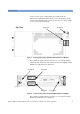
Getting Started with Tunable Laser Sources What is a Tunable Laser ? Agilent 81480A, 81680A/82A/40A/42A Tunable Laser Modules 24 Figure 5 Agilent 81480A Tunable Laser Module (straight contact connectors) Figure 6 Agilent 81680A Tunable Laser Module (straight contact connectors) Figure 7 Agilent 81682A Tunable Laser Module (straight contact connector) Figure 8 Agilent 81640A Tunable Laser Module (straight contact connectors) Figure 9 Agilent 81642A Tunable Laser Module (straight contact connecto
What is a Tunable Laser ? Getting Started with Tunable Laser Sources The Agilent 81480A and 81680A/82A/40A/42A Tunable Laser modules are back-loadable modules. To fit these modules into the Agilent 8164A mainframe see “How to Fit and Remove Modules” in the Agilent 8163A Lightwave Multimeter, Agilent 8164A, Lightwave Measurement System, & Agilent 8166A Lightwave Multichannel SystemUser’s Guide.
Getting Started with Tunable Laser Sources What is a Tunable Laser ? Agilent 81689A Tunable Laser Module Agilent 81689A with Straight Contact Connector Figure 10 Agilent 81689A with Angled Contact Connector Agilent 81689A Tunable Laser Module The Agilent 81689A Tunable Laser module is a front-loadable module.
Optical Output Getting Started with Tunable Laser Sources Optical Output Polarization Maintaining Fiber If you have an instrument with a polarization maintaining fiber (PMF), the PMF is aligned to maintain the state of polarization. The fiber is of Panda type, with TE mode in the slow axis in line with the connector key. A well defined state of polarization ensures constant measurement conditions. The Agilent 81480A and 81680A/40A/82A/42A Tunable Laser modules are equipped with PMF outputs as standard.
Getting Started with Tunable Laser Sources Optical Output Two additional connector interface options are available for the Agilent 81689A Tunable Laser module: • Option 021, Standard single-mode fiber straight contact connectors, or • Option 022, Standard single-mode fiber angled contact connectors. C A U TI O N If the contact connector on your instrument is angled, you can only use cables with angled connectors with the instrument.
Signal Input and Output Getting Started with Tunable Laser Sources Signal Input and Output CA U TI O N There are two BNC connectors on the front panel of the Agilent 81480A, Agilent 81680A, Agilent 81680A, Agilent 81640A, Agilent 81682A, and Agilent 81642A - a BNC input connector and a BNC output connector. There is one BNC connector on the front panel of the Agilent 81689A a BNC input connector. An absolute maximum of ±6 V can be applied as an external voltage to any BNC connector.
Getting Started with Tunable Laser Sources 30 Signal Input and Output Agilent 81480A and 81680A, 40A, 82A, 42A, & 89A Tunable Laser Modules User’s Guide, Sixth Edition
Accessories Agilent 81480A and 81680A, 40A, 82A, 42A, & 89A Tunable Laser Modules User’s Guide, Sixth Edition 31
Accessories The Agilent 81480A and 81680A/40A/82A/42A/89A Tunable Laser Source Modules are available in various configurations for the best possible match to the most common applications. This chapter provides information on the available options and accessories.
Modules and Options Accessories Modules and Options Figure 14 shows all the options that are available for all Tunable Laser modules and the instruments that support these modules.
Accessories Modules Modules The Agilent 8164A Lightwave Measurement System supports the Agilent 81480A and 81680A/40A/82A/42A/89A Tunable Laser modules. In addition, the Agilent 8163A Lightwave Multimeter supports the Agilent 81689A Tunable Laser module. Tunable Laser Modules Model No.
Modules Accessories User’s Guides User’s Guides Opt Description Part No.
Accessories Connector Interfaces and Other Accessories Option 022 - Agilent 81689A Standard single-mode fiber, for angled contact connectors. Option 071 - All Tunable Laser Modules Polarization-maintaining fiber, Panda-type, for straight contact connectors. Option 072 - All Tunable Laser Modules Polarization-maintaining fiber, Panda-type, for angled contact connectors.
Connector Interfaces and Other Accessories Accessories 1 Attach your connector interface to the interface adapter. See Table 2 for a list of the available connector interfaces. 2 Connect your cable (see Figure 15).
Accessories Connector Interfaces and Other Accessories 2 Connect your cable (see Figure 16). Agilent 8100 Agilent 8100 Agilent 8100 Agilent 8100 0NI 0KI 0HI 0SI Connector Connector Connector Connector Interface Interface Interface Interface DIN FC/APC SC/APC Diamond 47256/4108.6 E-2108.6 Figure 16 Table 3 38 Options 022, 072: Single-mode fiber/PMF with Angled Contact Connectors Angled Contact Connector Interfaces Description Model No. DIN 47256-4108.
Specifications Agilent 81480A and 81680A, 40A, 82A, 42A, & 89A Tunable Laser Modules User’s Guide, Sixth Edition 39
Specifications The Agilent 81480A, Agilent 81680A, Agilent 81640A, Agilent 81682A, Agilent 81642A and Agilent 81689A Tunable Laser modules are produced to the ISO 9001 international quality system standard as part of Agilent Technologies’ commitment to continually increasing customer satisfaction through improved quality control. Specifications describe the modules’ warranted performance. Supplementary performance characteristics describe the modules non-warranted typical performance.
Definition of Terms Specifications Definition of Terms This section defines terms that are used both in this chapter and “Performance Tests” on page 57. Generally, all specifications apply for the given environmental conditions and after warmup time. Measurement principles are indicated. Alternative measurement principles of equal value are also acceptable. Absolute Wavelength Accuracy The maximum difference between the actual wavelength and the displayed wavelength of the TLS.
Specifications Definition of Terms Measurement with heterodyning technique: the output of the laser under test is mixed with another laser of the same type on a wide bandwidth photodetector. The electrical noise spectrum of the photodetector current is measured with an Agilent Lightwave Signal Analyzer, and the linewidth is calculated from the heterodyne spectrum (Lightwave signal analyzer settings: resolution bandwidth 1 MHz; video bandwidth 10 kHz; sweep time 20 ms; single scan).
Definition of Terms Specifications Measurement with optical spectrum analyzer. Tunable laser switched on and off. Modulation Frequency Range The range of frequencies for which the modulation index is above − 3 dB of the highest modulation index. In this context, modulation index is defined as the AC power amplitude (peak-to-peak) divided by the average power. Output Power The achievable output power for the specified TLS tuning range. Conditions: temperature within operating temperature range.
Specifications Definition of Terms Power Flatness Over Modulation When changing the wavelength and modulation frequency, and measuring the differences between actual and displayed power levels (in dB), the power flatness is ± half the span between the maximum and the minimum value of all differences. Conditions: uninterrupted line voltage, constant power setting, temperature within ±2 K, external modulation ON. Measurement with optical power meter.
Definition of Terms Specifications Power Stability The change of the power level during given time span, expressed as ± half the span (in dB) between the highest and lowest actual power. Conditions: uninterrupted TLS output power, constant wavelength and power level settings, temperature within ±1 K, time span as specified. Measurement with optical power meter.
Specifications Definition of Terms Sidemode Suppression Ratio The ratio of average signal power to the optical power of the highest sidemode within a distance from 0.1 to 6 GHz to the signal's optical frequency, expressed in dB. Conditions: at a specified output power and wavelength range, temperature within operating temperature range, coherence control off. Measurement with the Agilent Lightwave Signal Analyzer, by analyzing the heterodyning between the main signal and the highest sidemode.
Definition of Terms Specifications NOTE The specified signal-to-total-SSE ratio is also applicable to output powers higher than the specified values. Wavelength Range The range of wavelengths for which the specifications apply. Wavelength Repeatability The random uncertainty in reproducing a wavelength after detuning and re-setting the wavelength. The wavelength repeatability is ± half the span between the maximum and the minimum value of all actual values of this wavelengths.
Specifications Tunable Laser Module Specifications Tunable Laser Module Specifications Agilent 81480A Agilent 81480A Agilent 81480A Output 1 (Low SSE) Output 2 (High Power) Wavelength range 1370 nm to 1480 nm Wavelength resolution 0.1 pm, 15 MHz at 1450 nm Mode-hop free tuning range 9 full wavelength range Absolute wavelength accuracy 1, 2, 9 ±0.01 nm Relative wavelength accuracy 1, 2, 9 ±5 pm, typ. ±2 pm Wavelength repeatability 2, 9 ±1 pm, typ. ±0.5 pm Wavelength stability (typ.
Tunable Laser Module Specifications Power flatness versus wavelength 3, 9 Specifications ±0.2 dB, typ. ±0.1 dB ±0.3 dB, typ. ±0.2 dB (1420-1480nm) ±0.2 dB typ (1370nm-1420nm) Side-mode suppression ratio (typ.) 4, 8, 9 > 40 dBc (1380 - 1480 nm) Signal-to-Source Spontaneous Emission Ratio 5, 8 > 61 dB/nm [7] Signal-to-Total-Source Spontaneous Emission ratio 6, 8 (1420 – 1470 nm) (1420nm-1480nm) ±0.3 dB typ (1370nm-1420nm) > 40 dB/ nm (1420 – 1470 nm) > 55 dB/nm [7] [9] (typ.
Specifications Tunable Laser Module Specifications Agilent 81680A and Agilent 81640A Wavelength range Agilent 81680A Agilent 81680A Agilent 81640A Agilent 81640A Output 1 (Low SSE) Output 2 (High Power) Output 1 (Low SSE) Output 2 (High Power) 1460 nm to 1580 nm Wavelength resolution 0.1 pm, 12.5 MHz at 1550 nm Mode hop free tuning range 1460 nm to 1580 nm 1510 nm to 1640 nm ± 0.01 nm ± 0.015 nm ± 5 pm, typ. ± 2 pm ± 7 pm, typ.
Tunable Laser Module Specifications Specifications Agilent 81680A Agilent 81680A Agilent 81640A Agilent 81640A Output 1 (Low SSE) Output 2 (High Power) Output 1 (Low SSE) Output 2 (High Power) Signal-to-Source Spontaneous Emission Ratio 5,8 ≥ 63 dB/nm7 (1520-1570 nm) ≥ 58 dB/nm7 (typ., 1480-1580 nm) ≥ 53 dB/nm7 (typ., 1460-1580 nm) ≥ 45 dB/nm (1520-1570 nm) ≥ 40 dB/nm (1480-1580 nm) ≥ 35 dB/nm (1460-1580 nm) ≥ 60 dB/nm7 (1530-1610 nm) ≥ 55 dB/nm7 (typ., 1520-1620 nm) ≥ 50 dB/nm7 (typ.
Specifications Tunable Laser Module Specifications Agilent 81682A, Agilent 81642A and Agilent 81689A Agilent 81682A Agilent 81642A Agilent 81689A Wavelength range 1460 nm to 1580 nm 1510 nm to 1640 nm 1525 nm to 1575 nm Wavelength resolution 0.1 pm, 12.5 MHz at 1550 nm 0.1 pm, 12.5 MHz at 1550 nm 0.01 nm, 1.25 GHz at 1550 nm Mode hop-free tuning range 1460 nm to 1580 nm full wavelength range Absolute wavelength accuracy ± 0.01 nm1, 2 ± 0.015 nm1, 2 ± 0.3 nm, typ.
Tunable Laser Module Specifications Specifications Agilent 81682A Agilent 81642A Agilent 81689A Side-mode Suppression ratio (typ.
Specifications Supplementary Performance Characteristics Supplementary Performance Characteristics Operating Modes Internal Digital Modulation 1 50% duty cycle, 200 Hz to 300 kHz. Modulation output: TTL reference signal. 1 Agilent 81480A, Agilent 81680A/40A/82/42A: displayed wavelength represents average wavelength while digital modulation is active. External Digital Modulation 1 > 45% duty cycle, fall time < 300 ns, 200 Hz to 1 MHz. Modulation input: TTL signal.
Supplementary Performance Characteristics Specifications Continuous Sweep (Agilent 81680A/40A/82A/42A) Tuning velocity adjustable to: 40 nm/s, 5 nm/s, 0.5 nm/s. Mode-hop free span: • Agilent 81480A: 1420 - 1470 nm at flat output power ≥ 0 dBm • Agilent 81680A/82A: 1520 - 1570 nm at flat output power ≥ 3 dBm • Agilent 81640A: Any 50 nm within 1520 - 1620 nm at flat output power ≥ 0 dBm • Agilent 81642A: Any 50 nm within 1520 - 1620 nm at flat output power ≥ 2 dBm Ambient temperature within +20°C and +30°C.
Specifications Supplementary Performance Characteristics Recalibration Period: 2 years. Warm-up Time: < 20 min (< 40 min for Agilent 81689A), immediate operation after boot-up. Environmental Storage Temperature: −40°C to +70°C. Operating Temperature: +10°C to +35°C (+15°C to +35°C for Agilent 81689A). Humidity: < 80% R. H. at +10°C to +35°C (+15×°C to +35°C for Agilent 81689A). Specifications are valid in non-condensing conditions.
Performance Tests Agilent 81480A and 81680A, 40A, 82A, 42A, & 89A Tunable Laser Modules User’s Guide, Sixth Edition 57
Performance Tests The procedures in this section tests the optical performance of the instrument. The complete specifications to which the Agilent 81480A, Agilent 81680A, Agilent 81640A, Agilent 81682A, Agilent 81642A and Agilent 81689A are tested are given in “Specifications” on page 39. All tests can be performed without access to the interior of the instrument. The performance tests refer specifically to tests using the Diamond HMS-10/Agilent connector.
Required Test Equipment Performance Tests Required Test Equipment The equipment required for the Performance Test is listed in Table Table 4. Any equipment which satisfies the critical specifications of the equipment given in Table Table 4, may be substituted for the recommended models.
Performance Tests Required Test Equipment Test Record Results of the performance test may be tabulated in the Test Record provided at the end of the test procedures. It is recommended that you fill out the Test Record and refer to it while doing the test. Since the test limits and setup information are printed on the Test Record for easy reference, the record can also be used as an abbreviated test procedure (if you are already familiar with the test procedures).
Performance Test Instructions Performance Tests Performance Test Instructions NOTE • Make sure that all fiber connectors are clean. • Turn the instruments on, enable the laser and allow the instruments to warm up. • Ensure that the Device Under Test (DUT) and all the test equipment is held within the environmental specifications given in “Specifications” on page 39 General Test Setup Insert your Tunable Laser module into the Agilent 8164A Lightwave Measurement System.
Performance Tests Performance Test Instructions General Settings of Wavelength Meters for all Wavelength Tests Set the Burleigh WA-150 to the following settings: • Set Display to Wavelength. • Set Medium to Vacuum. • Set Resolution to Auto. • Set Averaging to On. • Set Input Attenuator to Auto. Wavelength Accuracy The steps below explain how to calculate the Relative Wavelength Accuracy, Absolute Wavelength Accuracy, and the Mode Hop Free Tuning Result.
Performance Test Instructions Performance Tests Table 6 Initial Wavelength and Power Settings for Relative Wavelength Accuracy Tests Wavelength [λ] Power [P] Agilent 81480A 1370.200 nm −3.00 dBm Agilent 81680A 1460.000 nm −3.00 dBm Agilent 81640A 1510.000 nm −3.00d Bm Agilent 81682A 1460.000 nm −3.00 dBm Agilent 81682A (#003) 1460.000 nm −4.50 dBm Agilent 81642A 1510.000 nm −3.00 dBm Agilent 81642A (#003) 1510.000 nm −4.50 dBm Agilent 81689A 1525.000 nm −3.
Performance Tests Performance Test Instructions N O TE The largest Maximum Deviation is the largest positive value and the smallest Minimum Deviation is the largest negative value (largest deviation above and below zero respectively). 12 Determine the Relative Wavelength Accuracy Result: Subtract the Smallest Minimum Deviation from the Largest Maximum Deviation. Record this value as the Relative Wavelength Accuracy Result.
Performance Test Instructions Performance Tests 18 Press the key beside the laser output to switch on the laser output. 19 Then perform steps 4 through 8 once. 20 Note the wavelength displayed by the wavelength meter in the test record. 21 Increase wavelength setting on Tunable Laser by the steps shown in the test record. 22 Repeat steps 6 and 7 up to the maximum wavelength values shown in Table Table 7. 23 Pick the maximum and minimum deviations, and note these values in the test record.
Performance Tests Performance Test Instructions 6 Wait until the wavelength meter has settled. Then measure the wavelength with the wavelength meter and note the result in test record as the reference wavelength, "REF". 7 Set the wavelength of your Tunable Laser module to any wavelength in its range (in the test record, this is given in column “from wavelength”). 8 Set the wavelength of your Tunable Laser module back to the Reference Wavelength and wait until the wavelength meter has settled.
Performance Test Instructions Performance Tests Power Tests Calibration of the Agilent 81001FF Attenuation Filter NOTE When an HP 81524A Optical Head is used in conjunction with a Agilent 81001FF Attenuation Filter, it is absolutely necessary that you calibrate the Agilent 81001FF Attenuation Filter before starting the power tests in the following measurement setups; it is not sufficient to use calibration factors that are derived from an earlier setup. 1 Make sure all instruments have warmed up.
Performance Tests Performance Test Instructions 5 Check if the display of HP 8153A reads 0 dBm ±2 dBm. 6 Select dB as the power units of the HP 8153A. 7 Press Disp−>Ref on the HP 8153A. 8 Attach the Agilent 81001FF Attenuation Filter to the Optical Head as shown in Figure 19. Move the patchcord as little as possible, keeping the laser activated.
Performance Test Instructions Performance Tests Maximum Output Power Make sure the instruments have warmed up before starting the measurement. NOTE • Absolute Power Accuracy is not specified. • The result of the measurement below is greatly influenced by the quality and the matching of the used interconnections. 1 Set up the equipment as shown in Table Figure 20.
Performance Tests Performance Test Instructions 6 Set the wavelength and power for each Tunable Laser module to the values given in Table Table 10. Table 10 Reference Wavelength and Power Values for Maximum Output Power Tests Wavelength [λ] Power [P] Agilent 81480A - Output 1 1370.200 nm +0.00 dBm Agilent 81480A - Output 2 1370.200 nm +10.00 dBm Agilent 81680A - Output 1 1460.000 nm +0.00 dBm Agilent 81680A - Output 2 1460.000 nm +10.00 dBm Agilent 81640A - Output 1 1510.000 nm +0.
Performance Test Instructions Performance Tests Power Linearity Power Linearity - Low Power Test To measure the power linearity of the Low SSE output, Output 1, of the Agilent 81480A, Agilent 81680A, or the of the Agilent 81640A: 1 Set up the equipment as shown in Figure 21.
Performance Tests Performance Test Instructions 7 Set the HP 8153A to the following settings: a Zero the HP 81532A; press Zero. b Select automatic ranging; press Auto as required. c Set T, the averaging time, to 500 ms. d Select dB as the power units. e Set the l, the wavelength, to the same as your Tunable Laser module, as given in Table Table 11. 8 Press the key beside the laser output to switch on the laser output.
Performance Test Instructions Performance Tests Example (Agilent 81680A Output 1) Power LinearityOutput 1 Power Setting from start Start = REF Measured Relative Power from start Power reduction from start Power Linearity at current setting −6.0 dBm 0.00 dB + 0.00 dB = 0.00 dB −7.0 dBm −1.02 dB + 1.00 dB = −0.02 dB −8.0 dBm −1.92 dB + 2.00 dB = +0.08 dB −9.0 dBm −3.02 dB + 3.00 dB = −0.02 dB − 10.0 dBm −3.95 dB + 4.00 dB = +0.05 dB − 11.0 dBm −5.07 dB + 5.00 dB = −0.
Performance Tests Performance Test Instructions 3 Set the menu parameters to the values shown in Table Table 5. For Agilent 81480A, Agilent 81680A, Agilent 81640A, Agilent 81682A, and Agilent 81642A tunable lase modules: Set to . 4 Set the wavelength and power for each Tunable Laser module to the values given in Table Table 12.
Performance Test Instructions Performance Tests Power Linearity - Test Using Attenuation Follow the steps below to measure the power linearity (while using attenuation) of any one of the following: • Output 2, the High Power output, of the Agilent 81480A • Output 2, the High Power output, of the Agilent 81680A • Output 2, the High Power output, of the Agilent 81640A • Agilent 81682A #003 • Agilent 81642A #003 1 Set up the equipment as shown in Figure 21.
Performance Tests Performance Test Instructions Power Flatness over Wavelength Power Flatness over Wavelength - Without Attenuation Follow the steps below to measure the power flatness over wavelength (without using attenuation): 1 Set up the equipment as shown in Figure 21. 2 Move to the Tunable Laser channel of the Agilent 8164A Lightwave Measurement System and press [Menu]. 3 Set the menu parameters to the values shown in Table Table 5.
Performance Test Instructions Performance Tests c Set the l, the wavelength, to the same as your Tunable Laser module, as given in Table Table 14. d Select dB as the power units. 7 Press the DISP->REF hardkey of the HP 8153A. 8 Increase the wavelength of the Tunable Laser module and of the Power Meter to the next value listed in the test record. 9 Measure the output power. Note the result in the test record 10 Repeat steps 8 and 9 for the wavelength settings given in the test record.
Performance Tests Performance Test Instructions Table 15 Wavelength and Power Settings for Power Flatness over Wavelength Tests with Attenuation Wavelength [λ] Power [P] Attenuation [Atten] Agilent 81480A - Output 2 1420.000 nm −3.000 dBm 57.000 dB Agilent 81680A - Output 2 1460.000 nm −3.000 dBm 57.000 dB Agilent 81640A - Output 2 1510.000 nm −5.000 dBm 55.000 dB Agilent 81682A #003 1460.000 nm −4.500 dBm 55.500 dB Agilent 81642A #003 1510.000 nm −4.500 dBm 55.
Performance Test Instructions Performance Tests Power Stability Follow the steps below to measure the power stability: 1 Set up the equipment as shown in Figure 20. 2 Move to the Tunable Laser channel of the Agilent 8164A Lightwave Measurement System and press [Menu]. 3 Set the menu parameters to the values shown in Table Table 5. 4 Set the wavelength and power for each Tunable Laser module to the values given in Table Table 16.
Performance Tests Performance Test Instructions • Set HP 8153A to Logging, T_Total 15 minutes: a Press Menu. b Press Record to get STABILITY. c Press Edit to get T_TOTAL. d Modify the display until it shows 0:15:00. e N O TE Press Edit. To test power stability, it is sufficient to set T_Total to 15 minutes rather than 1 hour, to ensure that the power control loop works correctly. 8 Press the key beside the laser output to switch on the laser output and wait 1 minute.
Performance Test Instructions Performance Tests Signal-to-Source Spontaneous Emission See “Specifications” on page 39 for a definition of Signal-to-Source Spontaneous Emission.
Performance Tests Performance Test Instructions b Set the Resolution Bandwidth to 1 nm. Press [AMPL], press [BW Swp], and enter the value. c Set the Sensitivity to -60 dBm. Press [AMPL], press [SENS], and enter the value. d Set the wavelength to the value given for your Tunable Laser module in Table Table 17. 5 Move to the Tunable Laser channel of the Agilent 8164A Lightwave Measurement System and press [Menu]. 6 Set the menu parameters to the values shown in Table Table 5.
Performance Test Instructions Performance Tests Signal-to-Source Spontaneous Emission Tests - Low SSE Outputs Follow this procedure to test modules with Low SSE high power outputs: • Agilent 81480A, Output 1, Low SSE • Agilent 81680A, Output 1, Low SSE • Agilent 81640A, Output 1, Low SSE The previous setup is limited by the dynamic range of the Optical Spectrum Analyzer. An improvement can be done by reducing the power of the spectral line of the Tunable Laser module by a filter, a Fiber Bragg Grating.
Performance Tests Performance Test Instructions Figure 23 Transmission Characteristic of Fiber Bragg Grating Figure 24 Signal-to-Spectral SSE Measurement Lower Transmission Band λ1 ... λ2 Upper Transmission Band λ3 ... λ4 Attenuation Band λ2 ... λ3 < 2 nm 1 Connect the Tunable Laser module (DUT) to the Optical Spectrum Analyzer as shown in Figure 25. Connect the one end of the Fiber Bragg Grating (FBG)1 to Output 1, the Low SSE output, and the other to the Optical Spectrum Analyzer.
Performance Test Instructions Performance Tests Agilent 8164A Lightwave Measurement System Optical Spectrum Analyzer Fiber Bragg Grating Tunable Laser For #021, #071: use 81000FI and adapter DIN/DIN 1005-0255 and 81113PC and 81000FI For #022, #072: use 81000SI and 81000FI Figure 25 Test Setup for Source Spontaneous Emission Test 2 Determine the filter transmission characteristics: a Check center wavelength, lFBG, of the Fiber Bragg Grating.
Performance Tests Performance Test Instructions f Table 19 For lFBG ± 1 nm, check and note the power level displayed by the OSA at every 0.1 nm interval. That is, fill out the table shown in Table Table 19. Filter Transmission Characteristic Tunable Laser Module Output Wavelength Relative to λFBG Associated Wavelength Displayed on OSA Peak Power Level −1.0 nm dBm nm −0.9 nm dBm nm −0.8 nm dBm nm −0.7 nm dBm nm −0.6 nm dBm nm −0.5 nm dBm nm −0.4 nm dBm nm −0.3 nm dBm nm −0.
Performance Test Instructions Performance Tests c Mark the associated wavelength displayed on the OSA, OSA_l0, and note the value in the test record. 4 Set TLS to the wavelength of minimum transmission, TLS_λ0. 5 Record spectrum at minimum filter transmission. Set the Optical Spectrum Analyzer: a Set the Sensitivity to -90 dBm. b Set the resolution bandwidth to 0.5 nm. c Set the center wavelength to OSA_l0. d Set the reference level to -40 dBm. e Set the span to 6 nm.
Performance Tests Performance Test Instructions a Set the Sensitivity to -68 dBm. b Set the resolution bandwidth to 0.5 nm. c Set the center wavelength to OSA@max_SSE_power. d Set the reference level to 0 dBm. e Set the span to 6 nm. f Record the spectrum. 10 Within the total spectrum, determine peak power (power@SSE_peak) and note the value in the test record. N O TE This is at the wavelength the TLS is set to for this measurement and the OSA measures, respectively.
Performance Test Instructions Performance Tests Signal to Total SSE Measurement Measured Spectrum Output Power Signal Total SSE = Σ Wavelength/ nm Signal to Total SSE Tests - Low SSE Outputs Follow this procedure to test modules with low SSE outputs: • Agilent 81480A, Output 1, the Low SSE output • Agilent 81680A, Output 1, the Low SSE output • Agilent 81640A, Output 1, the Low SSE output 1 Check center wavelength of Fiber Bragg Grating, FBG (λ_FBG) which is printed on its label (for example, 1520.
Performance Tests Performance Test Instructions c Record noise spectrum for a single sweep. d Measure partial noise of the spectrum. With a sampling step of 1 nm on the OSA, check all 201 power levels within the recorded spectrum, starting at OSA_l_center – 15 nm and finishing at OSA_l_center + 15 nm. N O TE Note the “partial noise power level” values in a table in [pW], where 1 pW = 10−12 W.
Performance Test Instructions Performance Tests 5 Set the power for each Tunable Laser module to the values given in Table Table 21. NOTE Table 21 For the Agilent 81480A and Agilent 81640A, the laser ouput power is limited to its maximum possible value at this wavelength. The display will probably show ExP. Power Settings for Signal to Total SSE Tests - Low SSE Outputs Module Power [P] Agilent 81480A - Output 1 −7.00 dBm Agilent 81680A - Output 1 −6.00 dBm Agilent 81640A - Output 1 −7.
Performance Tests Performance Test Instructions • • OSA_λ1 = OSA_λ0 − 15 nm OSA_λ2 = OSA_λ0 − 1/2 × Attenuation Band = OSA_λ0 − 1 nm b Upper Transmission Band: l3 ...
Performance Test Instructions Performance Tests Lower transmission band Upper transmission band OSA_λ1 to OSA_λ2 OSA_λ3 to OSA_λ4 Relative Wavelength, Increments Relative Wavelength, SSE_power measured from λ_1 Increments from λ_3 SSE_power measured +3 nm pW + 3 nm pW +4 nm pW + 4 nm pW …. …. …. …. …. …. …. …. …. …. …. …. …. …. …. …. …. …. …. …. …. …. …. ….
Performance Tests Performance Test Instructions 12 Determine total noise power, power_total_noise. Add the value of the power_trans and the value of power_att: power_total_noise= power_trans + power_att = ___________ 10-12 W = ___________ pW 13 Determine Peak power: a Set the OSA: • Set the Span to 30 nm. Press Span and enter the value. • Set the center wavelength to OSA_λ0. Press Center and enter the value. • Set the reference level to 0 dBm. Press [AMPL], press [Ref LVL], and enter the value.
Performance Test Instructions Performance Tests Optional Test Signal to Total SSE Tests - High Power Outputs Follow this optional procedure to test modules with high power outputs: • Agilent 81480A, Output 2, the High Power output • Agilent 81680A, Output 2, the High Power output • Agilent 81640A, Output 2, the High Power output • Agilent 81682A, standard model • Agilent 81682A, #003 • Agilent 81642A, standard model • Agilent 81642A, #003 1 Connect the Tunable Laser module (DUT) to the Optical Spectrum An
Performance Tests Performance Test Instructions a Press Peak Search in the Marker field. b Set Marker to Center Wavelength and note its displayed wavelength as: OSA_l_center = ________________ nm 6 Find the maximum power level at OSA_λ_center, peak_power, and enter the result in the test record in [pW]: Peak_power = ___________ 10-12 W = ___________ pW 7 Measure partial noise of the spectrum.
Performance Test Instructions Performance Tests 8 Determine total noise power by adding up all 30 partial noise power levels: OSA_noise = Sum of all partial noise power levels OSA_noise = _________ pW 9 Note the OSA_noise value in the test record.
Performance Tests 98 Performance Test Instructions Agilent 81480A and 81680A, 40A, 82A, 42A, & 89A Tunable Laser Modules User’s Guide, Sixth Edition
Test Record Performance Tests Test Record Agilent 81480A Performance Test Page 1 of 13 Test Facility: ________________________________ Report No. _________________ ________________________________ Date _________________ ________________________________ Customer _________________ ________________________________ Tested By _________________ Model Agilent 81480A Tunable Laser Module 1400 nm Serial No.
Performance Tests Test Record Agilent 81480A Performance Test Model Agilent 81480A Tunable Laser Page 2 of 13 Report No. ________ Date_______ Test Equipment Used Description Model No. Trace No. Cal. Due Date 1. Lightwave Measurement System Agilent 8164A ________ _________ 2. Lightwave Multimeter HP 8153A _________ _________ 3. Optical Head Interface Module HP 81533B _________ _________ 4. Standard Optical Head ___________ _________ _________ 5.
Test Record Performance Tests Agilent 81480A Performance Test Model Agilent 81480A Tunable Laser Page 3 of 13 Report No. ________ Date_______ Relative Wavelength Accuracy Repetition 1 Wavelength Setting Repetition 2 Wavelength Measured Wavelength Deviation 1 Repetition 3 Wavelength Measured Wavelength Deviation 1 Wavelength Measured Wavelength Deviation 1 1370.200 nm nm nm nm nm nm nm 1380.000 nm nm nm nm nm nm nm 1390.200 nm nm nm nm nm nm nm 1400.
Performance Tests Test Record Agilent 81480A Performance Test Model Agilent 81480A Tunable Laser Relative Wavelength Accuracy Summary of all Repetitions Relative Wavelength Accuracy Result Page 4 of 13 Report No. ________ Date_______ Largest Maximum Deviation_______nm Smallest Minimum Deviation________nm (= Largest Maximum Deviation − Smallest Minimum Deviation) Relative Wavelength Accuracy ________nm Specification 0.01 nm Measurement Uncertainty: ±0.
Test Record Performance Tests Agilent 81480A Performance Test Page 5 of 13 Report No. ________ Date_______ Model Agilent 81480A Tunable Laser Mode Hop Free Tuning Wavelength Setting 1 Wavelength Deviation 1 Wavelength Measured 1420.000 nm nm nm 1421.000 nm nm nm 1422.000 nm nm nm 1423.000 nm nm nm 1424.000 nm nm nm 1425.000 nm nm nm 1426.000 nm nm nm 1427.000 nm nm nm 1428.000 nm nm nm 1429.000 nm nm nm 1430.000 nm nm nm 1460.000 nm nm nm 1461.
Performance Tests Test Record Agilent 81480A Performance Test Page 6 of 13 Report No. ________ Date_______ Model Agilent 81480A Tunable Laser Wavelength Repeatability Repeatability of 1370.200 nm (= reference) Measurement Result Repeatability of 1420.200 nm (= reference) Measurement Result Initial Setting REF = nm Initial Setting REF = from 1390.200 nm to REF nm from 1370.200 nm to REF nm from 1420.200 nm to REF nm from 1390.200 nm to REF nm from 1450.000 nm to REF nm from 1450.
Test Record Performance Tests Agilent 81480A Performance Test Page 7 of 13 Report No. ________ Date_______ Model Agilent 81480A Tunable Laser Maximum Power Test Output 1 Wavelength Setting Output 2 Power Measured Minimum Specification Power Measured Minimum Specification 1370.000 nm dBm − 13.00 dBm dBm − 3.00 dBm 1380.000 nm dBm − 13.00 dBm dBm − 3.00 dBm 1390.000 nm dBm − 13.00 dBm dBm − 3.00 dBm 1400.000 nm dBm − 13.00 dBm dBm − 3.00 dBm 1410.000 nm dBm − 13.
Performance Tests Test Record Agilent 81480A Performance Test Page 8 of 13 Report No. ________ Date_______ Model Agilent 81480A Tunable Laser Power Linearity Output 1, Low SSE Power Setting from start Start = REF Measured Relative Power from start − 7.0 dBm − 8.0 dBm − 9.0 dBm − 10.0 dBm − 11.0 dBm − 12.0 dBm − 13.0 dBm Power reduction from start 0.00 dB dB dB dB dB dB dB + + + + + + + 0.00 dB 1.00 dB 2.00 dB 3.00 dB 4.00 dB 5.00 dB 6.
Test Record Performance Tests Agilent 81480A Performance Test Page 9 of 13 Report No. ________ Date_______ Model Agilent 81480A Tunable Laser Power Linearity Output 2, High Power by attenuator Power Setting from start Start = REF Measured Relative Power from start 0.0 dBm − 1.0 dBm − 2.0 dBm − 3.0 dBm − 4.0 dBm − 5.0 dBm − 10.0 dBm − 15.0 dBm − 20.0 dBm − 25.0 dBm − 30.0 dBm − 35.0 dBm − 40.0 dBm − 45.0 dBm − 50.0 dBm − 55.0 dBm − 60.
Performance Tests Test Record Agilent 81480A Performance Test Page 10 of 13 Report No. ________ Date_______ Model Agilent 81480A Tunable Laser Power Flatness Low SSE Output 1 High Power Output 2 P = −13 dBm P = −3 dBm ATT = 0 dB P = −3 dBm ATT = −57 dB Wavelength Power Deviation Power Deviation Power Deviation 1420.000 nm 1425.000 nm 1430.000 nm 1435.000 nm 1440.000 nm 1445.000 nm 1450.000 nm 1455.000 nm 1460.000 nm 1465.000 nm 1470.000 nm 1480.
Test Record Performance Tests Agilent 81480A Performance Test Page 11 of 13 Report No. ________ Date_______ Model Agilent 81480A Tunable Laser Power Stability Low SSE Output 1 High Power Output 2 Att = 0 dB Maximum Deviation dB dB Minimum Deviation dB dB Power Stability 1 dB dB Specification 0.02 dBpp 0.02 dBpp Measurement Uncertainty ±0.005 dB ±0.
Performance Tests Test Record Agilent 81480A Performance Test Model Agilent 81480A Tunable Laser Page 12 of 13 Report No.
Test Record Performance Tests Agilent 81480A Performance Test Page 13 of 13 Report No.
Performance Tests 112 Test Record Agilent 81480A and 81680A, 40A, 82A, 42A, & 89A Tunable Laser Modules User’s Guide, Sixth Edition
Test Record Performance Tests Test Record Agilent 81680A Performance Test Page 1 of 13 Test Facility: ________________________________ Report No. _________________ ________________________________ Date _________________ ________________________________ Customer _________________ ________________________________ Tested By _________________ Model Agilent 81680A Tunable Laser Module 1550 nm Serial No.
Performance Tests Test Record Model Agilent 81680A Tunable Laser Page 2 of 13 Report No. ________ Date_______ Test Equipment Used Description Model No. Trace No. Cal. Due Date 1. Lightwave Measurement System Agilent 8164A ________ _________ 2. Lightwave Multimeter HP 8153A _________ _________ 3. Optical Head Interface Module HP 81533B _________ _________ 4. Standard Optical Head ___________ _________ _________ 5. Optical Spectrum Analyzer ___________ _________ _________ 6.
Test Record Performance Tests Agilent 81680A Performance Test Model Agilent 81680A Tunable Laser Page 3 of 13 Report No. ________ Date_______ Relative Wavelength Accuracy Repetition 1 Wavelength Setting Repetition 2 Wavelength Measured Wavelength Deviation 1 Repetition 3 Wavelength Measured Wavelength Deviation 1 Wavelength Measured Wavelength Deviation 1 1460.000 nm nm nm nm nm nm nm 1475.000 nm nm nm nm nm nm nm 1490.000 nm nm nm nm nm nm nm 1500.
Performance Tests Test Record Agilent 81680A Performance Test Page 4 of 13 Report No. ________ Date_______ Model Agilent 81680A Tunable Laser Relative Wavelength Accuracy Summary of all Repetitions Relative Wavelength Accuracy Result Largest Maximum Deviation________nm Smallest Minimum Deviation________nm (= Largest Maximum Deviation − Smallest Minimum Deviation) Relative Wavelength Accuracy ________nm Specification 0.01 nm Measurement Uncertainty: ±0.
Test Record Performance Tests Agilent 81680A Performance Test Page 5 of 13 Report No. ________ Date_______ Model Agilent 81680A Tunable Laser Mode Hop Free Tuning Wavelength Setting 1 Wavelength Deviation 1 Wavelength Measured 1460.000 nm nm nm 1461.000 nm nm nm 1462.000 nm nm nm 1463.000 nm nm nm 1464.000 nm nm nm 1465.000 nm nm nm 1466.000 nm nm nm 1467.000 nm nm nm 1468.000 nm nm nm 1469.000 nm nm nm 1470.000 nm nm nm 1570.000 nm nm nm 1571.
Performance Tests Test Record Agilent 81680A Performance Test Page 6 of 13 Report No. ________ Date_______ Model Agilent 81680A Tunable Laser Wavelength Repeatability Repeatability of 1460.000 nm (= reference) Measurement Result Repeatability of 1520.000 nm (= reference) Measurement Result Initial Setting REF = nm Initial Setting REF = from 1490.000 nm to REF nm from 1460.000 nm to REF nm from 1520.000 nm to REF nm from 1490.000 nm to REF nm from 1550.000 nm to REF nm from 1550.
Test Record Performance Tests Agilent 81680A Performance Test Page 7 of 13 Report No. ________ Date_______ Model Agilent 81680A Tunable Laser Maximum Power Test Output 1 Wavelength Setting Output 2 Power Measured Minimum Specification Power Measured Minimum Specification 1460.000 nm dBm − 13.00 dBm dBm − 3.00 dBm 1470.000 nm dBm − 13.00 dBm dBm − 3.00 dBm 1480.000 nm dBm − 10.00 dBm dBm + 1.00 dBm 1490.000 nm dBm − 10.00 dBm dBm + 1.00 dBm 1500.000 nm dBm − 10.
Performance Tests Test Record Agilent 81680A Performance Test Page 8 of 13 Report No. ________ Date_______ Model Agilent 81680A Tunable Laser Power Linearity Output 1, Low SSE Power Setting from start Start = REF Measured Relative Power from start − 6.0 dBm − 7.0 dBm − 8.0 dBm − 9.0 dBm − 10.0 dBm − 11.0 dBm − 12.0 dBm − 13.0 dBm Power reduction from start 0.00 dB dB dB dB dB dB dB dB + + + + + + + + 0.00 dB 1.00 dB 2.00 dB 3.00 dB 4.00 dB 5.00 dB 6.00 dB 7.
Test Record Performance Tests ± 0.05 dB Measurement Uncertainty Agilent 81680A Performance Test Page 9 of 13 Report No. ________ Date_______ Model Agilent 81680A Tunable Laser Power Linearity Output 2, High Power by attenuator Power Setting from start Start = REF Measured Relative Power from start 0.0 dBm − 1.0 dBm − 2.0 dBm − 3.0 dBm − 4.0 dBm − 5.0 dBm − 10.0 dBm − 15.0 dBm − 20.0 dBm − 25.0 dBm − 30.0 dBm − 35.0 dBm − 40.0 dBm − 45.0 dBm − 50.0 dBm − 55.0 dBm − 60.
Performance Tests Test Record Agilent 81680A Performance Test Page 10 of 13 Report No.
Test Record Performance Tests Agilent 81680A Performance Test Page 11 of 13 Report No. ________ Date_______ Model Agilent 81680A Tunable Laser Power Stability Low SSE Output 1 High Power Output 2 Att = 0 dB Maximum Deviation dB dB Minimum Deviation dB dB Power Stability 1 dB dB Specification 0.02 dBpp 0.02 dBpp Measurement Uncertainty ±0.005 dB ±0.
Performance Tests Test Record Agilent 81680A Performance Test Model Agilent 81680A Tunable Laser Page 12 of 13 Report No.
Test Record Performance Tests Agilent 81680A Performance Test Page 13 of 13 Report No.
Performance Tests 126 Test Record Agilent 81480A and 81680A, 40A, 82A, 42A, & 89A Tunable Laser Modules User’s Guide, Sixth Edition
Test Record Performance Tests Test Record Agilent 81640A Performance Test Page 1 of 13 Test Facility: ________________________________ Report No. _________________ ________________________________ Date _________________ ________________________________ Customer _________________ ________________________________ Tested By _________________ Model Agilent 81640A Tunable Laser Module 1600 nm Serial No.
Performance Tests Test Record Agilent 81640A Performance Test Page 2 of 13 Report No. ________ Date_______ Model Agilent 81640A Tunable Laser Test Equipment Used Description Model No. Trace No. Cal. Due Date 1. Lightwave Measurement System Agilent 8164A ________ _________ 2. Lightwave Multimeter HP 8153A _________ _________ 3. Optical Head Interface Module HP 81533B _________ _________ 4. Standard Optical Head HP 81524A #C01_________ _________ 5.
Test Record Performance Tests Agilent 81640A Performance Test Model Agilent 81640A Tunable Laser Page 3 of 13 Report No. ________ Date_______ Relative Wavelength Accuracy Repetition 1 Wavelength Setting Wavelength Measured Repetition 2 Wavelength Deviation 1 1510.000 nm nm 1525.000 nm nm 1540.000 nm nm 1550.000 nm nm 1550.000 nm nm 1560.000 nm nm 1575.000 nm nm 1590.000 nm nm 1600.000 nm nm 1615.000 nm nm 1630.000 nm nm 1640.
Performance Tests Test Record Agilent 81640A Performance Test Page 4 of 13 Report No. ________ Date_______ Model Agilent 81640A Tunable Laser Relative Wavelength Accuracy Summary of all Repetitions Largest Maximum Deviation________nm Relative Wavelength Accuracy Result (= Largest Maximum Deviation − Smallest Minimum Deviation) Relative Wavelength Accuracy________nm Specification 0.014 nm Measurement Uncertainty: ± 0.
Test Record Performance Tests Agilent 81640A Performance Test Model Agilent 81640A Tunable Laser Page 5 of 13 Report No. ________ Date_______ Mode Hop Free Tuning Wavelength Setting 1 Wavelength Deviation 1 Wavelength Measured 1530.000 nm nm nm 1531.000 nm nm nm 1532.000 nm nm nm 1533.000 nm nm nm 1534.000 nm nm nm 1535.000 nm nm nm 1536.000 nm nm nm 1537.000 nm nm nm 1538.000 nm nm nm 1539.000 nm nm nm 1540.000 nm nm nm 1610.000 nm nm nm 1611.
Performance Tests Test Record Agilent 81640A Performance Test Page 6 of 13 Report No. ________ Date_______ Model Agilent 81640A Tunable Laser Wavelength Repeatability Repeatability of 1500.000 nm (= reference) Measurement Result Initial Setting REF = nm Repeatability of 1570.000 nm (= reference) Measurement Result Initial Setting REF = nm from 1525.000 nm to REF nm from 1510.000 nm to REF nm from 1550.000 nm to REF nm from 1525.000 nm to REF nm from 1570.000 nm to REF nm from 1550.
Test Record Performance Tests Agilent 81640A Performance Test Page 7 of 13 Report No. ________ Date_______ Model Agilent 81640A Tunable Laser Maximum Power Test Output 1 Wavelength Setting Output 2 Power Measured Minimum Specification Power Measured Minimum Specification 1510.000 nm dBm − 13.00 dBm dBm − 5.00 dBm 1520.000 nm dBm − 9.00 dBm dBm 0.00 dBm 1530.000 nm dBm − 7.00 dBm dBm + 2.00 dBm 1540.000 nm dBm − 7.00 dBm dBm + 2.00 dBm 1550.000 nm dBm − 7.00 dBm dBm + 2.
Performance Tests Test Record Agilent 81640A Performance Test Page 8 of 13 Report No. ________ Date_______ Model Agilent 81640A Tunable Laser Power LinearityOutput 1, Low SSE Power Setting from start Measured Relative Power from start Power reduction from start − 7.0 dBm 0.00 dB + − 8.0 dBm dB + − 9.0 dBm dB + − 10.0 dBm dB + − 11.0 dBm dB + − 12.0 dBm dB + − 13.
Test Record Performance Tests Agilent 81640A Performance Test Page 9 of 13 Report No. ________ Date_______ Model Agilent 81640A Tunable Laser Power Linearity Output 2, High Power by Attenuator Power Setting from start Start = REF Measured Relative Power from start Power reduction from start Power Linearity at current setting 0.0 dBm dB + 0.00 dB = dB − 1.0 dBm dB + 1.00 dB = dB − 2.0 dBm dB + 2.00 dB = dB − 3.0 dBm dB + 3.00 dB = dB − 4.0 dBm dB + 4.00 B = dB − 5.
Performance Tests Test Record Agilent 81640A Performance Test Page 10 of 13 Report No. ________ Date_______ Model Agilent 81640A Tunable Laser Power Flatness Output 1 Low SSE Wavelength Start = REF 1510 nm P = −13 dBm P = −3dBm ATT = 0 dB P = −5dBm ATT = 55.000 dB Power Deviation Power Deviation Power Deviation 0.00 dB 0.00 dB 0.
Test Record Performance Tests Agilent 81640A Performance Test Page 11 of 13 Model Agilent 81640A Tunable Laser Report No. ________Date_______ Power Stability Output 1 Low SSE Output 2 High Power Att = 0 dB Maximum Deviation dB dB Minimum Deviation dB dB dB dB Power Stability 1 Specification 0.02 dBpp 0.02 dBpp Measurement Uncertainty ±0.005 dB ±0.
Performance Tests Test Record Agilent 81640A Performance Test Model Agilent 81640A Tunable Laser Page 12 of 13 Report No.
Test Record Performance Tests Agilent 81640A Performance Test Model Agilent 81640A Tunable Laser Page 13 of 13 Report No.
Performance Tests 140 Test Record Agilent 81480A and 81680A, 40A, 82A, 42A, & 89A Tunable Laser Modules User’s Guide, Sixth Edition
Test Record Performance Tests Test Record Agilent 81682A Performance Test Page 1 of 12 Test Facility: ________________________________ Report No. _________________ ________________________________ Date _________________ ________________________________ Customer _________________ ________________________________ Tested By _________________ Model Agilent 81682A Tunable Laser Module 1550 nm Serial No.
Performance Tests Test Record Agilent 81682A Performance Test Page 2 of 12 Report No. ________ Date_______ Model Agilent 81682A Tunable Laser Test Equipment Used Description Model No. Trace No. Cal. Due Date 1. Lightwave Measurement System Agilent 8164A ________ _________ 2. Lightwave Multimeter HP 8153A _________ _________ 3. Optical Head Interface Module HP 81533B _________ _________ 4. Standard Optical Head HP 81524A #C01_________ _________ 5.
Test Record Performance Tests Agilent 81682A Performance Test Page 3 of 12 Report No. ________ Date_______ Model Agilent 81682A Tunable Laser Relative Wavelength Accuracy Repetition 1 Wavelength Setting Repetition 2 Wavelength Measured Wavelength Deviation 1 1460.000 nm nm 1475.000 nm nm 1490.000 nm nm 1500.000 nm nm 1510.000 nm nm 1520.000 nm nm 1530.000 nm nm 1540.000 nm nm 1550.000 nm nm 1560.000 nm nm 1575.000 nm nm 1580.
Performance Tests Test Record Agilent 81682A Performance Test Page 4 of 12 Report No. ________ Date_______ Model Agilent 81682A Tunable Laser Relative Wavelength Accuracy Summary of all repetitions Relative Wavelength Accuracy Result Largest Maximum Deviation________nm (= Largest Maximum Deviation − Smallest Minimum Deviation) Relative Wavelength Accuracy________nm Specification:0.01 nm Measurement Uncertainty: ±0.
Test Record Performance Tests Agilent 81682A Performance Test Model Agilent 81682A Tunable Laser Page 5 of 12 Report No. ________ Date_______ Mode Hop Free Tuning Wavelength Setting 1 Wavelength Deviation 1 Wavelength Measured 1460.000 nm nm nm 1461.000 nm nm nm 1462.000 nm nm nm 1463.000 nm nm nm 1464.000 nm nm nm 1465.000 nm nm nm 1466.000 nm nm nm 1467.000 nm nm nm 1468.000 nm nm nm 1469.000 nm nm nm 1470.000 nm nm nm 1570.000 nm nm nm 1571.
Performance Tests Test Record Agilent 81682A Performance Test Page 6 of 12 Report No. ________ Date_______ Model Agilent 81682A Tunable Laser Wavelength Repeatability Repeatability of 1460.000 nm (= reference) Measurement Result Repeatability of 1520.000 nm (= reference) Measurement Result Initial Setting REF = nm Initial Setting REF = from 1490.000 nm to REF nm from 1460.000 nm to REF nm from 1520.000 nm to REF nm from 1490.000 nm to REF nm from 1550.000 nm to REF nm from 1550.
Test Record Performance Tests Agilent 81682A Performance Test Model Agilent 81682A Tunable Laser Page 7 of 12 Report No. ________ Date_______ Maximum Power Test Agilent 81682A Wavelength Setting Agilent 81682A #003 Power Measured Minimum Specification Power Measured Minimum Specification 1460.000 nm dBm − 3.00 dBm dBm − 4.50 dBm 1470.000 nm dBm − 3.00 dBm dBm − 4.50 dBm 1480.000 nm dBm + 2.00 dBm dBm + 0.50 dBm 1490.000 nm dBm + 2.00 dBm dBm + 0.50 dBm 1500.000 nm dBm + 2.
Performance Tests Test Record Agilent 81682A Performance Test Page 8 of 12 Report No. ________ Date_______ Model Agilent 81682A Tunable Laser Power Linearity 81682A #003 Upper Power Levels Power Setting from start Start = REF + 4.5 dBm Measured Relative Power from start 0.00 dB Power reduction from start + 0.00 dB = + 3.5 dBm dB + 1.00 dB = dB + 2.5 dBm dB + 2.00 dB = dB + 1.5 dBm dB + 3.00 dB = dB + 0.5 dBm dB + 4.00 dB = dB − 0.5 dBm dB + 5.00 dB = dB − 1.5 dBm dB + 6.
Test Record Performance Tests Agilent 81682A Performance Test Page 9 of 12 Report No. ________ Date_______ Model Agilent 81682A Tunable Laser Power Linearity 81682A #003 by Attenuator Power Setting from Measured Relative Power start from start Start = REF Power reduction from start Power Linearity at current setting 0.0 dBm dB + 0.00 dB = dB − 1.0 dBm dB + 1.00 dB = dB − 2.0 dBm dB + 2.00 dB = dB − 3.0 dBm dB + 3.00 dB = dB − 4.0 dBm dB + 4.00 dB = dB − 5.
Performance Tests Test Record Agilent 81682A Performance Test Page 10 of 12 Report No. ________ Date_______ Model Agilent 81682A Tunable Laser Power Flatness Agilent 81682A Standard without #003 P = −3 dBm P = −4.5 dBm ATT = 0 P = −4.5 dBm ATT=55.
Test Record Performance Tests Agilent 81682A Performance Test Page 11 of 12 Report No. ________ Date_______ Model Agilent 81682A Tunable Laser Power Stability Agilent 81682A Option #003 Agilent 81682A Standard without #003 Att = 0 dB Maximum Deviation Minimum Deviation Power Stability 1 Specification Measurement Uncertainty 1 dB dB dB 0.02 dBpp ± 0.005 dB dB dB dB 0.02 dBpp ± 0.
Performance Tests Test Record Agilent 81682A Performance Test Model Agilent 81682A Tunable Laser Page 12 of 12 Report No.
Test Record Performance Tests Test Record Agilent 81642A Performance Test Page 1 of 12 Test Facility: ________________________________ Report No. _________________ ________________________________ Date _________________ ________________________________ Customer _________________ ________________________________ Tested By _________________ Model Agilent 81642A Tunable Laser Module 1600 nm Serial No.
Performance Tests Test Record Agilent 81642A Performance Test Page 2 of 12 Report No. ________ Date_______ Model Agilent 81642A Tunable Laser Test Equipment Used Description Model No. Trace No. Cal. Due Date 1. Lightwave Measurement System Agilent 8164A ________ _________ 2. Lightwave Multimeter HP 8153A _________ _________ 3. Optical Head Interface Module HP 81533B _________ _________ 4. Standard Optical Head ___________ _________ _________ 5.
Test Record Performance Tests Agilent 81682A Performance Test Model Agilent 81682A Tunable Laser Page 3 of 12 Report No. ________ Date_______ Relative Wavelength Accuracy Repetition 1 Wavelength Setting Wavelength Measured Repetition 2 Wavelength Deviation 1 1510.000 nm nm 1520.000 nm nm 1530.000 nm nm 1540.000 nm nm 1550.000 nm nm 1560.000 nm nm 1570.000 nm nm 1580.000 nm nm 1590.000 nm nm 1600.000 nm nm 1610.000 nm nm 1620.000 nm nm 1630.000 nm nm 1640.
Performance Tests Test Record Agilent 81642A Performance Test Page 4 of 12 Report No. ________ Date_______ Model Agilent 81642A Tunable Laser Relative Wavelength Accuracy Summary of all repetitions Relative Wavelength Accuracy Result Largest Maximum Deviation________nm (= Largest Maximum Deviation − Smallest Minimum Deviation) Relative Wavelength Accuracy________nm Specification:0.014 nm Measurement Uncertainty: ±0.
Test Record Performance Tests Agilent 81642A Performance Test Model Agilent 81642A Tunable Laser Page 5 of 12 Report No. ________ Date_______ Mode Hop Free Tuning Wavelength Setting 1 Wavelength Deviation 1 Wavelength Measured 1510.000 nm nm nm 1511.000 nm nm nm 1512.000 nm nm nm 1513.000 nm nm nm 1514.000 nm nm nm 1515.000 nm nm nm 1516.000 nm nm nm 1517.000 nm nm nm 1518.000 nm nm nm 1519.000 nm nm nm 1520.000 nm nm nm 1630.000 nm nm nm 1631.
Performance Tests Test Record Agilent 81642A Performance Test Page 6 of 12 Report No. ________ Date_______ Model Agilent 81642A Tunable Laser Wavelength Repeatability Repeatability of 1510.000 nm (= reference) Measurement Result Repeatability of 1580.000 nm (= reference) Measurement Result Initial Setting REF = nm Initial Setting REF = from 1540.000 nm to REF nm from 1510.000 nm to REF nm from 1580.000 nm to REF nm from 1540.000 nm to REF nm from 1610.000 nm to REF nm from 1610.
Test Record Performance Tests Agilent 81642A Performance Test Model Agilent 81642A Tunable Laser Page 7 of 12 Report No. ________ Date_______ Maximum Power Test Agilent 81642A Wavelength Setting Agilent 81642A #003 Power Measured Minimum Specification Power Measured Minimum Specification 1510.000 nm dBm − 3.00 dBm dBm − 4.50 dBm 1520.000 nm dBm + 2.00 dBm dBm + 0.50 dBm 1530.000 nm dBm + 4.00 dBm dBm + 2.50 dBm 1540.000 nm dBm + 4.00 dBm dBm + 2.50 dBm 1550.000 nm dBm + 4.
Performance Tests Test Record Agilent 81642A Performance Test Page 8 of 12 Report No. ________ Date_______ Model Agilent 81642A Tunable Laser Power Linearity 81642A #003 Upper Power Levels Power Setting from start Start = REF + 4.5 dBm Measured Relative Power from start 0.00 dB Power reduction from start + 0.00 dB = + 3.5 dBm dB + 1.00 dB = dB + 2.5 dBm dB + 2.00 dB = dB + 1.5 dBm dB + 3.00 dB = dB + 0.5 dBm dB + 4.00 dB = dB − 0.5 dBm dB + 5.00 dB = dB − 1.5 dBm dB + 6.
Test Record Performance Tests Agilent 81642A Performance Test Page 9 of 12 Report No. ________ Date_______ Model Agilent 81642A Tunable Laser Power Linearity 81642A #003 by Attenuator Power Setting from Measured Relative Power start from start Start = REF Power reduction from start Power Linearity at current setting 0.0 dBm dB + 0.00 dB = dB − 1.0 dBm dB + 1.00 dB = dB − 2.0 dBm dB + 2.00 dB = dB − 3.0 dBm dB + 3.00 dB = dB − 4.0 dBm dB + 4.00 dB = dB − 5.
Performance Tests Test Record Agilent 81642A Performance Test Page 10 of 12 Report No. ________ Date_______ Model Agilent 81642A Tunable Laser Power Flatness Agilent 81642A Standard without #003 P = −3 dBm P = −4.5 dBm ATT = 0 P = −4.5 dBm ATT=55.
Test Record Performance Tests Agilent 81642A Performance Test Page 11 of 12 Report No. ________ Date_______ Model Agilent 81642A Tunable Laser Power Stability Agilent 81642A Standard without #003 Agilent 81642A Option #003 Att = 0 dB Maximum Deviation Minimum Deviation Power Stability 1 Specification Measurement Uncertainty 1 dB dB dB 0.02 dBpp ± 0.005 dB dB dB dB 0.02 dBpp ± 0.
Performance Tests Test Record Agilent 81642A Performance Test Model Agilent 81642A Tunable Laser Page 12 of 12 Report No.
Test Record Performance Tests Test Record Agilent 81689A Performance Test Page 1 of 6 Test Facility: ________________________________ Report No. _________________ ________________________________ Date _________________ ________________________________ Customer _________________ ________________________________ Tested By _________________ Model Agilent 81689A Tunable Laser Module 1550 nm Serial No.
Performance Tests Test Record Agilent 81689A Performance Test Page 2 of 6 Report No. ________ Date_______ Model Agilent 81689A Tunable Laser Test Equipment Used Description Model No. Trace No. Cal. Due Date 1. Lightwave Measurement System Agilent 8164A ________ _________ 2. Lightwave Multimeter HP 8153A _________ _________ 3. Optical Head Interface Module HP 81533B _________ _________ 4. Standard Optical Head ___________ _________ _________ 5.
Test Record Performance Tests Agilent 81689A Performance Test Model Agilent 81689A Tunable Laser Page 3 of 6 Report No. ________ Date_______ Relative Wavelength Accuracy Repetition 1 Wavelength Setting Repetition 2 Wavelength Measured Wavelength Deviation 1 Repetition 3 Wavelength Measured Wavelength Deviation 1 Wavelength Measured Wavelength Deviation 1 1525.000 nm nm nm nm nm nm nm 1535.000 nm nm nm nm nm nm nm 1545.000 nm nm nm nm nm nm nm 1555.
Performance Tests Test Record Agilent 81689A Performance Test Model Agilent 81689A Tunable Laser Absolute Wavelength Accuracy Result Page 4 of 6 Report No. ________ Date_______ Largest Value of Deviation (= largest value of either Largest Maximum Deviation or Smallest Minimum Deviation) Absolute Wavelength Accuracy________nm Specification 1.0 0.6 nm nm typical Measurement Uncertainty: ±0.6 pm Wavelength Repeatability Repeatability of 1525.000 nm (= reference) Initial Setting Repeatability of 1550.
Test Record Performance Tests Agilent 81689A Performance Test Page 5 of 6 Report No. ________ Date_______ Model Agilent 81689A Tunable Laser Maximum Power Test Wavelength Setting Power Measured Minimum Specification 1525.000 nm dBm + 6.00 dBm 1535.000 nm dBm + 6.00 dBm 1540.000 nm dBm + 6.00 dBm 1550.000 nm dBm + 6.00 dBm 1560.000 nm dBm + 6.00 dBm 1570.000 nm dBm + 6.00 dBm 1575.000 nm dBm + 6.00 dBm Measurement Uncertainty: ±0.
Performance Tests Test Record Agilent 81689A Performance Test Model Agilent 81689A Tunable Laser Page 6 of 6 Report No. ________ Date_______ Power Flatness P = +2.0 dBm Power Deviation Wavelength Start = REF 1525 nm Flatness = 0.00 dB 1530 nm dB 1540 nm dB 1550 nm dB 1560 nm dB 1570 nm dB 1575 nm dB Maximum deviation dB Minimum deviation dB Maximum − Minimum Deviation dB Specification 0.60 dBpp Measurement Uncertainty ± 0.10 dB Power Stability P = −3.
Cleaning Information Agilent 81480A and 81680A, 40A, 82A, 42A, & 89A Tunable Laser Modules User’s Guide, Sixth Edition 171
Cleaning Information The following Cleaning Information contains some general safety precautions, which must be observed during all phases of cleaning. Consult your specific optical device manuals or guides for full information on safety matters. Please try, whenever possible, to use physically contacting connectors, and dry connections. Clean the connectors, interfaces, and bushings carefully after use.
Safety Precautions Cleaning Information Safety Precautions Please follow the following safety rules: • Do not remove instrument covers when operating. • Ensure that the instrument is switched off throughout the cleaning procedures. • Use of controls or adjustments or performance of procedures other than those specified may result in hazardous radiation exposure. • Make sure that you disable all sources when you are cleaning any optical interfaces.
Cleaning Information What do I need for proper cleaning? Furthermore, the power density may burn dust into the fiber and cause additional damage (for example, 0 dBm optical power in a single mode fiber causes a power density of approximately 16 million W/m2). If this happens, measurements become inaccurate and non-repeatable. Cleaning is, therefore, an essential yet difficult task.
What do I need for proper cleaning? Cleaning Information We suggest these protective coverings should be kept on the equipment at all times, except when your optical device is in use. Be careful when replacing dust caps after use. Do not press the bottom of the cap onto the fiber too hard, as any dust in the cap can scratch or pollute your fiber surface. If you need further dust caps, please contact your nearest Agilent Technologies sales office.
Cleaning Information What do I need for proper cleaning? Soft tissues These are available from most stores and distributors of medical and hygiene products such as supermarkets or chemists' shops. We recommend that you do not use normal cotton tissues, but multilayered soft tissues made from non-recycled cellulose. Cellulose tissues are very absorbent and softer. Consequently, they will not scratch the surface of your device over time.
What do I need for proper cleaning? Cleaning Information When spraying compressed air, hold the can upright. If the can is held at a slant, propellant could escape and dirty your optical device. First spray into the air, as the initial stream of compressed air could contain some condensation or propellant. Such condensation leaves behind a filmy deposit. Please be friendly to your environment and use a CFC-free aerosol.
Cleaning Information What do I need for proper cleaning? Only use isopropyl alcohol in your ultrasonic bath, as other solvents may cause damage. Warm water and liquid soap Only use water if you are sure that there is no other way of cleaning your optical device without causing corrosion or damage. Do not use hot water, as this may cause mechanical stress, which can damage your optical device. Ensure that your liquid soap has no abrasive properties or perfume in it.
Preserving Connectors Cleaning Information Preserving Connectors Listed below are some hints on how best to keep your connectors in the best possible condition. Making Connections Before you make any connection you must ensure that all cables and connectors are clean. If they are dirty, use the appropriate cleaning procedure. When inserting the ferrule of a patchcord into a connector or an adapter, make sure that the fiber end does not touch the outside of the mating connector or adapter.
Cleaning Information Which Cleaning Procedure should I use ? Which Cleaning Procedure should I use ? Light dirt If you just want to clean away light dirt, observe the following procedure for all devices: • Use compressed air to blow away large particles. • Clean the device with a dry cotton swab. • Use compressed air to blow away any remaining filament left by the swab. Heavy dirt If the above procedure is not enough to clean your instrument, follow one of the procedures below.
How to clean connector adapters Cleaning Information To assess the projection of the emitted light beam you can use an infrared sensor card. Hold the card approximately 5 cm from the output of the connector. The invisible emitted light is projected onto the card and becomes visible as a small circular spot. Preferred Procedure Use the following procedure on most occasions. 1 Clean the connector by rubbing a new, dry cotton swab over the surface using a small circular movement.
Cleaning Information Preferred Procedure How to clean connector interfaces Use the following procedure on most occasions. 1 Clean the adapter by rubbing a new, dry cotton swab over the surface using a small circular movement. 2 Blow away any remaining lint with compressed air. Procedure for Stubborn Dirt Use this procedure when there is greasy dirt on the adapter: 1 Moisten a new cotton swab with isopropyl alcohol.
How to clean bare fiber adapters Cleaning Information 3 Moisten a new cotton swab with isopropyl alcohol. 4 Clean the interface by rubbing the cotton swab over the surface using a small circular movement. 5 Using a new, dry pipe cleaner, and a new, dry cotton swab remove the alcohol, any dissolved sediment and dust. 6 Blow away any remaining lint with compressed air. How to clean bare fiber adapters Bare fiber adapters are difficult to clean. Protect from dust unless they are in use.
Cleaning Information How to clean lenses How to clean lenses Some lenses have special coatings that are sensitive to solvents, grease, liquid and mechanical abrasion. Take extra care when cleaning lenses with these coatings. Lens assemblies consisting of several lenses are not normally sealed. Therefore, use as little alcohol as possible, as it can get between the lenses and in doing so can change the properties of projection. Preferred Procedure Use the following procedure on most occasions.
How to clean instruments with an optical glass plate Cleaning Information If there are fluids or fat in the connector, please refer the instrument to the skilled personnel of Agilent’s service team. CA U TI O N Only use clean, dry compressed air. Make sure that the air is free of dust, water, and oil. If the air that you use is not clean and dry, this can lead to filmy deposits or scratches on the surface of your connector interface. This will degrade the performance of your transmission system.
Cleaning Information WARNING How to clean instruments with a recessed lens interface Never look into an optical output, because this can seriously damage your eyesight. To assess the projection of the emitted light beam you can use an infrared sensor card. Hold the card approximately 5 cm from the interface. The invisible emitted light is projected onto the card and becomes visible as a small circular spot. Preferred Procedure Use the following procedure on most occasions.
How to clean optical devices which are sensitive to mechanical stress and pressure Preferred Procedure Cleaning Information Use the following procedure on most occasions. 1 Blow away any dust or dirt with compressed air. If this is not sufficient, then 2 Clean the interface by rubbing a new, dry cotton swab over the surface using a small circular movement. 3 Blow away any remaining lint with compressed air.
Cleaning Information How to clean metal filters or attenuator gratings procedure is time-consuming, but you avoid scratching or destroying the surface. 1 Put the film on the surface and wait at least 30 minutes to make sure that the film has had enough time to dry. 2 Remove the film and any dirt with special adhesive tapes. Alternative Procedure For these types of optical devices you can often use an ultrasonic bath with isopropyl alcohol.
Additional Cleaning Information Cleaning Information Additional Cleaning Information The following cleaning procedures may be used with other optical equipment: • How to clean bare fiber ends • How to clean large area lenses and mirrors How to clean bare fiber ends Bare fiber ends are often used for splices or, together with other optical components, to create a parallel beam. The end of a fiber can often be scratched. You make a new cleave. To do this: 1 Strip off the cladding.
Cleaning Information Additional Cleaning Information Only use water if you are sure that there is no other way of cleaning your optical device without causing corrosion or damage. Do not use hot water, as this may cause mechanical stress, which can damage your optical device. Ensure that your liquid soap has no abrasive properties or perfume in it. You should also avoid normal washing up liquid, as it can cover your device in an iridescent film after it has been air dried.
Other Cleaning Hints Cleaning Information Other Cleaning Hints Selecting the correct cleaning method is an important element in maintaining your equipment and saving you time and money. This Appendix highlights the main cleaning methods, but cannot address every individual circumstance. This section contain some additional hints which we hope will help you further. For further information, please contact your local Agilent Technologies representative.
Cleaning Information 192 Other Cleaning Hints Agilent 81480A and 81680A, 40A, 82A, 42A, & 89A Tunable Laser Modules User’s Guide, Sixth Edition
Index Index C Connectors angled contact 27, 37 straight contact 27, 36 Conventions 9 D Definition of Terms 41 Absolute Wavelength Accuracy 41 Effective Linewidth 41 Linewidth 42 Minimum Output Power 42 Mode-Hop Free Tuning Range 42 Modulation Depth 42 Modulation Frequency Range 43 Output Isolation 43 Output Power 43 Peak Power 43 Polarization Extinction Ratio 43 Power Flatness Versus Wavelength 44 Power Linearity 44 Power Repeatability 44 Power Stability 45 Relative Intensity Noise 45 Relative Wavelength A
Index Agilent 81640A Agilent 81680A Agilent 81682A Agilent 81689A 127 113 141, 153 165 Polarization Maintaining Fiber 27 S Safety symbols 3 Signal Input 29 Signal Output 29 Specifications 48 T Test Record 99 Tunable Laser Modules Agilent 81640A 24 Agilent 81642A 24 Agilent 81680A 24 Agilent 81682A 24 Agilent 81689A 26 U User’s Guides 35 194 Agilent 81480A and 81680A, 40A, 82A, 42A, & 89A Tunable Laser Modules User’s Guide, Sixth Edition