87130A Attenuator/Switch Driver Operating and Service Guide Manual part number: 87130-90007 Printed in USA August 2001 Supersedes: May 2000
Notice The information contained in this document is subject to change without notice. Agilent Technologies makes no warranty of any kind with regard to this material, including, but not limited to, the implied warranties of merchantability and fitness for a particular purpose. Agilent Technologies shall not be liable for errors contained herein or for incidental or consequential damages in connection with the furnishing, performance, or use of this material.
Warranty Certification Agilent Technologies, Inc., certifies that this product met its published specifications at the time of shipment from the factory. Agilent Technologies further certifies that its calibration measurements are traceable to the United States National Institute of Standards and Technology (NIST, formerly NBS), to the extent allowed by the Institute’s calibration facility, and to the calibration facilities of other International Standards Organization members.
WARRANTIES OR MERCHANTABILITY AND FITNESS FOR A PARTICULAR PURPOSE. EXCLUSIVE REMEDIES. THE REMEDIES PROVIDED HEREIN ARE BUYER’S SOLE AND EXCLUSIVE REMEDIES. AGILENT TECHNOLOGIES SHALL NOT BE LIABLE FOR ANY DIRECT, INDIRECT, SPECIAL, INCIDENTAL, OR CONSEQUENTIAL DAMAGES, WHETHER BASED ON CONTRACT, TORT, OR ANY OTHER LEGAL THEORY. YEAR 2000.
Service and Support Any adjustment, maintenance, or repair of this product must be performed by qualified personnel. Contact your customer engineer through your local Agilent Technologies Service Center. You can find a list of local service representatives on the Web at: www.agilent.
Safety and Regulatory Information Review this product and related documentation to familiarize yourself with safety markings and instructions before you operate the instrument. This product has been designed and tested in accordance with international standards. WARNING The WARNING notice denotes a hazard. It calls attention to an operating procedure, practice, or the like that, if not correctly performed or adhered to, could result in personal injury or death.
Safety Earth Ground This is a Safety Class I product (provided with a protective earthing terminal). An uninterruptible safety earth ground must be provided from the main power source to the product input wiring terminals, power cord, or supplied power cord set. Whenever it is likely that the protection has been impaired, the product must be made inoperative and secured against any unintended operation.
General Safety Considerations WARNING • This product has been designed and tested in accordance with IEC Publication 1010, Safety Requirements for Electronic Measuring Apparatus, and has been supplied in a safe condition. The instruction documentation contains information and warnings which must be followed by the user to ensure safe operation and to maintain the product in a safe condition. • This is a Safety Class 1 Product provided with a protective earthing ground incorporated in the power cord.
Agilent 87130A Operating and Service Manual ix
Typeface Conventions • Used to emphasize important information: Use this software only with the 87130A. • Used for the title of a publication: Refer to the Agilent 87130A Operating and Service Manual. • Used to indicate a variable: Type LOAD BIN filename. Instrument Display • Used to show on-screen prompts and messages that you will see on the display of an instrument: The 87130A will display the message CAL1 SAVED.
Contents 1. Introducing the 87130A Attenuator/Switch Driver Features of the Attenuator/Switch Driver . . . . . . . . . . . . . . . . . . . . . . . . . 1-2 Figure 1-1. 87130A Block Diagram . . . . . . . . . . . . . . . . . . . . . . . . . 1-2 Drive Pulse and Sensing . . . . . . . . . . . . . . . . . . . . . . . . . . . . . . . . . . . 1-3 Compatible Switches and Attenuators . . . . . . . . . . . . . . . . . . . . . . . . 1-4 Table 1-1. Compatible Switches . . . . . . . . . . . . . . . . . . . . . . . . . .
Figure 2-7. Daisy Chain of Driver Cards in Single Enclosure . . . . 2-8 Figure 2-8. Daisy Chain of Driver Cards in Different Enclosures . 2-8 Connecting Attenuators . . . . . . . . . . . . . . . . . . . . . . . . . . . . . . . . . . . 2-9 Figure 2-9. Typical Attenuator Cables Connected to an 84940A . . 2-9 Optimizing Switching Speed . . . . . . . . . . . . . . . . . . . . . . . . . . . . . 2-10 Table 2-1. Relay Drive Sequence . . . . . . . . . . . . . . . . . . . . . . . . . . 2-10 Driver Card Address . . .
*IDN (Identification Number) . . . . . . . . . . . . . . . . . . . . . . . . . . . . . . . . 4-16 *OPC (Operation Complete) . . . . . . . . . . . . . . . . . . . . . . . . . . . . . . . . . 4-17 *RST (Reset) . . . . . . . . . . . . . . . . . . . . . . . . . . . . . . . . . . . . . . . . . . . . . . 4-18 *SRE (Request Enable) . . . . . . . . . . . . . . . . . . . . . . . . . . . . . . . . . . . . . 4-19 Table 4-4. Service Request Enable Register . . . . . . . . . . . . . . . . . . 4-19 *STB (Status Byte) . .
Figure 4-1. Timing Chart . . . . . . . . . . . . . . . . . . . . . . . . . . . . . . . . 4-77 5. Replaceable Parts Accessory Boards and Cables . . . . . . . . . . . . . . . . . . . . . . . . . . . . . Table 5-1. Accessories . . . . . . . . . . . . . . . . . . . . . . . . . . . . . . . . . . Firmware Revisions . . . . . . . . . . . . . . . . . . . . . . . . . . . . . . . . . . . . Table 5-2. Replaceable Parts - 87130A Chassis Assembly (1) . . . Figure 5-1. 87130A Chassis Assembly (1) . . . . . . . . . . . .
1 Introducing the 87130A Attenuator/Switch Driver Overview In this chapter you will find: • Function, features, and capabilities of the 87130A attenuator/switch driver • • • How to unpack and check your instrument How to set up a static-free workstation How to contact Agilent Technologies for service Agilent 87130A Operating and Service Manual 1-1
Introducing the 87130A Attenuator/Switch Driver Features of the Attenuator/Switch Driver Features of the Attenuator/Switch Driver The Agilent 87130A attenuator/switch driver is a GPIB compatible instrument designed to drive electromechanical switches and step attenuators. • The standard instrument has a single internal driver board capable of driving up to 31 SPDT switches, or combinations of SPDT and multithrow switches.
Introducing the 87130A Attenuator/Switch Driver Features of the Attenuator/Switch Driver Drive Pulse and Sensing The attenuator/switch driver can deliver 500 mA, 24 Vdc current pulses to 31 individual switch sections and up to a total of 248 switch sections by the addition of external 84940A driver boards (or driver boards inside externally connected equipment such as switch matrixes). These low impedance pulses can be adjusted for pulse width in order to optimize switching speed.
Introducing the 87130A Attenuator/Switch Driver Features of the Attenuator/Switch Driver Compatible Switches and Attenuators The attenuator/ switch driver is designed to drive Agilent switches and attenuators shown in the tables below. NOTE If you are using switches or attenuators made by another company, check their switching characteristic against those specified in Chapter 3, “Specifications”.
Introducing the 87130A Attenuator/Switch Driver Features of the Attenuator/Switch Driver Front Panel Features The front panel LEDs indicate the status of the 87130A attenuator/switch driver. The front-panel LEDs should turn on and off while the switch driver is performing the self-test (for example, at turn-on). If the ERROR LED lights at any time other than during self test, an error condition exists in the switch matrix.
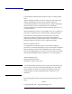
Introducing the 87130A Attenuator/Switch Driver Unpacking Your Instrument Unpacking Your Instrument Unpack and inspect the shipping container and its contents thoroughly to ensure that nothing was damaged during shipment. If the shipping container or cushioning material is damaged, the contents should be checked both mechanically and electrically.
Introducing the 87130A Attenuator/Switch Driver Unpacking Your Instrument Figure 1-3 Packaging Materials for the 87130A Switch Driver Item Quantity Part Number 1 1 9211-6365 Outer carton 2 1 5181-5515 Foam Insert 3 4 Description Foam insert (Part of item 2.
Introducing the 87130A Attenuator/Switch Driver Before Installing the Attenuator/Switch Driver Before Installing the Attenuator/Switch Driver Electrostatic discharge (ESD) can damage or destroy electronic components. All work performed on assemblies consisting of electronic components should be done at a static-safe workstation.
Introducing the 87130A Attenuator/Switch Driver Before Installing the Attenuator/Switch Driver Reducing ESD Damage To help reduce the amount of ESD damage that occurs during installation, testing, or servicing instruments use the following guidelines: Table 1-4 • Be sure that all instruments are properly earth-grounded to prevent buildup of static charge.
Introducing the 87130A Attenuator/Switch Driver Returning Your Instrument for Service Returning Your Instrument for Service To obtain servicing information or to order replacement parts, contact your nearest Agilent Technologies Service Center listed under “Service and Support” on page v. Use the following procedure to return your instrument to Agilent for service: 1. Fill out a service tag and attach it to the instrument. Please be as specific as possible about the nature of the problem.
Installing the 87130A Attenuator/Switch Driver 2 Installing the 87130A Attenuator/Switch Driver Overview In this chapter you will learn about: • • • • How to install your switch driver How to verify its basic functionality How to address your instrument How to connect it to a switch matrix Agilent 87130A Operating and Service Manual 2-1
Installing the 87130A Attenuator/Switch Driver Getting Started Getting Started Initial Inspection Preparing for Use 1. Unpack and inspect the shipping container and its contents thoroughly to ensure that nothing was damaged during shipment. If the shipping container or cushioning material is damaged, the contents should be checked both mechanically and electrically. A procedure for checking the electrical performance is given in Chapter 4, Verification.
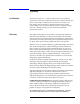
Installing the 87130A Attenuator/Switch Driver Getting Started GPIB Addressing Figure 2-1 3. Use the five-bit binary address switches located on the rear panel of the instrument to change the GPIB address. ❍ The 87130A has a factory preset address of 9. There are 32 possible addresses. The switch labeled with a one is the least significant bit. ❍ Addresses 0 and 31 are typically reserved for GPIB functions and should not be used. IEEE-488.
Installing the 87130A Attenuator/Switch Driver Connecting Switch Drivers to Switches and Attenuators Connecting Switch Drivers to Switches and Attenuators Driver Boards The standard 87130A attenuator/switch driver has a single internal driver board capable of driving 31 switches. The attenuator/switch driver may also be connected to a maximum of seven external 84940A driver board which can control and sense switching states for up to 217 additional switches.
Installing the 87130A Attenuator/Switch Driver Connecting Switch Drivers to Switches and Attenuators Using External Drivers Figure 2-3 A standard switch driver can control up to seven external 84940A driver cards. ❍ Each driver card has 31 4-pin black output connectors numbered J1 to J31 (silkscreened on the circuit side of the PCA) which connect to relays. ❍ Each relay is referred to as a channel by the switch driver.
Installing the 87130A Attenuator/Switch Driver Connecting Switch Drivers to Switches and Attenuators Do not connect or disconnect relays from 84940A external driver cards with prefixes prior to US4016 while the attenuator/switch driver line switch is turned on. An unintentional short between the + 24 V wire and the driver outputs may result in a catastrophic driver board failure.
Installing the 87130A Attenuator/Switch Driver Connecting Switch Drivers to Switches and Attenuators Wiring Channel Connectors Figure 2-6 When installing the switch driver, it is imperative to know which wires will cause an OPEN or CLOSE condition on each switch. • An OPEN condition is defined as the black wire from J1 pin 1 is active-to-common (+ 24 Vdc red wire). • A CLOSE condition is defined as the white wire from J1 pin 3 is active-to-common (+ 24 Vdc red wire).
Installing the 87130A Attenuator/Switch Driver Connecting Switch Drivers to Switches and Attenuators Connecting Multiple Driver Cards The cards are numbered from 1 to 8; the relays on each card are numbered from 0 to 30. Each relay is referred to as a channel by the switch driver. Therefore, there are a total of 248 relays (channels) that can be driven from a single switch driver.
Installing the 87130A Attenuator/Switch Driver Connecting Switch Drivers to Switches and Attenuators Connecting Attenuators Connect attenuator cables using a Viking connector and a ten pin connector. A typical connection of four section attenuators is shown below. When connecting attenuators • • Figure 2-9 A CLOSE position should add attenuation. An OPEN position should remove attenuation.
Installing the 87130A Attenuator/Switch Driver Connecting Switch Drivers to Switches and Attenuators Optimizing Switching Speed To increase the speed at which your switch matrix operates, refer to the table below to determine which four relays, when connected, will be on the same drive lines. a. Refer to Figure 2-6 to wire your relays into the arbitrary positions of OPEN and CLOSE. b.
Installing the 87130A Attenuator/Switch Driver Connecting Switch Drivers to Switches and Attenuators Driver Card Address Set the 4-bit DIP switch on the 84940A driver assembly card to each address as shown in the figure below. (S1 “up” is open or away from the PC board.) Each card must have a unique address setting. The internal driver is set to card 1. Card 1 shown below is the factory default setting.
Installing the 87130A Attenuator/Switch Driver Connecting Switch Drivers to Switches and Attenuators 70611-60011, and 70612-60011 cables of #28 AWG wire size, at a total cable length of 32.8 feet from the 87130A would have a voltage of 20.3 volts available at the driver board. (21.5 V - (750 mA X 0.065 ohms per foot X 32.8 feet X 0.75)).* This leaves 0.3 V that can be dropped in the wires from the board to the switches.
Installing the 87130A Attenuator/Switch Driver Connecting Switch Drivers to Switches and Attenuators Pin Functions for 36-Pin I/O Data Cable Table 2-2 • The standard switch driver has a high density male, 36-pin SCSI II type connector. • The standard I/O data cable is a five-foot 28 AWG cable with two female, 36-pin SCSI II type connectors.
Installing the 87130A Attenuator/Switch Driver Connecting Switch Drivers to Switches and Attenuators Pin Functions for 68-pin Driver Output Connector Table 2-3 • The 87130A has a rear-panel 68-pin connector for driving attached switches. The standard output cable is a six-foot 28 AWG cable with two male 68-pin SCSI II type connectors. • When you wire the switch driver to the switches, use the following table to define an OPEN or CLOSE position.
3 Specifications Overview Performance specifications are the performance standards or limits against which the 87130A can be tested. The specifications are organized into two categories: • Measurement related specifications which describe warranted performance for the 87130A over the temperature range of 0 to + 55 °C after one hour of continuous operation, unless otherwise noted. • Characteristics which provide useful (typical) but non-warranted functional and performance information for the 87130A.
Specifications Performance Specifications Performance Specifications Table 3-1 87130A Electrical Specifications Electrical Specifications Drive Capacity - 87130A 248 relays, when mated with seven external 84940A daisy chained driver cards. Each 84940A can drive up to 31 relays. The equivalent of one 84940A driver card is installed within the 87130A. Voltage + 24 + 3.0 / − 1.
Specifications Performance Specifications Table 3-2 87130A Environmental Specifications Environmental Specifications Temperature Operating 0 to + 55 °C Non-operating − 40 to 70 °C Humidity Operating and Non-operating 80% relative humidity up to 31 °C decreasing linearly to 50% relative humidity at 40 °C Altitude Operating and non-operating Environmental Compatibility 5600 meters (15,000 feet) Radiated and conducted emission is in compliance with CISPR Pub 11/1990, Group 1, Level A Environmental Q
Specifications Performance Specifications 3-4 Agilent 87130A Operating and Service Manual
4 Remote Operation Overview In this chapter you will learn about programming the 87130A using a controller: • How to set up the switch driver and start programming groups and paths for switches • • • • How to set switch delay, pulse width, and sensing How to sense switch status How to store and retrieve switch parameters via remote interface How to perform more complicated tasks using a combination of these four basic functions You will also find: • • • • A command tree of SCPI commands An alphabe
Remote Operation Programming Programming Standard Commands The instrument command language is Standard Commands for Programmable Instruments (SCPI). The programming examples and information in this chapter use the SCPI format. SCPI follows IEEE 488.2-1987 Codes, Formats, Protocols and Common Commands. Commands are sent over an GPIB bus which follows IEEE 488.1.
Remote Operation Programming Syntax Programming Syntax Talking to the Switch Driver In general, computers acting as controllers communicate with the switch driver by passing messages over a remote interface using the I/O statements provided in the instruction set of the controller’s host language. Therefore, the messages for programming the switch driver described in this manual, will normally appear as ASCII character strings imbedded inside the I/O statements of your controller’s program.
Remote Operation Programming Syntax Addressing the Switch Driver Since GPIB can address multiple devices through the same interface card, the device selector passed with the program message must include not only the correct interface code, but also the correct instrument address. Interface Select Code (Selects Interface) Each interface card has a unique interface select code. This code is used by the controller to direct commands and communications to the proper interface.
Remote Operation Programming Syntax Commands A command is composed of a header, any associated data, and a terminator. The header is the mnemonic or mnemonics that represent the operation to be performed by the switch driver. The different types of headers are discussed in the following paragraphs. Compound Command Header Compound command headers are a combination of two or more program mnemonics. The first mnemonic selects the subsystem, and the last mnemonic selects the function within that subsystem.
Remote Operation Programming Syntax Example *CLS is an example of a common command header. *CLS; ROUTE:DRIVE:ON (@100,102,104,106,....); Common commands used by the switch driver are explained in more detail in the “Common Command Reference” later in this chapter. Program Header Options Program headers can be sent using any combination of uppercase or lowercase ASCII characters.
Remote Operation Programming Syntax Character Program Data Character program data is used to convey parameter information as alpha or alphanumeric strings. Example ROUTE:VERIFY:ON:ALL The :VERIFY function is specified to be ON for ALL channels. Numeric Program Data Some command headers require program data to be a number. Example ROUTE:DELAY .03,(@101,103,105) where the :DELAY function is specified to be 30 ms on channels 101, 103, and 105.
Remote Operation Programming Syntax Query commands are also used to get results of switch status made by the switch driver, with the query actually activating the switch. Example ROUTe:CLOSE? instructs the driver to sense the status of the switch and place the result in the output queue. The output queue must be read before the next program message is sent.
Remote Operation Programming the Switch Driver Programming the Switch Driver Initialization To make sure the bus and all appropriate interfaces are in a known state, begin every program with an initialization statement. Example CLEAR 709 ! initializes the interface of the driver. Then initialize the switch driver to a preset state. For example: OUTPUT 709;“*RST” ! initializes the instrument to a preset state.
Remote Operation Programming the Switch Driver where GROUP1 represents the name of the desired group. This would enter the current label of the group in the string variable Setting$. Example All results for queries sent in a program message must be read before another program message is sent. When you send the query:ROUTe:CLOSE? (@101) you must follow that query with the program statement: ENTER 709;Sense$ to read the result of the query and place the result in a variable (SENSE$).
Remote Operation Programming the Switch Driver String Variables Example If you want to observe the headers for queries, you must bring the returned data into a BASIC string variable. Reading queries into string variables is simple and straightforward, requiring little attention to formatting. ENTER 709;Result$ places the output of the query in the string variable Result$. The output of the switch driver may be either numeric or character data depending on what is queried.
Remote Operation Common Commands Reference Common Commands Reference The common commands used in this instrument are shown in the following table. Table 4-1 • The common commands control some of the basic instrument functions, such as instrument identification and reset and how status is read and cleared. • The common commands are defined by the IEEE 488.2 standard and are common to all instruments that comply with this standard. IEEE 488.
Remote Operation *CLS (Clear Status) *CLS (Clear Status) Syntax *CLS Description The *CLS (clear status) common command clears the status data structures, including the device defined error queue. This command also clears *OPC and *OPC?. If the *CLS command immediately follows a PROGRAM MESSAGE TERMINATOR, the output queue and the MAV bit will be cleared.
Remote Operation *ESE (Event Status Enable) *ESE (Event Status Enable) Syntax *ESE mask *ESE? Description The *ESE command sets the Standard Event Status Enable Register bits. This register contains a mask value for the bits to be enabled in the Standard Event Status Register. A one in the Standard Event Status Enable Register will enable the corresponding bit in the Standard Event Status Register; a zero will disable the bit.
Remote Operation *ESR? (Event Status Register Query) *ESR? (Event Status Register Query) Syntax *ESR? Description The *ESR query returns the contents of the Standard Event Status Register. The table shows each bit in the Event Status Register and the bit weight. When you read the Event Status Register, the value returned is the total bit weights of all bits that are high at the time you read the byte. The register is cleared to 0 on a *CLS and after *ESR? is executed.
Remote Operation *IDN (Identification Number) *IDN (Identification Number) Syntax *IDN? Description The *IDN query allows the instrument to identify itself. It returns a string such as: HEWLETT-PACKARD,87130A,US12345678,950713 Where 950713 is the firmware version number and US12345678 is the serial number.
Remote Operation *OPC (Operation Complete) *OPC (Operation Complete) Syntax *OPC *OPC? Description The *OPC and *OPC? commands are used to synchronize remote interface software to internal module events. • • • The *OPC (operation complete) command will cause the instrument to set the operation complete bit in the Standard Event Status Register when any switching operations that were in process at the time the *OPC command was received have completed.
Remote Operation *RST (Reset) *RST (Reset) Syntax *RST Description *RST is equivalent to a power up condition for the switch hardware. All relays for which DRIVE is ON are set to the positions determined by ROUTe:PFAil. For any relays not in either the ROUTe:PFAil:OPEN or ROUTe:PFAil:CLOSE list, the positions which are stored in the “last state” list in RAM are used to set the initial switch position.
Remote Operation *SRE (Request Enable) *SRE (Request Enable) Syntax *SRE mask *SRE? Description The *SRE command sets the Service Request Enable Register bits. This will indicate whether or not the device has at least one reason for requesting service. A one in the Service Request Enable Register will enable the corresponding bit in the Status Byte Register; a zero will disable the bit. Refer to the table below for the bits in the Service Request Enable Register and what they mask.
Remote Operation *STB (Status Byte) *STB (Status Byte) Syntax *STB? Description The *STB query returns the current value of the instrument’s status byte. Refer to the table below for the definitions of the bits in the status byte.
Remote Operation *TST? (Test) *TST? (Test) Syntax *TST? Description *TST? causes all relays to cycle through both of their positions (first all the CLOSE paths are set; then all the OPEN paths), and then get placed in the appropriate power up positions. Refer to *RST (Reset) on page 4-18. All relays for which sensing is enabled (VERIFY:ON) are checked for proper operation each time they are switched. Unused relays (DRIVE:OFF) are neither switched nor checked.
Remote Operation *WAI *WAI Syntax *WAI Description The *WAI command causes the instrument to wait for all pending GPIB operations to finish before processing any further commands.
Remote Operation Hierarchy Hierarchy Table 4-6 Command Tree ROUTE :CLOSe :OPEN :PATH :DEFine :CATalog :LABel :VALue :DELete :ALL :GROUP :NAME :CATalog :ADD :REMove :DEFine? :LABel :AUTOselect :ON :OFF :DELete :DELete :ALL Agilent 87130A Operating and Service Manual 4-23
Remote Operation Hierarchy Table 6-6.
Remote Operation Hierarchy Table 6-6. Command Tree (continued) MEMory :DELete :INITialize :SAVE :FREE? STATus :OPERation :[EVENt]? :CONDition? :ENABle[?] :PTRansition :NTRansition :QUEStionable :[EVENt]? :CONDition? :ENABLe[?] SYSTem :VERSion? :ERRor? TRIGger :SEQuence :DELay[?] NOTE A colon ( : ) must be used in front of the ROUTE, DIAGnostics, MEMory, etc. commands if that command is not the first item in a command string. (The colon is optional if the command is the first in the string.
Remote Operation SCPI Command Reference SCPI Command Reference Channel Lists The 87130A can control up to seven different external driver cards, each of which can drive up to 31 different relays. The cards are numbered from 1 to 8; the relays on each card are numbered from 0 to 30. Each relay is referred to as a channel by the switch driver. Therefore, there are a total of 248 relays (channels) that can be driven from a single switch driver.
Remote Operation :ADD :ADD Syntax ROUTE:GROUP:ADD , Description This command adds an existing path to the end of an existing group. The group name and path name must have been previously defined using GROUP:NAME and PATH:DEF. A path may be added to a group in several places by issuing this command several times. Only one path can be added for each issuance of ADD. Example Command ROUTE:GROUP:ADD ATTEN,ATTEN_14; A previously defined path ATTEN_14 is added to group ATTEN.
Remote Operation :AUTOselect :AUTOselect Syntax [:ON] ROUTe:GROUP:AUTOselect[?] :OFF Description This turns the current Auto Select state for the group on or off. Example Command ROUTE:GROUP:AUTO:ON ATTEN; This turns the current Auto Select state for the group ATTEN on. ROUTE:GROUP:AUTO:OFF ATTEN; This turns the current Auto Select state for the group ATTEN off.
Remote Operation :CATalog? :CATalog? Syntax :PATH ROUTe :CATALOG? :GROUP Description Returns a list of groups (up to 16) or all defined paths in the module. Example Query ROUTE:GROUP:CATALOG? This query returns a list of all of the group names, in order from 1 to 16, separated by commas. ROUTE:PATH:CATALOG? This query returns a list of all the defined paths in the module, separated by commas.
Remote Operation :CLOSe :CLOSe Syntax ROUTe:CLOSe ROUTe:PFail:CLOSe[?] Description Each channel has a CLOSE or OPEN position. On Agilent relays, the CLOSE path is the path between the input terminal labeled 2 on the relay and the input terminal labeled C. It is recognized that CLOSE and OPEN are arbitrary for this type of switch; they are, however, in keeping with the SCPI language specification.
Remote Operation :CLOSe Example Command ROUTE:CLOSE ATTEN_14; Sending the above command causes the set of switch OPENs and CLOSEs defined by the PATH (refer to :PATH on page 4-55) with name ATTEN_14 to be executed. The first group of switch settings in the PATH is interpreted as CLOSE settings and the second group as OPEN settings. The ΧΛΟΣΕ settings are all executed first, followed by the OPEN settings.
Remote Operation :CLOSe Example Query ROUTE:PFAIL:CLOSE? (@101,205); The inclusion of a question mark causes a readback of the power up state of the requested channels as a list of 1’s and 0’s separated by commas. A 1 means the channel is in the PFA:CLOS list. A 0 means that it is not. • When querying the PFAil state, the PFA:OPEN list must be checked as well to determine whether the power up state for a given channel is programmed at all.
Remote Operation :CYCLes? :CYCLes? Syntax DIAGnostics:EERom:CYCLes? Description This query causes the 87130A to read back the number of times to which the EEROM has been written. If this number exceeds 10,000 the EEROM should be replaced. If the EEROM has never been written to, then 0 is returned.
Remote Operation :DEFine :DEFine Syntax ROUTe:PATH:DEFine , [,] ROUTe:GROUP:DEFine? ROUTe:PATH:DEFine? Description Under the PATH subsystem, this command is used to define or redefine the switch settings that make up a path. • This command effectively “creates” a path by assigning the path name to one of the 256 internal path registers (if no register is available, a memory error will be declared).
Remote Operation :DEFine Example Command ROUTE:PATH:DEF ATTEN_14,(@101,2(0:5)),(@102); This command defines a path whose name is ATTEN_14 whose first channel list affects channel 1 on card 1 and channels 0 through 5 on card 2, and whose second channel list affects channel 2 on card 1. Example Query ROUTE:PATH:DEFine? ATTEN_14; The query form returns a path description as two channel lists separated by a comma. It can be sent back by appending it to a PATH:DEF command to recreate the path.
Remote Operation :DELay :DELay Syntax ROUTe:DELay:, Description This commands sets the delay time in seconds required to validate the sense lines on a relay for which sensing will be used. The drive signal will be held on the relay for this amount of time after the pulse width requirement (refer to :WIDTh on page 4-67) has been satisfied. The delay time may be set in 5 ms increments up to 1275 ms. The delay time defaults to 20 ms when memory is initialized.
Remote Operation :DELay NOTE The query form is not available when using a path name due to the potential for confusion between the first group and the second in the path.
Remote Operation :DELete :DELete Syntax :PATH ROUTE :DELete :GROUP [:ALL] Description This command deletes: • All data associated with the specified path or group and frees up the path storage register. • All channels from the PFAIL list. This command sets memory to an initial state. NOTE The :DELete and the :DELay shortform is the same.
Remote Operation :DELete • MEMory:DELete; erases all data from CMOS RAM, by filling it with zeroes, and then sets it to an initial state. That state is as follows: MEMory:DELete ❍ The power fail channel lists are empty (ROUT:PFA:CLOS and ROUT:PFA:OPEN). ❍ Sensing (VERIFY) is OFF for all devices. ❍ The ROUT:DRIVE:ON list has channels 0 through 30 on card 1 used and all other channels unused. ❍ The WIDTH is set to 30 ms pulse width; DELAY is set to 20 ms for all 256 devices.
Remote Operation :DRIVe :DRIVe Syntax [:ON] ROUTe:DRIVe :OFF : ALL [:ON] ROUTe:DRIVe [?] :OFF [:ON] ROUTe:DRIVe :OFF : Description There is a list of relays considered unused or “not there” by the firmware. Unused channels are not driven even if included in a channel list or path and are not checked for proper sense line state and cannot generate errors. Turning :DRIVE:OFF for a channel adds it to the Unused List.
Remote Operation :DRIVe Example Query • ROUTE:DRIVE:ON? (@101,103,105); This command returns a list of 1’s and 0’s, separated by commas, depending on whether drive is on or off for the indicated channels. If it is on for channels 101 and 105 and off for 103, the switch driver will return: 1,0,1 • ROUTE:DRIVE:OFF? (@101,103,105) This command returns a list of 1’s and 0’s, separated by commas, depending on whether drive is on or off for the indicated channels.
Remote Operation :EERom :EERom Syntax DIAGnostics:EERom:CYCLes? Description This function allows EERom information to be read out. (Refer to :CYCLes? on page 4-33.
Remote Operation :ERRor? :ERRor? Syntax SYSTem:ERRor? Description As SCPI specifies, this reads out the full error number and error description for the first error in the error queue. It can be issued repeatedly until the queue is empty (indicated by 0,”No error”). All possible error numbers with their descriptions are listed below. Command Errors These set the Cmd Err bit in ESR.
Remote Operation :ERRor? -181,Invalid outside macro definition -183,Invalid inside macro definition Execution Errors These set the Exec Err bit in ESR. -200,Execution error -222,Data out of range -223,Too much data -270,Macro error -272,Macro execution error -273,Illegal macro label -276,Macro recursion error -277,Macro redefinition not allowed Device Specific Errors These set the Cmd Err bit in ESR.
Remote Operation :ERRor? 1004,EEROM data invalid Corruption has been detected in the EEROM; it needs to be replaced, or, if brand new, it needs to have MEM:SAVE executed once. 1006,Channel timeout <17 hex digits> This error is generated when a relay apparently fails to switch, based on the detected state of the sense lines. The 17 hex digits indicate which card and which of the 32 channels experienced failures just as for error 1001.
Remote Operation :FREE? :FREE? Syntax MEMory:Free? Description This is a query which returns the number of bytes that remain in RAM for storing configuration data, followed by the number of bytes initially available. The two quantities are separated by commas. For a brand new system there are around 13,000 bytes initially available.
Remote Operation :GROUP :GROUP Syntax ROUTE: GROUP: :NAME :CATALOG? :ADD[?] :REMOVE[?] :DEFine[?] :LABEL[?] :AUTOselect[?] :DELete [ :ALL ] Description The GROUP subsystem allows grouping of paths to customize the manual interface to the 87130A. A “group” is an ordered collection of up to 256 paths. Paths can be collected into meaningful groups using the GROUP command. The 87130A can store up to 16 groups. Each group may be defined and labeled.
Remote Operation :INITialize :INITialize Syntax MEMory:INITialize Description When this command is issued, RAM is initialized according to the following algorithm: 1. RAM is initialized to the state described in MEMory:DELete. This command essentially erases any changes that have been made to RAM since the last power cycle. 2. The model number is initialized to 87130A. The serial number is initialized to USXXXXXXXX.
Remote Operation :LABel[?] :LABel[?] Syntax ROUTe :PATH :LABEL “
Remote Operation MEMory MEMory Syntax :DELete :INITialize MEMory :SAVE :FREE? Description The MEMory subsystem is used to delete, initialize RAM, and save EEROM information to the controller.
Remote Operation :NAME :NAME Syntax ROUTE:GROUP:NAME , Description The groups are numbered from 1 to 16. They may be named or renamed using this command. An attempt to name a group using a name already in use for another group will result in an error. A group name is any collection of up to 12 uppercase letters (lowercase letters are automatically uppercased), numbers, or underscore characters, starting with a letter.
Remote Operation :OPEN :OPEN Syntax ROUTe:OPEN[?] ROUTe:PFail:OPEN[?] Description Each channel has a CLOSE or OPEN position. On Agilent relays, the OPEN path is the path between the input terminal labeled 1 on the relay and the input terminal labeled C. It is recognized that CLOSE and OPEN are arbitrary for this type of switch; they are, however, in keeping with the SCPI language specification.
Remote Operation :OPEN It is possible to combine OPEN and CLOSE in a single command since they are both part of the ROUTe subsystem. For example: ROUTE:CLOSE (@406:410);OPEN (@202); This command will close channels 6 through 10 on card 4 and open channel 2 on card 2. Example Command ROUTE:OPEN ATTEN_14; Sending the above command causes the set of switch OPENs and CLOSEs defined by the PATH with name ATTEN_14 to be executed.
Remote Operation :OPEN Example Query ROUTE:PFAil:OPEN? (@101,205); The inclusion of a question mark causes a readback of the power up state of the requested channels as a list of 1s and 0s separated by commas. ❍ A 1 means the channel is in the PFA:OPEN list. ❍ A 0 means that it is not. When querying the PFAIL state, the PFA:CLOS list must be checked as well to determine whether the power up state for a given channel is programmed at all.
Remote Operation :PATH :PATH Syntax ROUTe:PATH :DEFine[?] :CATalog? :LABel[?] :VALue[?] :DELete[:ALL] Description The PATH subsystem allows storing of channel lists to simplify remote access and to customize the manual interface to the 87130A. NOTE • Paths are specified using CLOSE and OPEN channel lists. Each relay contains one CLOSE and one OPEN path. Refer to the command explanations :CLOSe on page 4-30 and :OPEN on page 4-52 for more information.
Remote Operation :PFAil :PFAil Syntax :CLOSe ROUTe:PFAil :OPEN :DELete Description The ROUTe:PFAil subsystem of SCPI allows specification of which channels will be closed on a power cycle (or *RST or *TST?). NOTE • Channels not specified by ROUTE:PFAIL:CLOSE or ROUTE:PFAIL:OPEN are set during power up by reading the last switch state out of EEROM or CMOS RAM, or if the EEROM data is corrupt, by OPENing the channel.
Remote Operation :REMove :REMove Syntax ROUTe:GROUP:REMove , Description This command removes all instances of the specified path from a group. The group name and path name must have been previously defined using GROUP:NAME and PATH:DEF. Example Command ROUTE:GROUP:REMOVE ATTEN,ATTEN_14; Removes all paths named ATTEN_14 from group ATTEN. Refer to the query :DEFine? to list all paths in a group.
Remote Operation ROUTe ROUTe Syntax Refer to the command tree. Description Relay switching and configuration is accomplished by the ROUTe command tree.
Remote Operation :SAVE :SAVE Syntax MEMory:SAVE Description This command copies the RAM image to the EEROM. Care should be taken to do this only when necessary, due to the limited life of the EEROM. (Refer to DIAG:EEROM:CYCLES?). Because this is time consuming (over a minute in some cases), it is made to turn on the “switching” light while saving. The CALIBRATING bit in the OPER status register is set when a save begins and cleared when it ends. *OPC can also be used to detect the end of a save.
Remote Operation STATus STATus Syntax :[EVENt]? :CONDition STATus:OPERation :ENABle[?] :PTRansition :NTRansition[?] STATus:QUEStionable :[EVENt]? :CONDition? :ENABle[?] Description The STATus subsystem is fully specified by SCPI.
Remote Operation SYSTem SYSTem Syntax :VERSion? SYSTEM :ERRor? Description These are SYSTem commands from the SCPI specification.
Remote Operation TRIGger TRIGger Syntax TRIGger:SEQuence:DELay Description This command allows the user to control the 24 V power supply recovery time. Input values are limited to between 0 and 200 msec (200 msec is the default setting). The GPIB command TRIGger:SEQuence:DELay will allow entry of a new power recovery time. Values outside the 0 to 200 msec range will return an error. Example Command TRIG:SEQ:DEL .15 This example assigns the value, 150 msec, to the TRIGger command.
Remote Operation :VALue :VALue Syntax ROUTe:PATH:VALUE ,; Description This command specifies a number (integer in the range – 32768 to 32767) to be used when labeling the path on manual interface screens. This number, when entered manually from the user interface, can be used to select paths directly without using the RPG or step keys. Example Command ROUTE:PATH:VALUE ATTEN_14,14; This example assigns a value of 14 to a path with pathname ATTEN_14.
Remote Operation :VERify :VERify Syntax :ALL :[ON} ROUTe:VERify OFF :[ON} ROUTe:VERify [?] OFF Description This command adds or removes relays from the “sense list”, the list of relays for which sensing is enabled. This command only works with relays that have the ability to sense the state of the switch. Refer to the list of Agilent compatible switches and attenuators that have this capability.
Remote Operation :VERify ROUTE:VERIFY:ON ATTEN_14; This command causes the set of switches defined by the PATH with the pathname ATTEN_14 to be added to (ON) or removed from (OFF) the "sense list. All switches referenced in either channel list in the path are added (ON) or removed (OFF). ROUTE:VERIFY:OFF:ALL; This turns sensing off for all channels.
Remote Operation :VERsion? :VERsion? Syntax SYSTem:VERSion? Description This reads out the firmware datecode.
Remote Operation :WIDTh :WIDTh Syntax ROUTe:WIDTh , ROUTe:WIDTh Description This command sets the pulse width in seconds required to close a relay. The pulse width may be set in 5 ms increments up to 1275 ms. The pulse width defaults to 30 ms when memory is initialized. The WIDTh parameter may be an integer or a real number. Example Command ROUTE:WIDTH .
Remote Operation Example Programs Example Programs The following programs written in Rocky Mountain Basic provide sample programs that may be helpful in programming the 87130A. Save Memory In order to use the following program, you must first create a file named SWDATA. The following program can be used to read configuration data out of the EEROM so that it can be replaced. 10 ! READMEM program.
Remote Operation Example Programs 280 ENTER @Sw;A$ 290 I=-1 300 WHILE LEN(A$)>0 310 Comma=POS(A$,”,”) 320 IF Comma=0 THEN 330 A$=A$&”,” 340 Comma=LEN(A$) 350 END IF 360 I=I+1 370 Groupnames$(I)=A$[1;Comma-1] 380 A$=A$[Comma+1] 390 END WHILE 400 OUTPUT @File;Groupnames$(*) 410 Max_group=I 420 FOR G=0 TO Max_group 430 OUTPUT @Sw;”ROUT:GROUP:LABEL? “&Groupnames$(G) 440 ENTER @Sw;Grouptitles$(G) 450 OUTPUT @Sw;”ROUT:GROUP:AUTOSELECT:ON? “&Groupnames$(G) 460 ENTER @Sw;Groupa
Remote Operation Example Programs 670 WHILE LEN(A$)>0 680 Comma=POS(A$,”,”) 690 IF Comma=0 THEN 700 A$=A$&”,” 710 Comma=LEN(A$) 720 END IF 730 I=I+1 740 Pathnames$(I)=A$[1;Comma-1] 750 A$=A$[Comma+1] 760 END WHILE 770 OUTPUT @File;Pathnames$(*) 780 Max_path=I 790 FOR P=0 TO Max_path 800 OUTPUT @Sw;”ROUT:PATH:LABEL? “&Pathnames$(P) 810 ENTER @Sw;Pathtitles$(P) 820 OUTPUT @Sw;”ROUT:PATH:VALUE? “&Pathnames$(P) 830 ENTER @Sw;Pathval(P) 840 OUTPUT @Sw;”ROUT:PATH:DEF? “&Pathnam
Remote Operation Example Programs Restore Memory The following program can be used to restore the EEROM state read out by READMEM: 10 ! WRITEMEM program. Takes a file written by READMEM and sends it to the 87130A.
Remote Operation Example Programs 330 ENTER @File;Pathnames$(*) 340 FOR I=0 TO 255 350 360 370 380 send path data IF Pathnames$(I)<>”” THEN ENTER @File;A$ OUTPUT@Sw;”ROUT:PATH:DEF”&Pathnames$(I)&”,”&A$&”;” END IF 390 NEXT I 400 FOR I=0 TO 15 410 ! ! send group data IF Gpnames$(I)<>”” THEN 420 OUTPUT @Sw;”ROUT:GROUP:NAME”&VAL$(I+1)&”,”&Gpnames$(I)&”;” 430 IF Groupauto(I) THEN 440 450 460 OUTPUT @Sw;”ROUT:GROUP:AUTOSELECT:ON “&Gpnames$(I)&”;” ELSE OUTPUT @Sw;”ROUT:GROUP:AUTOSELECT:OFF” &
Remote Operation Example Programs 650 END 660 SUB Getandsend_bmap(B$) 670 ! Loads a query response from file and outputs it as a channel list 680 COM @File,@Sw 690 DIM Bitmap(7,31),A$[32767] 700 ENTER @File;Bitmap(*) 710 FOR I=0 TO 7 720 A$=”” 730 FOR J=0 TO 31 740 IF Bitmap(I,J) THEN A$=A$&”,”&VAL$(100*(I+1)+J) 750 NEXT J 760 IF A$[1;1]=”,” THEN A$=A$[2] 770 IF A$<>”” THEN OUTPUT @Sw;B$&” (@”&A$&”);” 780 NEXT I 790 SUBEND 800 SUB Getandcalc_bmap(B$) 810 ! Loads a query res
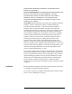
Remote Operation Example Speed Calculation Example Speed Calculation Switching speed is a function of pulse widths, sensing delays, the state of the chosen channels, the sequence of relays driven and the power suply recovery time. A sample program and timing diagram are provided to help the user minimize switching time, since the user determines pulse widths, sensing delays and which channels are opened or closed. Table 4-7 shows which connectors (J1 to J31) are on the same drive lines.
Remote Operation Example Speed Calculation 60 ! a range. 70 OUTPUT 709;”ROUT:DRIV:OFF (@112:130);” 80 ! 90 ! Drive is set to OFF for remaining channels on driver 100 ! card 1.Unless channels are part of Drive list, no 110 ! pulse (:WIDTh) is sent. 120 OUTPUT 709;”ROUT:VER:ON (@100:111);” 130 ! 140 ! Sensing is ON for channels 100 through 111. 150 ! VERify:ON works at switching time, and errors 160 ! (if they exists) are reported back immediately.
Remote Operation Example Speed Calculation 380 OUTPUT 709;”ROUT:WIDT .04,(@100,102,104,108);” 390 ! 400 ! Pulse (:WIDTh) is set to 40 ms for channels 100,102, 410 ! 104, and 108. When :OPEN is sent, 100 and 102 420 ! will OPEN at the same time. 430 ! Channels 104 and 108 will each OPEN at different 440 ! times, because they are connected to different 450 ! drive lines. See the Relay Drive Sequence table 460 ! and Figure 6-1, Timing Diagram.
Remote Operation Example Speed Calculation 780 ! See timing chart to predict when each relay will 790 ! open. 800 OUTPUT 709;”ROUT:OPEN? (@100:104,108:111);” 810 ! 820 ! You turned sensing off for 104 thru 107, remember? 830 ! About OPEN?: you could still query for the entire 840 ! open list for channels 100 to 111. Channels 104 to 850 ! 107 would still report back 1,1,1,1. 860 ! The query :OPEN? (or :CLOSe?) queries the channel 870 ! list, not the relay.
Remote Operation Example Speed Calculation 4-78 Agilent 87130A Operating and Service Manual
5 Replaceable Parts Overview In this chapter you will find: • Accessories available for the switch driver by part number and description. • All replaceable parts referenced in chassis and cable assemblies.
Replaceable Parts This page intentionally left blank 5-2 Agilent 87130A Operating and Service Manual
Replaceable Parts Accessory Boards and Cables Table 5-1 Firmware Revisions Additional driver boards, interconnect boards, and cables provide expanded capacity, remote switching and everything needed for device connection.
Replaceable Parts Table 5-2 Part Location Replaceable Parts - 87130A Chassis Assembly (1) Part Number Quantity Description Reference Designator 1 87130-00009 1 Deck — 2 87130-00011 1 Power supply shield — 3 87130-62065 1 Driver board A2 4 87130-00010 1 PC board bracket assembly — 5 87130-00008 1 Shield, bottom cover — 6 87130-60002 1 Controller board A1 7 87130-00007 1 Shield, top cover — 8 87130-00002 1 Front sub-panel — 9 87130-00001 1 Front dress panel —
Replaceable Parts Figure 5-1 87130A Chassis Assembly (1) Agilent 87130A Operating and Service Manual 5-5
Replaceable Parts Table 5-3 Replaceable Parts - 87130A Chassis Assembly (2) Part Location Part Number Quantity Description 1 5021-8401 1 Front frame 2 5021-5802 1 Rear frame 3 5021-5887 2 Side strut 4 5041-8802 1 Top trim 5 5063-9226 1 Front handle kit 6 5021-8495 2 Trim, front handle 7 5041-8801 4 Foot, bottom 8 5062-3776 2 Side cover 9 5062-3704 2 Strap handle 10 5041-8819 2 Front cap 11 5041-8820 2 Rear cap 12 5041-8821 4 Rear panel foot 13 5062-3747
Replaceable Parts Figure 5-2 87130A Chassis Assembly (2) Agilent 87130A Operating and Service Manual 5-7
Replaceable Parts Table 5-4 Replaceable Parts - 87130A Cable Assembly Part Location Part Number Quantity Description Reference Designator 1 87130-62065 1 Driver board A2 2 87130-60002 1 Controller board A1 3 0950-2252 1 Power supply 110 W A3 4 87130-60001 1 Display board A4 5 87130-60008 1 GPIB address board A5 3101-2325 1 GPIB address switch (part of GPIB address board) — 87130-60007 1 AC line cable assembly — 2110-0782 1 Fuse T 1A 250V UL/CSA (part of AC input modu
Replaceable Parts Figure 5-3 87130A Cable Assembly Agilent 87130A Operating and Service Manual 5-9
Replaceable Parts 5-10 Agilent 87130A Operating and Service Manual
6 Troubleshooting Overview In this chapter you will find: • • How to check the fuses and power supply How to set up the EPROM after replacement Agilent 87130A Operating and Service Manual 6-1
Troubleshooting Troubleshooting Troubleshooting If your instrument is still in warranty we strongly recommend that you send the entire unit back to Agilent Technologies for repair. A procedure for checking the fuses and power supply is given on page 6-4. WARNING • To avoid electrical shock, do not perform any servicing unless you are qualified to do so. • Disconnect the product from all voltage sources while it is being opened. The opening of covers or removal of parts may expose dangerous voltages.
Troubleshooting Troubleshooting Figure 6-1 87130A DC Schematic Agilent 87130A Operating and Service Manual 6-3
Troubleshooting Fuse and Power Supply Check Fuse and Power Supply Check Fuse Check If the attenuator/switch driver fails to respond when the power switch is turned on, the power line fuse should be checked. The 1 A, 250 V time delay, power line fuse (part number 2110-0782) is located inside the AC input module. You will have to remove the top cover of the instrument to check the power supply fuses.
Troubleshooting Procedure for Setting Up the EPROM Procedure for Setting Up the EPROM Use the following procedure to set up the EPROM after the EPROM or the CPU board has been replaced. • To set up the EPROM from the controller, use the following commands: "MEM:DEL; Deletes everything in CMOS RAM memory. "SYST:ERR?" READ GPIB FOR ERROR Check the error queue (this can be used at any point to read any error back). "DIAG:MOD ""87130A""," Writes model number of your instrument.
Troubleshooting Procedure for Setting Up the EPROM 6-6 Agilent 87130A Operating and Service Manual
Index A accessories, description, 5-13 ADD, 4-27 address channel, 2-4 driver card, 2-11 factory preset, 2-3 GPIB, 2-3 switch driver, 4-4 AUTOselect, 4-28 B block diagram, 1-2 boards, accessory, 5-13 C cable I/O data, 2-13 output, 2-14 cables, accessory, 5-13 CATalog, 4-29 channel address, 2-4 creating lists, 4-26 definition, 2-4 list empty, 4-34 character program data, 4-7 characteristics, 3-2 CLOSe, 4-30 CLOSE condition defined, 2-7 CLS, 4-13 command syntax, 4-5 common commands *CLS, 4-13 *ESE, 4-14 *ES
compound, 4-5 options, 4-6 I I/O data cable description, 2-13 pin functions, 2-13 IDN, 4-16 If, 6-2 initialization, 4-9 INITialize, 4-48 inspection, 2-2 installation, 2-1 instrument status, 4-11 interface seIect code, 4-4 cord, 2-2 requirements, 2-2 power supply test points, 6-4 program header options, 4-6 message syntax, 4-4 message terminator, 4-7 program data character, 4-7 numeric, 4-7 programming language, 4-2 standard commands, 4-2 syntax, 4-3 Q query command, 4-7 L LABel, 4-49 M MEMory, 4-50 mul
SAVE, 4-59 STATus, 4-60 SYSTem, 4-61 TRIGger, 4-62 VALue, 4-63 VERify, 4-64 VERsion, 4-66 WIDTh, 4-67 selecting multiple subsystems, 4-5 sensing delay, 1-3 serial number, 4-48 setting up the switch driver, 4-9 specifications environmental, 3-3 SRE, 4-19 STATus, 4-60 status registers, 4-11 STB, 4-20 string variables, 4-11 supplemental characteristics, 3-2 switch driver address, 4-4 initialization, 4-9 receiving information, 4-9 setup, 4-9 syntax command, 4-5 program message, 4-4 SYSTem, 4-61 T talking to th
Index-4 Agilent 87130A Operating and Service Manual