LAN Interface User’s Guide Supplement Agilent Technologies 8712ET/ES and 8714ET/ES RF Network Analyzers Part No.
Notice The information contained in this document is subject to change without notice. Agilent Technologies makes no warranty of any kind with regard to this material, including but not limited to, the implied warranties of merchantability and fitness for a particular purpose. Agilent Technologies shall not be liable for errors contained herein or for incidental or consequential damages in connection with the furnishing, performance, or use of this material.
Acknowledgments Excel™ is a product of Microsoft® Corporation. Lotus® 1-2-3®, and Lotus Amipro are U.S. registered trademarks of Lotus Development Corporation. Microsoft Excel® and Microsoft Word are U.S. registered trademarks of Microsoft Corporation. QuickBasic™ is a product of Microsoft Corporation. Windows® is a registered trademark of Microsoft Corporation. Portions of the TCP/IP software are copyright Phil Karn, KA9Q.
Documentation Outline This User’s Guide Supplement describes how to connect, use and troubleshoot the LAN interface on your analyzer. This supplement contains the following chapters: 1. Connecting and Configuring the Analyzer Describes how to connect the analyzer to the LAN, and how to configure the analyzer for use on the LAN. Basic user account and file administration is also described. To effectively use this chapter, you should be familiar with your network setup and operation. 2.
Agilent Technologies 8712ET/ES and 8714ET/ES Network Analyzer Documentation Map The CDROM provides the contents of all of the documents listed below. The User’s Guide shows how to make measurements, explains commonly-used features, and tells you how to get the most performance from the analyzer. The LAN Interface User’s Guide Supplement shows how to use a local area network (LAN) for programming and remote operation of the analyzer.
The Example Programs Guide provides a tutorial introduction using BASIC programming examples to demonstrate the remote operation of the analyzer. The Service Guide provides the information needed to adjust, troubleshoot, repair, and verify analyzer conformance to published specifications. The HP Instrument BASIC User’s Handbook describes programming and interfacing techniques using HP Instrument BASIC, and includes a language reference.
Contents 1. Connecting and Configuring the Analyzer About This Chapter . . . . . . . . . . . . . . . . . . . . . . . . . . . . . . . . . . . . . . . . . 1-2 Intoducing the LAN Interface . . . . . . . . . . . . . . . . . . . . . . . . . . . . . . . . . 1-3 LAN Client/Server Functions . . . . . . . . . . . . . . . . . . . . . . . . . . . . . . . 1-4 Connecting the Analyzer to the LAN . . . . . . . . . . . . . . . . . . . . . . . . . . . 1-5 Setting Up a Network . . . . . . . . . . . . . . . . . . . . . . . .
Contents Windows LAN Wizard. . . . . . . . . . . . . . . . . . . . . . . . . . . . . . . . . . . . .1-21 2. Accessing the Analyzer's Web Pages About This Chapter . . . . . . . . . . . . . . . . . . . . . . . . . . . . . . . . . . . . . . . . .2-3 Accessing the Analyzer with Your Web Browser . . . . . . . . . . . . . . . . . .2-4 Screen Snapshot . . . . . . . . . . . . . . . . . . . . . . . . . . . . . . . . . . . . . . . . . .2-6 Control the Analyzer with SCPI Commands. . . . . . . . . . . . . . . . . . .
Contents 5. Accessing the Analyzer's Dynamic Data Disk The Dynamic Data Disk . . . . . . . . . . . . . . . . . . . . . . . . . . . . . . . . . . . . . 5-2 Saving and Recalling Analyzer States . . . . . . . . . . . . . . . . . . . . . . . . . . 5-5 Copying Programs to and from the Analyzer. . . . . . . . . . . . . . . . . . . . . 5-7 Copying an IBASIC Program to or from the Analyzer . . . . . . . . . . . . 5-7 Copying and Running a Program with One Command . . . . . . . . . . .
Contents Collecting SICL LAN Setup Information. . . . . . . . . . . . . . . . . . . . . .6-43 Configuring Your Analyzer as a SICL LAN Server. . . . . . . . . . . . . .6-44 Configuring Your PC as a SICL LAN Client . . . . . . . . . . . . . . . . . . .6-44 Controlling Your Analyzer with SICL LAN and HP VEE . . . . . . . .6-45 Controlling Your Analyzer with SICL LAN and HP BASIC for Windows . . . . . . . . . . . . . . . . . . . . . . . . . . . . . . . . . . . . . . . . . . . . . . .
Contents If you cannot connect to the analyzer . . . . . . . . . . . . . . . . . . . . . . . . 8-18 If you cannot access the file system via ftp . . . . . . . . . . . . . . . . . . . . 8-18 If you cannot telnet to the command parser port . . . . . . . . . . . . . . . 8-19 If you get an "operation timed-out" message . . . . . . . . . . . . . . . . . . 8-19 If you cannot access internal web pages or import graphic images when using a point-to-point connection . . . . . . . . . . . . . . . . . . . . . . . . .
1 Connecting and Configuring the Analyzer 1-1
Connecting and Configuring the Analyzer About This Chapter About This Chapter This chapter describes how to • connect your analyzer to your network • set up a network • configure your analyzer • verify connectivity • manage user names and passwords • configure your analyzer automatically using BOOTP • run programs automatically using BOOTP In order to complete the steps in this chapter, you'll need ❏ A computer with a LAN interface, running an operating system that supports TCP/IP, like UNIX® or Microsoft
Connecting and Configuring the Analyzer Intoducing the LAN Interface Intoducing the LAN Interface With the LAN interface you can • transfer IBASIC programs between your computer and your analyzer • transfer files between your computer and your analyzer using file transfer protocol (FTP) • save files from your analyzer to a computer using network file system (NFS) • connect many analyzers to one computer • automate the control of your analyzer • program the analyzer using SCPI commands • print
Connecting and Configuring the Analyzer Intoducing the LAN Interface LAN Client/Server Functions Your analyzer acts as either a client or server when you use the client/server features of the analyzer. For example, if you use Network File System (NFS), your analyzer acts as an NFS client (see Chapter 7, “Using the Network File System (NFS),” on page 7-1).
Connecting and Configuring the Analyzer Connecting the Analyzer to the LAN Connecting the Analyzer to the LAN Your analyzer has an RJ-45 connector (see Figure 1-1) and connects to your network using 10Base-T unshielded twisted pair (UTP) cabling, also called Ethertwist. Ethertwist cables resemble standard modular phone cables. NOTE If your network uses ThinLAN (10Base-2), you will need to purchase an adapter which converts the ThinLAN BNC connector to 10Base-T Ethertwist.
Connecting and Configuring the Analyzer Setting Up a Network Setting Up a Network If you do not already have a network, you will need to create one. A simple network consists of a central LAN hub with multiple Ethertwist cables, one connected to the LAN port of each network device. This is often called a star topology, with the LAN hub at the center.
Connecting and Configuring the Analyzer Setting Up a Network Point-to-Point Connections It is possible to connect a single computer to a single analyzer, and avoid using a LAN hub. To do this, you must use a special “cross-over” cable or adapter, which acts like a LAN hub. See “EIA/TIA 568B Wiring” on page 9-2 for wiring details. If you try to create a point-to-point connection using a standard “straight-through” cable, it will not work.
Connecting and Configuring the Analyzer Configuring the Analyzer Configuring the Analyzer Before you configure your analyzer, you will need to contact your network administrator to obtain the following information: ❏ an IP address for the analyzer ❏ a host name for the analyzer ❏ a gateway IP address ❏ a subnet mask The Analyzer's IP Address and Hostname Each device on your network must have a unique address so that all devices can communicate simultaneously over the same network.
Connecting and Configuring the Analyzer Configuring the Analyzer The Gateway Address If your analyzer will be communicating with devices on different physical networks, you may need to have your network administrator assign a gateway IP address for you. The gateway IP address is the address of a routing device that connects your analyzer's LAN with other LANs. Set the gateway address to 0.0.0.0 if a gateway is not required. See “To Configure the Analyzer” on page 1-10 to set this.
Connecting and Configuring the Analyzer Configuring the Analyzer To Configure the Analyzer 1. Press SYSTEM OPTIONS NOTE LAN to access the LAN menu. After each of the following steps, the analyzer will prompt you to cycle power for the new setting to take effect. It is not necessary to cycle the power after each step. It only needs to be done once—when you are finished entering all of the settings. 2.
Connecting and Configuring the Analyzer Testing the LAN Communication Testing the LAN Communication You should now test communication between your computer and your analyzer. The ping utility is typically used to test LAN communication.
Connecting and Configuring the Analyzer Testing the LAN Communication The following response is generally caused by an incorrect subnet mask or IP address. It usually points to a software setting conflict, and does not signify a hardware problem. Host Host Host Host Unreachable. Unreachable. Unreachable. Unreachable.
Connecting and Configuring the Analyzer Managing User Names and Passwords Managing User Names and Passwords Your analyzer implements a limited form of network security using user name and password pairs. Any remote access of the analyzer, including Telnet or FTP access, requires a valid user name and associated password.
Connecting and Configuring the Analyzer Managing User Names and Passwords 7. Type the password again (to confirm the password) in the displayed dialog box. 8. Press Enter when you are done. If the entries are valid, the new user name and password will be confirmed with the following message: User ... has been added to the list Removing a User from the Access List Perform the following steps to remove a user from the access list: 1. Press SYSTEM OPTIONS LAN Login User Setup . 2. Press Delete Login User .
Connecting and Configuring the Analyzer Using BOOTP Using BOOTP BOOTP Fundamentals The Bootstrap Protocol (BOOTP) is a simple and elegant method of automatically distributing network information and software via the LAN. BOOTP is built on the client-server model. The BOOTP client configures itself using configuration information obtained from a BOOTP server. Your analyzer has a built-in BOOTP client.
Connecting and Configuring the Analyzer Using BOOTP ❏ The Ethernet address of the analyzer. To find out the Ethernet address of your analyzer, press LAN LAN Port Setup SYSTEM OPTIONS Ethernet Address . ❏ An IP address for the analyzer. This address is usually assigned by your network administrator. ❏ An optional BOOTP host name and IP address. ❏ An optional absolute (fully qualified) path to the boot file, which includes all the directories leading to it.
Connecting and Configuring the Analyzer Using BOOTP a request. The analyzer will continue to retransmit requests at exponentially increasing time intervals until it receives a response or the Timeout value has expired. 5. Press Optional Boot Host and enter a hostname or a host IP address if you want BOOTP requests sent to a specific remote host only. Otherwise, the analyzer will broadcast a BOOTP request at boot time, and will accept a response from any BOOTP server.
Connecting and Configuring the Analyzer Using BOOTP NOTE Normally, your analyzer will obtain this file name from the BOOTP server, but you can override this using Optional File Name . If you do not want to use Optional File Name , make sure that it contains a null string. To do that, press Optional File Name Clear Entry Enter Etry You can set up your BOOTP server to select the file to download when the analyzer boots.
Connecting and Configuring the Analyzer Using BOOTP Figure 1-3 BOOTP Setup Dialog Box The dialog box shown above displays the following information: Host Addr the host address of the BOOTP server IP Addr the analyzer IP address set by BOOTP process Gateway the analyzer gateway IP address set by the BOOTP process Subnet Mask the subnet mask set for the analyzer by the BOOTP process File Path the absolute (fully-qualified) path name received from the BOOTP server, or the [Optional File Path] if set
Connecting and Configuring the Analyzer Using BOOTP 2. Clear your current network configuration information. LAN LAN Port Setup a. Press SYSTEM OPTIONS 871xxx IP Address Clear Entry Enter . 81xxx IP Address Etry LAN LAN Port Setup b. Press SYSTEM OPTIONS Gateway IP Address Clear Entry Enter . 81xxx IP Address Etry LAN LAN Port Setup c. Press SYSTEM OPTIONS Subnet Mask Clear Entry Enter . 81xxx IP Addre Etry 3.
Connecting and Configuring the Analyzer Setting Up LAN Features with Wizards Setting Up LAN Features with Wizards IBasic LAN Wizard An IBasic LAN wizard program is included with the analyzer to assist users in setting up the LAN features. It is located on the Example Program Disk, part number 08714-10003, under the name lan_wiz. Windows LAN Wizard A Windows-based LAN wizard program is also included with the analyzer to assist users in setting up the LAN features.
2 Accessing the Analyzer's Web Pages 2-1
Accessing the Analyzer's Web Pages This page left intentionally blank.
Accessing the Analyzer's Web Pages About This Chapter About This Chapter Your analyzer has built-in web pages that are accessible with a web browser such as Netscape Navigator or Microsoft® Internet Explorer. These web pages contain links to general product information, selected on-line documentation, benchmarks, information about your analyzer, and a list of Agilent Technologies offices. You can also e-mail us with your comments and feedback on the Agilent Technologies 87xx family of analyzers.
Accessing the Analyzer's Web Pages Accessing the Analyzer with Your Web Browser Accessing the Analyzer with Your Web Browser To access your analyzer, start your web browser and connect to http://, where is the hostname that has been assigned to the IP address of your analyzer. If you are making a connection to the analyzer without using a domain name system (DNS) server, you can use http://, where is the IP address of your analyzer.
Accessing the Analyzer's Web Pages Accessing the Analyzer with Your Web Browser Figure 2-1 Analyzer Web Page LAN Interface Supplement 2-5
Accessing the Analyzer's Web Pages Accessing the Analyzer with Your Web Browser Screen Snapshot Clicking on Get a current screen snapshot shows an exact copy of your analyzer's current screen image. Use your web browser's “reload” or “refresh” function to get the most current screen image. CAUTION The screen image takes a few seconds to load. Do not push any buttons on the analyzer or send any programming commands to it while the snapshot is loading, or an inaccurate image may result.
Accessing the Analyzer's Web Pages Accessing the Analyzer with Your Web Browser Figure 2-2 Screen Snapshot LAN Interface Supplement 2-7
Accessing the Analyzer's Web Pages Accessing the Analyzer with Your Web Browser Control the Analyzer with SCPI Commands Clicking on Control the Analyzer with SCPI Commands launches a Java applet. This applet creates a command-entry dialog box. You can control your analyzer over the LAN by entering SCPI commands in this dialog box. See Figure 2-3.
Accessing the Analyzer's Web Pages Accessing the Analyzer with Your Web Browser Figure 2-3 SCPI Command Screen LAN Interface Supplement 2-9
Accessing the Analyzer's Web Pages Accessing the Analyzer with Your Web Browser Analyzer Configuration Clicking on Examine your analyzer's configuration brings up a screen of information that is equivalent to pressing SYSTEM OPTIONS Service Instrument Info on the analyzer. This screen shows the model and serial number of your analyzer, the firmware revision, installed options, and the amount of memory.
Accessing the Analyzer's Web Pages Accessing the Analyzer with Your Web Browser Product Overview The links in this area provide generic information about the Agilent Technologies 871xE family of analyzers. New features, compatibility issues, and available options are included here. Other Links At the bottom of every web page in the analyzer, you'll find the following links: • Top takes you to the top of the current page. • Search takes you to the “Product Documentation” page.
3 Printing 3-1
Printing About This Chapter About This Chapter Your analyzer can print directly to an HP LaserJet printer on your network. In order to print to a LAN printer, your analyzer must be communicating on the network. Refer to Chapter 1, “Connecting and Configuring the Analyzer,” on page 1-1 if you have not yet connected and configured your analyzer.
Printing Configuring the Printer Configuring the Printer Refer to your printer's documentation for instructions on how to set up your printer for LAN usage. Typically, you will need to contact your network administrator to assign a unique IP address for your printer. Your printer software will configure the printer with the assigned IP address each time it is turned on.
Printing Configuring the Analyzer for Printing to a LAN Printer Configuring the Analyzer for Printing to a LAN Printer To set up your analyzer to print to a LAN printer: 1. Press HARDCOPY Select Copy Port . 2. Use the front panel knob, or the keys to highlight the LaserJet LAN printer in the table. See Figure 3-1. 3. Press Select . See Figure 3-1.
Printing Configuring the Analyzer for Printing to a LAN Printer 4. Press LAN Printr IP Addr . Enter the IP address of the network printer you wish to use. Use the Clear Entry key to clear the current or default setting, and then enter the IP address using the analyzer's numeric keypad. (You can also use a keyboard connected to the rear panel DIN KEYBOARD connector to enter the IP address.) 5.
Printing If You Have Trouble Printing If You Have Trouble Printing • Make sure the analyzer's LAN IP address has been set (see “The Analyzer's IP Address and Hostname” on page 1-8). • Make sure the printer is configured properly. Refer to your printer's documentation or your network administrator. • Verify the LAN connection to the printer using the analyzer's built-in ping diagnostic utility (see “Troubleshooting the Initial Connection” on page 8-3).
4 Accessing the Analyzer's File System Using FTP 4-1
Accessing the Analyzer's File System Using FTP About This Chapter About This Chapter This chapter shows you how to access the analyzer's file system using file transfer protocol (FTP). This chapter provides two simple examples: one example copies a file to the analyzer from your computer, and the other retrieves a file from the analyzer. The last section of this chapter contains a summary of commonly used ftp commands.
Accessing the Analyzer's File System Using FTP Using FTP to Access the Analyzer Using FTP to Access the Analyzer If you are using a UNIX workstation, you have built-in networking software that includes ftp. The same is true if you are operating under Windows 95. If you are operating under Windows 3.1, you will need to have additional networking software that includes ftp. NOTE There are versions of FTP programs available with a graphical user interface (GUI).
Accessing the Analyzer's File System Using FTP Using FTP to Access the Analyzer The first character in the first field indicates the entry type. A “d” indicates that the entry is a directory. A “–” indicates that the entry is an ordinary file. The next nine characters in the first field are interpreted as three sets of three bits each. The first three bits identify access permissions for the user (rwx). The second three bits are left blank.
Accessing the Analyzer's File System Using FTP Using FTP to Access the Analyzer Example 1: Copying a File to the Analyzer You can copy files from your computer to your analyzer. For instance, you may want to develop an IBASIC program on your computer and then copy it to the analyzer so that you can run it from the front panel of the analyzer. This example copies a file, “ib_prog”, from your computer to the analyzer's nvram disk: 1.
Accessing the Analyzer's File System Using FTP Using FTP to Access the Analyzer NOTE You can also download and automatically run IBASIC programs by accessing the data disk. See “Copying an IBASIC Program to or from the Analyzer” on page 5- 7. NOTE When copying files from a UNIX environment to the analyzer, files that do not meet the DOS file-naming criteria (no more than eight (8) characters in filename, with no more than three (3) characters in extension) will be truncated to comply.
Accessing the Analyzer's File System Using FTP Using FTP to Access the Analyzer 2. Change to the non-volatile RAM disk in the analyzer by typing cd nvram at the ftp prompt. 3. If necessary, use the lcd command to change the local directory on your computer where you want to put the file. For example: type lcd /users/myname/871x_data. 4. Specify the type of file you will be transferring by typing either binary or ascii at the ftp prompt.
Accessing the Analyzer's File System Using FTP Commonly Used FTP Commands Commonly Used FTP Commands The exact commands you use within ftp depend on the software. If you are not familiar with your ftp software, type “?” or “help” at the ftp prompt to see a list of commands. The following table provides a list and brief description of some commonly used ftp commands. See “The FTP Command” on page 9- 6 for a summary of ftp.
Accessing the Analyzer's File System Using FTP Commonly Used FTP Commands ftp Commands Command Description ascii Sets the file transfer type to ASCII. binary Sets the file transfer type to binary. bye Closes the connection to the host and exits ftp. cd remote_directory Sets the working directory on the host to remote_directory. delete remote_file Deletes remote_file or empty remote_directory. dir [remote_directory] Lists the contents of the specified remote_directory.
Accessing the Analyzer's File System Using FTP Using GUI FTP Software Using GUI FTP Software There are versions of FTP programs available with a graphical user interface (GUI). These programs can make transferring files between the analyzer and your PC a simple “drag and drop” operation. NOTE The procedures in this section were developed using Reflection™ FTP for Windows NT. They are intended as examples only.
Accessing the Analyzer's File System Using FTP Using GUI FTP Software 9. The file has been transferred to the non-volatile RAM disk on your analyzer. 10. To drag and drop multiple files, hold down the Ctrl key on your PC while selecting files with the mouse. When you drag and drop, your entire selection will be transferred to the analyzer. 11. You can also transfer files from the analyzer to your computer by dragging files in the other direction.
5 Accessing the Analyzer's Dynamic Data Disk 5-1
Accessing the Analyzer's Dynamic Data Disk The Dynamic Data Disk The Dynamic Data Disk Your analyzer has an ftp directory called “data,” which is a dynamic data disk. The files in this directory trigger analyzer operations. For example, you can put an instrument state into this directory and the analyzer will automatically recall this state. You can do the same with an IBASIC program: copy it to the analyzer's data directory and it will automatically run.
Accessing the Analyzer's Dynamic Data Disk The Dynamic Data Disk File File Type Description data.sta2 binary This file contains the measurement data for both measurement channels. You can either retrieve this information from the analyzer, or you can put data trace information from another analyzer into this file. tset_cal.cal1 binary For use with multiport test sets only. This file contains the test set calibration data that currently resides on the analyzer's non-volatile RAM disk.
Accessing the Analyzer's Dynamic Data Disk The Dynamic Data Disk File File Type Description screen_m.gif4 binary This file contains the current screen image, as well as the current softkey menu, in GIF format. It is available for uploading to a file on your computer. parm_all.txt5 ASCII This file contains a listing of all of the instrument's operating parameters in ASCII text format. parm_screen.
Accessing the Analyzer's Dynamic Data Disk Saving and Recalling Analyzer States Saving and Recalling Analyzer States This section describes how to use the state.sta, cal.sta, and data.sta files that reside in the data directory of the analyzer. See Table 5-1 on page 5-2 for a brief description of each of these files. You may have a particular instrument state set up on an analyzer and would like to set up that state on one or more additional analyzers. To do this you should do the following: 1.
Accessing the Analyzer's Dynamic Data Disk Saving and Recalling Analyzer States 8. Type cd data at the ftp prompt. 9. Type put state.sta at the ftp prompt. This copies the contents of the state.sta file from your computer to the new analyzer you are connected to. The new analyzer will immediately reinitialize itself with the new instrument state. The above procedure can be performed with the cal.sta and data.sta files as well. CAUTION When transferring *.
Accessing the Analyzer's Dynamic Data Disk Copying Programs to and from the Analyzer Copying Programs to and from the Analyzer This section describes how to use the prog.bas, prog_run.bas, and prog_run.scp files that reside in the data directory of the analyzer. See Table 5-1 on page 5-2 for a brief description of each of these files.
Accessing the Analyzer's Dynamic Data Disk Copying Programs to and from the Analyzer 5. To run your IBASIC program, press SYSTEM OPTIONS Run on the analyzer. NOTE IBASIC You can eliminate this last step, and have your program run automatically by using the dynamic data disk file named prog_run.bas. See “Copying and Running a Program with One Command” on page 5-9. To copy the currently loaded IBASIC program from your analyzer to your computer: 1.
Accessing the Analyzer's Dynamic Data Disk Copying Programs to and from the Analyzer Copying and Running a Program with One Command You can create an IBASIC program or a file with a list of SCPI commands on your computer, and then copy and automatically run it by using the prog_run.bas and prog_run.scp files. To copy the IBASIC program ib_prog to the analyzer and immediately run it, follow the instructions below: 1. On your computer or workstation, access the analyzer by typing ftp .
Accessing the Analyzer's Dynamic Data Disk Copying a Screen Image to a Local File Copying a Screen Image to a Local File This section describes how to copy a screen image from the analyzer to a file on your computer. To copy a screen image to your computer 1. On your computer or workstation, access the analyzer by typing ftp . Enter your user name and password.
Accessing the Analyzer's Dynamic Data Disk Copying a Screen Image to a Local File Figure 5-1 Screen Image with Marker Table Shown LAN Interface Supplement 5-11
Accessing the Analyzer's Dynamic Data Disk Copying a Screen Image to a Local File Figure 5-2 Screen Image without Marker Table 5-12 LAN Interface Supplement
Accessing the Analyzer's Dynamic Data Disk Copying Instrument Parameters in ASCII Text Format Copying Instrument Parameters in ASCII Text Format This section describes how to use the parm_all.txt and parm_screen.txt files that reside in the data directory of the analyzer. See Table 5-1 on page 5-2 for a brief description of each of these files. Instrument parameters can be viewed on the analyzer by pressing SYSTEM OPTIONS Operating Parameters .
Accessing the Analyzer's Dynamic Data Disk Retrieving Measurement Data in ASCII Format Retrieving Measurement Data in ASCII Format This section describes how to use the trace1.prn, trace2.prn, trace1.s1p and trace2.s1p files that reside in the data directory of the analyzer. See Table 5-1 on page 5-2 for a brief description of each of these files. Measurement data can be saved in ASCII formats that are compatible with many personal computer software packages. The files with the ".
Accessing the Analyzer's Dynamic Data Disk Importing Graphics or Data into PC Applications Importing Graphics or Data into PC Applications Some PC word processor and spreadsheet programs provide methods to import graphics and data from a LAN connection using the internet http: protocol. The following examples show how to import a screen image from your analyzer into Microsoft® Word 97, and how to import trace data from your analyzer into Microsoft® Excel 97.
Accessing the Analyzer's Dynamic Data Disk Importing Graphics or Data into PC Applications Importing Trace Data into a Spreadsheet Program This example steps you through importing the analyzer's current trace data into a spreadsheet program. These steps were developed using Microsoft® Excel 97. Other spreadsheet programs may or may not have the same capability, and will probably have different steps: 1. Click on File, Open. When the dialog box appears, type http://my8712/data/trace1.
Accessing the Analyzer's Dynamic Data Disk Importing Graphics or Data into PC Applications Figure 5-3 Trace Data and Screen Snapshot Imported into a Spreadsheet LAN Interface Supplement 5-17
6 Controlling the Analyzer via the LAN 6-1
Controlling the Analyzer via the LAN About This Chapter About This Chapter NOTE The example programs described in this chapter are on the Example Programs Disk that was shipped with your analyzer. This chapter contains important information about how to control your analyzer.
Controlling the Analyzer via the LAN Using Socket Programming to Control Your Analyzer Using Socket Programming to Control Your Analyzer Your analyzer implements a sockets applications programming interface (API) compatible with Berkeley sockets, Winsock, and other standard sockets APIs. You can write programs using sockets to control your analyzer by sending SCPI commands to a socket connection you create in your program.
Controlling the Analyzer via the LAN Controlling the Analyzer via the Dynamic Data Disk Controlling the Analyzer via the Dynamic Data Disk You can control your analyzer by accessing the data directory over the LAN. With this method you can do the following: • load instrument states • load and run IBASIC programs • load trace data • send SCPI command sequences to the analyzer See “The Dynamic Data Disk” on page 5-2 and see “IBASIC Communication across the LAN” on page 6-24.
Controlling the Analyzer via the LAN Entering Commands Directly with Telnet Entering Commands Directly with Telnet Before connecting to your analyzer using telnet, you must have connected and configured your analyzer as described in Chapter 1, “Connecting and Configuring the Analyzer.” Using telnet to send commands to your analyzer works in a similar way to communicating over GPIB; you establish a connection with the analyzer, and then send or receive information using SCPI commands.
Controlling the Analyzer via the LAN Entering Commands Directly with Telnet When you connect to the analyzer, the analyzer will prompt you for a user name and password. Enter a user name and password that appear in the user access list. Refer to “Managing User Names and Passwords” on page 1-13 for information about the user access list.
Controlling the Analyzer via the LAN Entering Commands Directly with Telnet Telnet Example To connect to the analyzer named "my8712", enter the following command: telnet my8712 The computer responds with the following messages: Trying... Connected to my8712 Escape character is '^]'. login: Enter a valid user name. The analyzer responds with the following prompt: password: Enter the password for the user name given above.
Controlling the Analyzer via the LAN Entering Commands Directly with Telnet The telnet connection closes and you see your regular prompt. Connection closed. $ NOTE You can also control your analyzer from your web browser. See “Accessing the Analyzer with Your Web Browser” on page 2-4. NOTE If your telnet connection is in a mode called "line-by-line," there is no local echo.
Controlling the Analyzer via the LAN Controlling the Analyzer with a C Program Controlling the Analyzer with a C Program The following example program demonstrates simple socket programming. It is written in C, and compiles in the HP-UX UNIX environment, or the WIN32 environment. It is portable to other UNIX environments with only minor changes. In UNIX, LAN communication via sockets is very similar to reading or writing a file.
Controlling the Analyzer via the LAN Controlling the Analyzer with a C Program /* **************************************************************************** * $Header: lanio.c,v 1.5 96/10/04 20:29:32 roger Exp $ * $Revision: 1.5 $ * $Date: 96/10/04 20:29:32 $ * * $Contributor: LSID, MID $ * * $Description: Functions to talk to an HP 8711C/12C/13C/14C/30A * analyzer via TCP/IP. Uses command-line arguments.
Controlling the Analyzer via the LAN Controlling the Analyzer with a C Program /* Support both Win32 and HP-UX UNIX environment */ #ifdef _WIN32 /* Visual C++ 4.0 will define this */ # define WINSOCK #endif #ifndef WINSOCK # ifndef _HPUX_SOURCE # define _HPUX_SOURCE # endif #endif #include #include #include #include /* /* /* /* for for for for fprintf and NULL */ memcpy and memset */ malloc(), atol() */ strerror */ #ifdef WINSOCK #include
Controlling the Analyzer via the LAN Controlling the Analyzer with a C Program fprintf(stderr," fprintf(stderr," fprintf(stderr," fprintf(stderr," %s [-nqu] < stdin\n", basename); -n, number output lines\n"); -q, quiet; do NOT echo lines\n"); -e, show messages in error queue when done\n"); } #ifdef WINSOCK int init_winsock(void) { WORD wVersionRequested; WSADATA wsaData; int err; wVersionRequested = MAKEWORD(1, 1); wVersionRequested = MAKEWORD(2, 0); err = WSAStartup(wVersionRequested, &wsaDat
Controlling the Analyzer via the LAN Controlling the Analyzer with a C Program memset(&peeraddr_in, 0, sizeof(struct sockaddr_in)); /***********************************************/ /* map the desired host name to internal form.
Controlling the Analyzer via the LAN Controlling the Analyzer with a C Program /* fprintf(stderr, "Sending \"%s\".\n", command); */ if (strchr(command, '\n') == NULL) { fprintf(stderr, "Warning: missing newline on command %s.
Controlling the Analyzer via the LAN Controlling the Analyzer with a C Program { fprintf(stderr, "Unable to create FILE * structure : %s\n", strerror(errno)); exit(2); } return fgets(result, maxLength, instFile); #endif } /*************************************************************************** * > $Function: queryInstrument$ * * $Description: send a SCPI command to the instrument, return a response.$ * * $Parameters: $ * (FILE *) . . . . . . . . . file pointer associated with TCP/IP socket.
Controlling the Analyzer via the LAN Controlling the Analyzer with a C Program { /* binary data encountered - figure out what it is */ long numDigits; long numBytes = 0; /* char length[10]; */ count = recv(sock, tmp_buf, 1, 0); /* read 1 char */ ch = tmp_buf[0]; if ((count < 1) || (ch == EOF)) break; /* End of file */ if (ch < '0' || ch > '9') break; numDigits = ch - '0'; /* unexpected char */ if (numDigits) { /* read numDigits bytes into result string.
Controlling the Analyzer via the LAN Controlling the Analyzer with a C Program if (recv_line(sock, result+1, maxLength-1) == NULL) return 0; /* REMOVE trailing newline, if present. And terminate string.
Controlling the Analyzer via the LAN Controlling the Analyzer with a C Program char *query ; /*********************************************************/ /* if the command has a '?' in it, use queryInstrument. */ /* otherwise, simply send the command. */ /* Actually, we must a little more specific so that */ /* marker value queries are treated as commands.
Controlling the Analyzer via the LAN Controlling the Analyzer with a C Program else basename = argv[0]; while ( ( chr = getopt(argc,argv,"qune")) != EOF ) switch (chr) { case 'q': quiet = 1; break; case 'n': number = 1; break ; case 'e': show_errs = 1; break ; case 'u': case '?': usage(basename); exit(1) ; } /* now look for hostname and optional */ if (optind < argc) { destination = argv[optind++] ; strcpy(command, ""); if (optind < argc) { while (optind < argc) { /* provided;
Controlling the Analyzer via the LAN Controlling the Analyzer with a C Program fprintf(stderr, "Unable to open socket.\n"); return 1; } /* fprintf(stderr, "Socket opened.\n"); */ if (strlen(command) > 0) { /********************************************************/ /* if the command has a '?' in it, use queryInstrument. */ /* otherwise, simply send the command.
Controlling the Analyzer via the LAN Controlling the Analyzer with a C Program bufBytes = queryInstrument(instSock, charBuf, charBuf + strlen(charBuf) + 1, INPUT_BUF_SIZE -strlen(charBuf) ); if (!quiet) { fwrite(" ", 2, 1, stdout) ; fwrite(charBuf + strlen(charBuf)+1, bufBytes, 1, stdout); fwrite("\n", 1, 1, stdout) ; fflush(stdout); } } else { commandInstrument(instSock, charBuf); } if (number) number++; } } if (show_errs) { showErrors(instSock); } #ifdef WINSOCK closesocket(instSock); close_winsock(); #el
Controlling the Analyzer via the LAN Controlling the Analyzer with a C Program /*************************************************************************** getopt(3C) getopt(3C) NAME getopt - get option letter from argument vector SYNOPSIS int getopt(int argc, char * const argv[], const char *optstring); extern char *optarg; extern int optind, opterr, optopt; DESCRIPTION getopt returns the next option letter in argv (starting from argv[1]) that matches a letter in optstring.
Controlling the Analyzer via the LAN Controlling the Analyzer with a C Program optind++; } c = *scan++; posn = strchr(optstring, c); /* DDP */ if (posn == NULL || c == ':') { fprintf(stderr, "%s: unknown option -%c\n", argv[0], c); return('?'); } posn++; if (*posn == ':') { if (*scan != '\0') { optarg = scan; scan = NULL; } else { optarg = argv[optind]; optind++; } } return(c); } LAN Interface Supplement 6-23
Controlling the Analyzer via the LAN IBASIC Communication across the LAN IBASIC Communication across the LAN You may need a way for an IBASIC program running on the analyzer to signal a remote computer that it has completed some operation. IBASIC cannot communicate directly across LAN using the ASSIGN and OUTPUT or ENTER commands.
Controlling the Analyzer via the LAN IBASIC Communication across the LAN 100 ! 110 ! This program demonstrates how IBASIC can communicate 120 ! with a remote computer via LAN.
Controlling the Analyzer via the LAN IBASIC Communication across the LAN 450 ! 460 Loop: ! 470 DISP "Taking sweep..." 480 Count=Count+1 490 ! Take sweep, and wait for it to finish. 500 OUTPUT @Na;"INIT1;*OPC?" 510 ENTER @Na;Opc 520 ! Autoscale trace to give feedback. 530 OUTPUT @Na;"DISP:WIND1:TRAC:Y:AUTO ONCE" 540 ! Perform a search for the -3 dB bandwidth of the filter 550 ! This function uses several markers to find 4 key values.
Controlling the Analyzer via the LAN IBASIC Communication across the LAN 800 ! Computer will send 'PROG:STAT CONT' when ready 810 ! 820 PAUSE 830 GOTO Loop 840 END LAN Interface Supplement 6-27
Controlling the Analyzer via the LAN Controlling Multiple Analyzers using a Perl Script Controlling Multiple Analyzers using a Perl Script The following Perl script demonstrates how you can control a network of analyzers from your workstation. The script downloads an IBASIC program to a group of analyzers. The IBASIC program makes a measurement, and then signals the computer that it needs service.
Controlling the Analyzer via the LAN Controlling Multiple Analyzers using a Perl Script ($name, $alias, $proto) = getprotobyname('tcp'); # # Create arguments for bind() and connect() calls, below.
Controlling the Analyzer via the LAN Controlling Multiple Analyzers using a Perl Script # Append it to a file named data.IP_addr giving # each analyzer its own data file. # $file = "./data.$IP_addr"; # print "Routing input to $file.
Controlling the Analyzer via the LAN Controlling the Analyzer using HP VEE Controlling the Analyzer using HP VEE To control your analyzer via LAN using HP VEE, click on the VEE menu titled "I/O." Then select "To/From Socket" and position the I/O object box on the screen. Fill in the following fields: Connect Port: Host Name: Timeout: 5025 15 For faster troubleshooting, you may want to set the timeout to a smaller number.
Controlling the Analyzer via the LAN Controlling the Analyzer using HP VEE Figure 6-1 Sample HP VEE Screen 6-32 LAN Interface Supplement
Controlling the Analyzer via the LAN Controlling the Analyzer with a Java™ Applet Controlling the Analyzer with a Java™ Applet The following example program demonstrates simple socket programming with Java. It is written in Java programming language, and will compile with Java compilers versions 1.0 and above. This program is on the Example Programs Disk that was shipped with your analyzer. Please read the README file on the Example Programs Disk before using this program.
Controlling the Analyzer via the LAN Controlling the Analyzer with a Java™ Applet Panel southPanel = new Panel(); Panel p; // Initialize the applets public void init() { SetupSockets(); SetupPanels(); // Set up font type for both panels Font font = new Font("TimesRoman", Font.BOLD,14); scpiResponse.setFont(font); scpiCommand.setFont(font); scpiResponse.appendText("SCPI Demo Program: Response messages\n"); scpiResponse.
Controlling the Analyzer via the LAN Controlling the Analyzer with a Java™ Applet // This routine is called whenever a command is received from the // SCPI command panel. public boolean action(Event evt, Object what) { // If this is the correct target if (evt.target == scpiCommand) { // Get the scpi command String str = scpiCommand.getText(); // Send it out to the Scpi socket sck.ScpiWriteLine(str); // Query for any error sck.
Controlling the Analyzer via the LAN Controlling the Analyzer with a Java™ Applet // Clear the error queue before starting the thread // in case if there's any error messages from the previous actions while ( str.indexOf("No error") == -1 ) { sck.ScpiWriteLine("syst:err?"); str = sck.ScpiReadLine(); } // Start receiving response or error messages while(true) { str = sck.ScpiReadLine(); // If response messages is "No error", do no display it if ( str.
Controlling the Analyzer via the LAN Controlling the Analyzer with a Java™ Applet p = new Panel(); p.setLayout(new BorderLayout()); p.add("West", new Label("SCPI command:")); p.add("Center", scpiCommand); southPanel.add(p); // Set up the Response panel setLayout(new BorderLayout(2,2)); add("Center", scpiResponse); add("South", southPanel); } } // Socks class is responsible for open/close/read/write operations // from the predefined socket ports. // the only port used is 5025 for the SCPI port.
Controlling the Analyzer via the LAN Controlling the Analyzer with a Java™ Applet private boolean[] sockOpen = new boolean[MAX_NUM_OF_SOCKETS]; // Constructor Socks(URL appletB) { appletBase = appletB; // Set up for port array.
Controlling the Analyzer via the LAN Controlling the Analyzer with a Java™ Applet } } } } catch (IOException e) { System.out.println("Sock, Open Error "+e.getMessage()); } } // Close the socket(s) if opened public void CloseSocket(int s) { try { if ( sockOpen[s] == true ) { // write blank line to exit servers elegantly sockOut[s].println(); sockOut[s].flush(); sockIn[s].close(); sockOut[s].close(); sock[s].close(); sockOpen[s] = false; } } catch (IOException e) { System.out.println("Sock, Close Error "+e.
Controlling the Analyzer via the LAN Controlling the Analyzer with a Java™ Applet CloseSocket(i); } } // Return the status of the socket, open or close. public boolean SockOpen(int s) { return sockOpen[s]; } //************* Socket I/O routines. //*** I/O routines for SCPI socket // Write an ASCII string with carriage return to SCPI socket public void ScpiWriteLine(String command) { if ( SockOpen(SCPI) ) { sockOut[SCPI].println(command); sockOut[SCPI].
Controlling the Analyzer via the LAN Controlling the Analyzer with a Java™ Applet return null; } // Read a byte from SCPI socket public byte ScpiReadByte() { try { if ( SockOpen(SCPI) ) { return sockIn[SCPI].readByte(); } } catch (IOException e) { System.out.println("Scpi Read Byte Error "+e.
Controlling the Analyzer via the LAN Controlling the Analyzer using SICL LAN Controlling the Analyzer using SICL LAN SICL LAN is a LAN protocol using the Standard Instrument Control Library (SICL). It provides control of your analyzer over the LAN, using a variety of computing platforms, I/O interfaces, and operating systems. With SICL LAN, you control your remote analyzer over the LAN with the same methods you use for a local analyzer connected directly to the controller with the GPIB.
Controlling the Analyzer via the LAN Controlling the Analyzer using SICL LAN Collecting SICL LAN Setup Information Before you set up your analyzer as a SICL LAN server, you will need to collect some information about your HP VISA/SICL LAN client application. Record the following parameters from your HP VISA/SICL LAN client application after you have set it up: GPIB name The GPIB name is the name given to a device used to communicate with the analyzer. hpib and gpib are typical GPIB names.
Controlling the Analyzer via the LAN Controlling the Analyzer using SICL LAN Configuring Your Analyzer as a SICL LAN Server After you have collected the required information from the SICL LAN client, perform the following steps to set up your analyzer as a SICL LAN server: 1. Enter the GPIB name Press SYSTEM OPTIONS LAN SICL LAN Setup GPIB Name , enter the GPIB name from the SICL LAN client, and press ENTER . Press Clear Entry if you need to replace the existing entry. 2.
Controlling the Analyzer via the LAN Controlling the Analyzer using SICL LAN 5. Enter an interface name, such as lan1. 6. Enter a logical unit number, such as 7. 7. Select OK. 8. Select VISA LAN Client from the Available Interface Types. 9. Press Configure. 10. Enter a VISA Interface name, such as GPIB1. 11. Enter the hostname or IP address of your analyzer in the Hostname field, such as my8712.hp.com 12. Enter a remote SICL address, such as gpib1. 13.
Controlling the Analyzer via the LAN Controlling the Analyzer using SICL LAN Figure 6-2 I/O|Instrument Manager Menu 6-46 LAN Interface Supplement
Controlling the Analyzer via the LAN Controlling the Analyzer using SICL LAN Figure 6-3 Adding Your Analyzer as an HP VEE Device LAN Interface Supplement 6-47
Controlling the Analyzer via the LAN Controlling the Analyzer using SICL LAN To send SCPI commands to the analyzer, select I/O|Instrument Manager, and the GPIB device just added. Select Direct I/O. You can now type SCPI commands in the command window, and they will be sent over the LAN to your analyzer. Figure 6-4 Sending SCPI Commands Directly to Your Analyzer See the HP VEE example program for more details.
Controlling the Analyzer via the LAN Controlling the Analyzer using SICL LAN Controlling Your Analyzer with SICL LAN and HP BASIC for Windows Before you can use HP BASIC for Windows with SICL LAN, you need to set up HP VISA/SICL LAN I/O drivers for use with your HP BASIC applications. Consult your HP BASIC documentation for information how to do this.
Controlling the Analyzer via the LAN Controlling the Analyzer using SICL LAN Consult your HP BASIC documentation to learn how to load the SICL driver for HP BASIC. After the SICL driver is loaded, you control your analyzer using commands such as the following: OUTPUT 718; “*IDN?” ENTER 718; S$ where 18 is the device address for the analyzer. See the HP BASIC example program in this chapter for more information.
7 Using the Network File System (NFS) 7-1
Using the Network File System (NFS) About This Chapter About This Chapter This chapter provides a short introduction to the network file system (NFS), and describes how to configure your analyzer to use NFS.
Using the Network File System (NFS) Introduction to NFS Introduction to NFS Network file system (NFS) is a client/server application that provides access to remote1 files and directories using the LAN. With NFS, remote files and directories behave like local2 files and directories. The remote file system can be used from your analyzer's Save/Recall menu as if it were a local device. The remote file system can be part of a PC, workstation, or other computing device.
Using the Network File System (NFS) Introduction to NFS NFS Protocols Current implementations of NFS use transmission control protocol (TCP) as the transport protocol1 over the network. TCP is a reliable protocol designed to provide guaranteed data delivery. Your analyzer uses TCP/IP over the LAN. NFS also uses remote procedure call (RPC) protocol. RPC is a client/server protocol providing remote services to a local application (program).
Using the Network File System (NFS) Setting Up NFS Setting Up NFS Configuring the Analyzer as an NFS Client NFS Fundamentals Your analyzer implements the client side of the network file system (NFS). As an NFS client, your analyzer accesses the remote1 file system by mounting the remote file system. If the remote file system is mounted successfully, it can be accessed from your analyzer's Save/Recall menu as if it were a local2 device.
Using the Network File System (NFS) Setting Up NFS Preliminary Requirements Before setting up the NFS client on your analyzer, do the following: • Set up an NFS server on the remote system. Consult your system administrator if you are unsure how to do this. • Collect the following information required to configure your analyzer as the NFS client: ✓ The host name and IP address for the remote system (the server). For example: host1 and 123.046.025.221 ✓ The name of your remote file system or subdirectory.
Using the Network File System (NFS) Setting Up NFS Mounting a Remote Host File System The file system that is exported by the NFS server is mounted by the NFS client, and behaves like part of the local file system. Perform the following procedure to set up your analyzer to mount to a remote host file system: 1. Press SYSTEM OPTIONS LAN NFS Device Setup . 2. Press Mount NFS Device . 3. Type the remote host IP address or remote hostname in the dialog box displayed on the screen. 4.
Using the Network File System (NFS) Setting Up NFS NOTE You can mount up to seven remote NFS file systems as servers. An error will occur if you try to mount more than seven devices. NOTE When you press Enter on the NFS Setup entry line without inputting a name or address, the analyzer will attempt to mount your NFS device using the existing entries.
Using the Network File System (NFS) Setting Up NFS Confirming Remote File System Mounting To find out if a remote file system has been successfully mounted, press NFS Device Setup SYSTEM OPTIONS LAN Dvice Setup NFS Device Table Dvice Setup The analyzer will display an NFS device table containing three columns (left to right): 1. Device number, in the order mounted 2. Name of the local file system 3.
Using the Network File System (NFS) Setting Up NFS Unmounting a Remote File System Perform the following steps to unmount a remote file system from your analyzer: 1. Press SYSTEM OPTIONS NOTE LAN Unmount NFS Device . If the displayed NFS device table is empty, there are no mounted file systems to unmount. 2. Select the device that you want to unmount and press the softkey corresponding to that device.
Using the Network File System (NFS) Setting Up NFS Using a Local HOSTS File You can add one or more host names of other network devices to a local HOSTS file. This file associates host IP addresses with host names, so that you can use the host name instead of the host IP address to mount and automount Network File System (NFS) devices. On powerup, your analyzer will load the local HOSTS file from non-volatile RAM.
Using the Network File System (NFS) Setting Up NFS The following is an example of a valid HOSTS file: # # # This is a sample hosts file # # # 15.4.45.232 host1 # John Doe's workstation 15.4.45.233 host2 # Jane Doe's PC If you place the above HOSTS file in non-volatile RAM and power cycle your analyzer, you can use the name host1 to mount an NFS device by name instead of the IP address 15.4.45.232. NOTE The HOSTS file is loaded only at power-up.
Using the Network File System (NFS) Setting Up NFS Using NFS Automount—Connecting to Network Resources Automatically NFS Automount allows your analyzer to automatically mount one or more NFS devices on power-up without user intervention. Adding Devices to the Automount Device Table NOTE Adding an NFS device to the automount device table does not guarantee a successful mount. To ensure a working NFS mount, add NFS devices to the automount list only after a successful test of the mount process.
Using the Network File System (NFS) Setting Up NFS NOTE Pressing Automount At Powerup does not trigger a NFS mount Dvice Setup the Analyzer as an NFS Client” on page 7-5 to process. See “Configuring mount NFS devices. Verifying Automount Entries Perform the following steps to verify that the NFS device has been successfully added to the automount device table: 1. Press SYSTEM OPTIONS LAN NFS Device Setup Dvice Setup Automount Setup . Dvice Setup 2.
Using the Network File System (NFS) Setting Up NFS Using Save/Recall with NFS NFS Fundamentals To access file systems with NFS, you will have to set up at least one NFS device. See “Configuring the Analyzer as an NFS Client” on page 7-5 in this chapter for details on how to do this. The following procedures assume you have already set up at least one NFS device.
Using the Network File System (NFS) Setting Up NFS Some of the remote files may show the word unknown in the file attributes column. This may be due to the lack of appropriate file access permissions. NFS authentication must be set up correctly for you to have permission to access certain files on your remote NFS device. To make sure that all required files are accessible from your analyzer, confirm that your NFS authentication user ID and group ID match the corresponding IDs on the remote system.
Using the Network File System (NFS) Setting Up NFS Copying Files from a Remote NFS Device Perform the following steps to copy files from a remote NFS device to a local device: NOTE Your analyzer does not support file copy from a remote NFS device to another remote NFS device. 1. Press SAVE RECALL Select Disk NFS Device . 2. Choose an NFS device that you want to copy files from and select it by pressing the corresponding softkey. 3. Press SAVE RECALL File Utilities to use the file utilities menu. 4.
8 General Troubleshooting 8-1
General Troubleshooting About This Chapter About This Chapter This chapter provides troubleshooting information for the LAN interface.
General Troubleshooting Troubleshooting the Initial Connection Troubleshooting the Initial Connection Getting the analyzer to work with your network often requires detailed knowledge of your local network software. This section attempts to help you with some common problems. Contact your network administrator for additional assistance. Assess the Problem The analyzer LAN interface does not need or include any proprietary driver software.
General Troubleshooting Troubleshooting the Initial Connection Communications Not Established If you have just installed and configured the LAN interface and you have never been able to access the analyzer via ftp or telnet, go directly to “Ping the Analyzer from Your Computer or Workstation” on page 8-5.
General Troubleshooting Troubleshooting the Initial Connection Ping the Analyzer from Your Computer or Workstation Verify the communications link between the computer and the analyzer remote file server using the ping utility. From a UNIX workstation, type: ping hostname 64 10 where 64 is the packet size, and 10 is the number of packets transmitted. From a DOS or Windows environment, type: ping hostname 10 where 10 is the number of echo requests.
General Troubleshooting Troubleshooting the Initial Connection No Response No packets received indicates no response from a ping. • If there is no response, try typing in the IP address with the ping command, instead of using the hostname. Check that the typed address matches the IP address assigned in the LAN Port Setup menu, then check the other addresses in the menu. • Check that the hostname and IP address are correctly entered in the node names database.
General Troubleshooting Troubleshooting the Initial Connection Ping Your Computer or Other Device from Your Analyzer The last section helped you verify connectivity from your computer to your analyzer. This section helps you verify the connectivity path in the opposite direction — from your analyzer to your computer. To Use the Built-In Ping Utility To check for connectivity to your computer or any other device on your network from your analyzer: 1. Press SYSTEM OPTIONS Diagnostic Utilities .
General Troubleshooting Troubleshooting the Initial Connection Normal Response A normal response after pressing Perform Ping is shown below. The analyzer successfully attempts four cycles of communications with the indicated network device, and displays the response time for each cycle.
General Troubleshooting Troubleshooting the Initial Connection Timeout Response If communication is not established with the selected device within one second for each cycle, the display will look like this: Figure 8-2 Example of a Failed Ping LAN Interface Supplement 8-9
General Troubleshooting Troubleshooting the Initial Connection Capturing Network Statistics Your analyzer can capture a wide range of network statistics to help find network problems if they occur. This collection and recording is called network statistic capturing. It captures the network statistics at the moment that this feature is enabled, like a snapshot.
General Troubleshooting Troubleshooting the Initial Connection 24 packets received; 24 packets sent 0 input errors; 0 output errors 0 collisions ->ifShow "sn0" - statistic for interface sn0 sn (unit number 0): Flags: (0x63) UP BROADCAST ARP RUNNING Internet address: 15.4.45.2xx Broadcast address: 15.4.47.
General Troubleshooting Troubleshooting the Initial Connection 0 0 0 0 0 0 0 0 0 0 0 0 0 0 0 0 0 0 0 0 1 0 0 0 0 0 0 0 0 window update packet control packet packet received ack (for 0 byte) duplicate ack ack for unsent data packet (0 byte) received in-sequence completely duplicate packet (0 byte) packet with some dup.
General Troubleshooting Troubleshooting the Initial Connection ->icmpstatShow - ICMP statistics ICMP: 2 calls to icmp_error 0 error not generated because old message was icmp Output histogram: destination unreachable: 2 0 message with bad code fields 0 message < minimum length 0 bad checksum 0 message with bad length Input histogram: destination unreachable: 2 0 message response generated ->arptabShow - arp entries ->mbufShow - memory buffer statistics type number --------FREE DATA HEADER SOCKET PCB RTABLE
General Troubleshooting Troubleshooting the Initial Connection ROUTE NET TABLE destination gateway flags Refcnt Use Interface -----------------------------------------------------------------------0.0.0.0 15.4.45.2xx 1 0 0 sn0 15.4.40.0 15.4.45.2xx 1 1 24 sn0 -----------------------------------------------------------------------ROUTE HOST TABLE destination gateway flags Refcnt Use Interface -----------------------------------------------------------------------127.0.0.1 127.0.0.
General Troubleshooting Subnets and Gateways Subnets and Gateways When you configure your analyzer as described in “Configuring the Analyzer” on page 1-8, you should enter a value for Gateway IP Address and Subnet Mask if they are required with your LAN. Your network administrator can tell you if you need to enter these values, and will supply you with the values to enter. This section provides some basic information on subnets and gateways. In large systems, the LAN is often split into subnets.
General Troubleshooting Subnets and Gateways Figure 8-3 Example of a LAN with Two Subnets In order for a host on Subnet 1 to communicate with a host on Subnet 2, there are two configuration parameters that must be set up correctly: • Gateway IP Address — the address of the router • Subnet Mask — a number that allows the host to determine if direct communication is allowed or whether it must communicate through a router These parameters are used by the analyzer (host) and the router to define the IP addres
General Troubleshooting Subnets and Gateways Before Analyzer A tries to access Computer C, the analyzer looks at its subnet mask setting, and uses this mask to determine if Computer C is on the same LAN subnet. If the analyzer determines from the subnet mask setting that Computer C is on the same subnet, then the analyzer establishes direct communication with Computer C (it sends LAN packets directly to Computer C's IP address).
General Troubleshooting Solutions to Common Problems Solutions to Common Problems This section describes common problems you may encounter when using the analyzer on a LAN. It assumes you have been able to connect to the analyzer in the past. If this is not so, refer to the previous sections first.
General Troubleshooting Solutions to Common Problems If you cannot telnet to the command parser port If you get a "connection refused" message • Try including the telnet port number (23) in the command. If you get a "connection timed out" or "no response from host" message • Verify the LAN connection between your computer and the analyzer. Refer to "If you cannot connect to the analyzer" earlier in this section.
9 Quick Reference 9-1
Quick Reference EIA/TIA 568B Wiring EIA/TIA 568B Wiring Table 9-1 Straight-Through Cable (Unshielded-twisted-pair (UTP) cable with RJ-45 connectors) Standard, Straight-Through Wiring (each end) Signal Name Table 9-2 RJ-45 Pin # Wire Color RX+ 1 white/orange RX- 2 orange TX+ 3 white/green TX- 6 green Not Used 4 blue 5 white/blue 7 white/brown 8 brown Pair # 2 3 1 4 Cross-Over Cable (Unshielded-twisted-pair (UTP) cable with RJ-45 connectors) Cross-Over Wiringa Connector A Signal
Quick Reference EIA/TIA 568B Wiring Cross-Over Wiringa Connector A Signal Name Not Used Connector B RJ-45 Pin # RJ-45 Pin # 4 4 5 5 7 7 8 8 Signal Name Not Used a. Either end of this cable can be used at the analyzer or LAN device. The connector names are a convention useful during cable construction only. This cable can be used to cascade hubs or to make point-to-point connections without a LAN hub.
Quick Reference EIA/TIA 568B Wiring Figure 9-1 Cross-Over Patch Cable Wiring (cross-over end) 9-4 LAN Interface Supplement
Quick Reference The TELNET Command The TELNET Command Synopsis telnet [host [port]] Description The telnet command is used to communicate with another host using the TELNET protocol. When telnet is invoked with host or port arguments, a connection is opened to host, and input is sent from the user to host. NOTE Standard UNIX commands are described here. Please see your telnet documentation for specific information. NOTE Only a portion of the available commands and options are described.
Quick Reference The FTP Command The FTP Command Synopsis ftp [-g] [-i] [-n] [-v] [server-host] [-B DataSocketBufferSize] Description The ftp command is used to transfer files using the File Transfer Protocol. ftp transfers files over a network connection between a local machine and the remote server-host. NOTE Standard UNIX commands are described here. Please see your ftp documentation for specific information. NOTE Only a portion of the available commands and options are described.
Quick Reference The FTP Command Table 9-3 ftp Commands Command Description ascii Sets the file transfer type to ASCII. binary Sets the file transfer type to binary. bye Closes the connection to the host and exits ftp. cd remote_directory Sets the working directory on the host to remote_directory. delete remote_file Deletes remote_file or empty remote_directory. dir [remote_directory] Lists the contents of the specified remote_directory.
Quick Reference The PING Command The PING Command Synopsis ping [-r] [-v] [-o] host [packetsize] [count] Description The ping command sends an echo request packet to the host once per second. Each echo response packet that is returned is listed on the screen, along with the round-trip time of the echo request and echo response. NOTE Standard UNIX commands are described here. Please see your ping documentation for specific information.
Quick Reference Dynamic Data Disk Contents Dynamic Data Disk Contents Table 9-4 File Contents of the Dynamic Data Disk File Type Description readme.txt ASCII This file contains a brief description of each file in this directory. state.sta binary This file contains the analyzer's current instrument state settings. cal.sta binary This file contains the analyzer's current calibration and instrument state settings. data.
Quick Reference Dynamic Data Disk Contents File File Type Description screen_m.gif binary This file contains the current screen image, as well as the current softkey menu, in GIF format. parm_all.txt ASCII This file contains a listing of all of the instrument's operating parameters in ASCII text format. parm_screen. txt ASCII This file contains the information in the current operating parameters screen in ASCII text format. trace1.
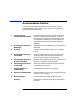
Quick Reference Agilent Technologies Sales and Service Offices Agilent Technologies Sales and Service Offices Table 9-5 Sales and Service Offices UNITED STATES Instrument Support Center Agilent Technologies, Inc. (800) 403-0801 EUROPEAN FIELD OPERATIONS Headquarters France Agilent Technologies France Agilent Technologies S.A. 1 Avenue Du Canada 150, Route du Nant-d’Avril Zone D’Activite De 1217 Meyrin 2/ Geneva Courtaboeuf Switzerland F-91947 Les Ulis Cedex (41 22) 780.
Quick Reference Agilent Technologies Sales and Service Offices INTERCON FIELD OPERATIONS Headquarters Australia Agilent Technologies Agilent Technologies Australia 3495 Deer Creek Rd. Ltd. Palo Alto, CA 94304-1316 31-41 Joseph Street USA Blackburn, Victoria 3130 (650) 857-5027 (61 3) 895-2895 Japan Agilent Technologies Japan, Ltd. Measurement Assistance Center 9-1, Takakura-Cho, Hachioji-Shi Tokyo 192-8510, Japan TEL (81) -426-56-7832 FAX (81) -426-56-7840 Singapore Agilent Technologies Singapore (Pte.
Glossary Glossary-1
Glossary Glossary 10Base-T A physical network connection that uses twisted-pair cables with RJ-45 connectors. absolute pathname (The specification of a node (file or directory) in a hierchical file system relative to the root directory (the topmost node)—It is the full path name of a file or directory, including all the directories leading to it, starting with the root (/) and ending with the file or directory name itself. bridge A device that moves traffic from one network to another.
Glossary The client and server must share a common protocol for client-server communication to occur. Ethernet A network that adheres to the IEEE 802.3 Local Area Network standard. Ethernet address A hexadecimal number which is used to identify a machine on a network. Each analyzer is assigned a unique Ethernet address at the factory and it is stored in the analyzer's ROM. host A computer or device on a network. host name A unique name that is used to identify each host machine on a network.
Glossary An IP address consists of a 32-bit value presented in decimal dot notation: 4 octets (bytes) separated by a dot. For example, the binary address 10000000 00000111 00001111 00000001 has the decimal dot notation of 128.7.15.1 network administrator Similar to “system administrator”. network logging The collection and recording of network performance measures and other parameters and statistics. NFS (Network File System) A standard network protocol for file sharing among different operating systems.
Glossary Protocol Function BOOTP client FTP server NFS client SICL LAN server SICL LAN A LAN protocol using the Standard Instrument Control Library (SICL). It provides control of instruments over the LAN, using a variety of computing platforms, I/O interfaces and operating systems. socket An endpoint for communication over a network. A socket, consisting of a port number and a network address, is part of a mechanism for creating a virtual connection between two processes.
Glossary time out A period of system inactivity during which the system awaits user or network response. If there is no response by the end of the period, the system takes an action. UDP (User Datagram Protocol) A protocol for passing data on an IP network. UDP does not guarantee delivery, and does not require a connection. It is a lightweight and efficient protocol, but all error processing and retransmission of data must be done by the application program. Specified by RFC-768.
Index data.
Index file system, analyzer, 4-2–4-9 file transfer program, 4-2 file transfer protocol, 4-2 file, copying, 4-5, 4-6 filename compatibility, UNIX to DOS, 4-6 FTP, 4-2, 9-6, Glossary-3 ftp, 4-1, 4-2, Glossary-3 ftp commands, 4-8 ftp, UNIX, 4-3 G gateway, 8-15, Glossary-3 gateway address, 1-9 Gateway IP Address key, 1-10, 8-15 get, 4-9 get command, 4-6 GPIB device address, 6-43 logical unit number, 6-43 name, 6-43 group ID, 7-5 setting up, 7-9 GUI FTP software, 4-10 H hardcopy, 3-2 hardcopy address, 3-5 hardc
Index removing, 1-14 pathname absolute, Glossary-2 relative, Glossary-4 Perl script, example, 6-28–6-30 ping, 1-11, 1-12, 8-5–8-9, 9-8, Glossary-4 point-to-point connection, 1-7 printer configuration, 3-3 printer connections, 1-7 printers, compatible, 3-2 printing, 3-2 printing configuration, 3-4 printing, color, 3-5 problems and solutions, 8-2 product documentation, 2-10 product feedback, 2-11 product support, 2-11 prog.bas, 5-2, 5-7, 9-9 prog_run.bas, 5-2, 5-7, 5-9, 9-9 prog_run.
Index unmounting a remote file system, 7-10 user ID, 7-5 setting up, 7-9 user names adding, 1-13 default, 1-13 removing, 1-14 W wiring, EIA/TIA 568B, 9-2–9-4 wizards, 1-21 4 Index