Agilent Technologies E1442A 64-Channel Form C Switch Module User’s Manual Manual Part Number: E1442-90003 Printed in U.S.A.
Appendix A Specifications .............................................................................................................. 85 Appendix B Register-Based Programming ................................................................................... 87 About This Appendix .................................................................................................. 87 Register Programming vs. SCPI Programming..........................................................
Notes: 6
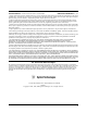
AGILENT TECHNOLOGIES WARRANTY STATEMENT AGILENT PRODUCT: E1442A 64-Channel Form C Switch Module DURATION OF WARRANTY: 3 years 1. Agilent Technologies warrants Agilent hardware, accessories and supplies against defects in materials and workmanship for the period specified above. If Agilent receives notice of such defects during the warranty period, Agilent will, at its option, either repair or replace products which prove to be defective. Replacement products may be either new or like-new. 2.
Documentation History All Editions and Updates of this manual and their creation date are listed below. The first Edition of the manual is Edition 1. The Edition number increments by 1 whenever the manual is revised. Updates, which are issued between Editions, contain replacement pages to correct or add additional information to the current Edition of the manual. Whenever a new Edition is created, it will contain all of the Update information for the previous Edition.
DECLARATION OF CONFORMITY According to ISO/IEC Guide 22 and CEN/CENELEC EN 45014 Manufacturer’s Name: Manufacturer’s Address: Agilent Technologies, Inc. Measurement Products Unit 815 14th Street S.W. Loveland, CO 80537 USA Declares, that the product Product Name: Model Number: Product Options: 64-Channel Form C Switch E1442A This declaration includes all options of the above product(s).
Notes: 10
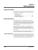
Chapter 1 Getting Started Using This Chapter This chapter shows how to get started using the E1442A 64-Channel Form C Switch Module. It gives guidelines to configure, install and program the module. Chapter contents include: • Switch Description . . . . . . . . . . . . . . . . . . . . . . . . . . . . . . . . . . .9 • Configuring the Switch . . . . . . . . . . . . . . . . . . . . . . . . . . . . . . .14 • Configuring the Terminal Modules . . . . . . . . . . . . . . . . . . . . . .
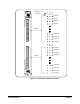
(Column #) (a) (b) (c) C NC NO (Row #) Channel 0 (32) Channel 1 Channel 2 Channel 3 (Bank A) Channel 28 Channel 29 Channel 30 Channel 31 (1) (a) (b) (c) C NC NO (32) Channel 32 Channel 33 Channel 34 Channel 35 (Bank B) Channel 60 Channel 61 Channel 62 (1) Channel 63 Figure 1-1.
Switch Block Diagram Figure 1-2 is a simplified block diagram of the Form C switch with internal bus and available terminal modules (Standard, Option 010, and Option 020).
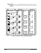
Terminal Module Descriptions Standard Configuration Figure 1-3 shows the Standard Terminal Module Form C configuration with solder lugs, the Option 010 Terminal Module Form C configuration with signal conditioning circuitry, and the Option 020 Form A Screw Terminal configuration. Option 020 Form A Option 010 Form C Figure 1-3. Form C Switch - Terminal Modules Figure 1-4 shows the three terminal modules and options for NO and NC connections for each terminal type.
Standard Terminal Module Channel 00 NO NO NC NC +V Loads 2 COM 1 COM Option 010 Terminal Module Channel 00 NO NO +V Loads 2 COM Signal Conditioning Circuitry NC 1 COM Option 020 Form A Screw Terminal Module Channel 00 NO Note: This is a Form A switch configuration. There is no terminal module connection to the relay’s NC contact. NC NO +V Load 2 COM NC COM Figure 1-4.
Configuring the Switch This section gives guidelines to configure the switch, including the following items. See "Configuring the Terminal Modules" for information on configuring the terminal modules.
Chapter 1 CAUTION WIRING TERMINAL MODULE: When wiring to the terminal connectors on a terminal module, do not exceed a 5mm strip back of insulation to prevent the possibility of shorting to other wiring on adjacent terminals. CAUTION STATIC-SENSITIVE DEVICE. Use anti-static procedures when removing, configuring, cleaning and installing a module. Since the switch module is susceptible to static discharges, do not install the module without its metal CAUTION CLEANING THE FRONT PANEL.
Setting the Logical Address The E1442A switch module logical address is set with the Logical Address Switch (LADDR) on the module. The factory setting for the LADDR is 120. Valid addresses are from 1 to 254. The module logical address value is set by the sum of the decimal values of the switches that are CLOSED. Example: Setting a LADDR For example, in Figure 1-5, switches 3, 4, 5, and 6 are CLOSED.
Figure 1-6 shows some examples of single- and multiple-module switchbox arrangements.For the multiple-module switchbox (top figure), the channel address (channel_list) has the form (@ccnn) where cc = card number and nn = channel number. For example, channel 45 on card number 02 is addressed by (@245). The multiple- and single-module switchbox (bottom figure), has two switchboxes: a multiple-module switchbox at logical address 120 and a single-module switchbox at address 48.
Setting Interrupt Priority Interrupts are enabled at power-up, after a SYSRESET, or after resetting the module via the control register. An interrupt is generated after any channel enable register is accessed when interrupts are enabled. The interrupt is generated approximately 13 ms after one of the registers is accessed. The interrupt priority jumper selects which priority level will be asserted. The interrupt priority jumper is set in position 1 as shipped from the factory.
Using the Internal Buses The E1442A 64-Channel Form C Switch Module contains internal buses to which you can connect any channel contact. Figure 1-8 shows channels 0 and 63 and the internal bus structure. There is a bus for the common (C), the normally closed (NC), and the normally open (NO) contacts. Other jumpers provide the means to connect the NC and NO contacts to a fused +5V pull-up voltage, or to be connected as pull-downs to ground. The common can be connected to ground.
Relay Connections Bus Connections Figure 1-9.
Installing the Switch in a Mainframe 1 The E1442A switch module can be installed in any slot (except Slot 0) of a C-size VXIbus mainframe. See Figure 1-10 for installation steps. Set the extraction levers out. 2 Slide the E1442A into any slot (except slot 0) until the backplane connectors touch. 3 4 Seat the E1442A into the mainframe by pushing in the extraction levers. Tighten the top and bottom screws to secure the E1442A to the mainframe.
Configuring the Terminal Modules This section gives guidelines to configure the Standard Form C Configuration, Option 010 Form C Configuration, and the Option 020 Form A Configuration terminal modules, including: • Wiring the Terminal Modules • Attaching Terminal Modules to the Switch Module • Configuring the Option 010 Terminal Module Wiring the Terminal Modules Figure 1-11 and Figure 1-12 show steps to wire terminal module s. Maximum terminal wire size is No. 16 AWG. Wire ends should be stripped 5mm (0.
4 Replace wiring exit panel and route wiring. Keep wiring exit panel hole as small as possible. Cut required holes in panels for wire exit 5 Replace Clear cover. A. Hook the top cover tabs onto the fixture. B. Press down and tighten screws. Tighten wraps to secure wires. Figure 1-12.
Attaching Terminal Modules to the Switch Module 1 See Figure 1-13 for steps to attach a terminal module to the switch module. Extend the extraction levers on the terminal module. Extraction Lever E1442A Extraction Lever 2 Align the terminal module connectors to the E1442A connectors. 3 Apply gentle pressure to attach the terminal module to the E1442A. 4 Push in the extraction levers to lock the terminal module onto the E1442A.
Configuring the Option 010 Terminal Module Terminal Module User Connections This section describes the Option 010 Terminal Module. With this terminal module, you can add components to configure a variety of passive signal conditioning circuits including pullups, pulldowns, and single-ended and differential resistive dividers and filters. User inputs are connected to the module by soldering wires or components to the terminal module PC board.
Figure 1-15.
Example: Straight-Through Configuration Any channel of the terminal module can be configured as a straight-through Form C relay. In this mode no resistors or capacitors are included. A two-position jumper is placed on the mode selection jumper. Figure 1-16 shows a typical straight-through configuration. No components are added. Set one configuration jumper as shown in Figure 1-16 (INLINE).
Example: Resistor Divider Configuration Any channel can be configured as a resistor divider connected to the normally open (NO) contact of the Form C relay. The user-supplied SIP resistor can be replaced by a standing resistor with it inserted in the solder hole of the SIP and a solder hole directly across from it. The row of solder holes is connected to V24-31. Figure 1-17 shows the voltage solder holes and identifies the voltage to which the row is connected.
Example: Low-Pass Filter Configuration Any channel can be configured as a low-pass filter connected to the normally open contact of the Form C relay. Figure 1-18 shows a typical low-pass filter configuration. For this example, resistor R25 and capacitor C25 are to be added. No configuration jumpers are required.
Example: Common Terminal Pullup Configuration Any channel can be configured as a pullup (or pulldown) resistor connected to any of the contacts of the Form C relay. Figure 1-19 shows a typical channel 25 with the pullup attached to the COM contact. For this example, the SIP resistor pack RP24-31 is to be added. Set two configuration jumpers as shown in Figure 1-19 (PU COM).
Example: Normally Closed Terminal Pullup Configuration Any channel can be configured as a pullup (or pulldown) resistor connected to any of the contacts of the Form C relay. Figure 1-20 shows channel 25 with the pullup attached to the NC contact. For this example, SIP resistor pack RP24-31 is to be added. Set two configuration jumpers as shown in Figure 1-20 (PU NC).
Example: Normally Open Terminal Pullup Configuration Any channel can be configured as a pullup (or pulldown) resistor connected to any of the contacts of the Form C relay. Figure 1-21 shows channel 25 with the pullup attached to the NO contact. For this example, SIP resistor pack RP24-31 is to be added. Set two configuration jumpers as shown in Figure 1-21 (PU NO).
Example: Divider with Filter Configuration Any channel can be configured as a resistor divider with a low-pass filter connected to the normally open contact of the Form C relay. Figure 1-22 shows a typical divider with filter configuration. For this example, resistor R25, capacitor C25, and SIP resistor pack R24-31 are to be added. Set one configuration jumper as shown in Figure 1-22 (LP/DIV).
Example: Differential Divider or Filter Configuration Any channel can be configured as a differential divider (with optional filter) connected to the normally open contact of the Form C relay. The differential divider requires that two channels be used. Figure 1-23 shows channel 24 and 25 in this configuration with the optional filter. For resistors R24 and R25, add a cross-channel capacitor for a differential filter or add a cross-channel resistor for a differential divider.
Programming the Switch This section gives guidelines and examples to program the E1442A 64-Channel Form C switch module using Standard Commands for Programmable Instruments (SCPI), including: • Specifying SCPI Commands • Start-up Exercises Specifying SCPI Commands NOTE To program the E1442A switch using SCPI, you must select the computer language, interface address, and SCPI commands to be used. Guidelines to select SCPI commands for the switch follow.
128 64 32 16 8 4 2 1 Card Number 01 Switch Module Logical Address = 120 Secondary Address = 15 Command Module 128 64 32 16 8 4 2 1 Card Number 02 Switch Module Logical Address = 121 128 64 32 16 8 4 2 1 Card Number 03 Switch Module Logical Address = 122 Note: Physical placement of the Module in the Logical Address order is not required, but is recommended. Figure 1-24.
Start-Up Exercises This section provides a set of four start-up exercises you can use to quickly get your E1442A 64-Channel Form C Switch operational, including: • Exercise 1: Check Device Driver (E1406A only) • Exercise 2: Query Module Identity • Exercise 3: Perform Open, Close, and Scan Operations • Exercise 4: Check for System Errors NOTE Exercise 1: Check Device Driver We recommend you do not make user connections to the switch until you have verified correct switch operation.
Exercise 2: Query Module Identity Turn mainframe power OFF. If you want to set a logical address other than the factory-set address of 120, see "Setting the Logical Address" to set a different logical address for the switch. Install the switch module in the mainframe. See "Installing the Switch in a Mainframe" for steps to install the switch. NOTE If you have already connected user inputs to the terminal module, you may want to disconnect the terminal module from the switch module for this exercise.
(1' :+,/( 287387 67$7 23(5" (17(5 $ 35,17 67$7 23(5 (9(17 %,7 $ (1' !Query the status operation event register !Bit 8 reported high (status byte bit 7 was high) !Print response to the STAT:OPER query RUN the program. You should hear channel relays opening and closing, especially when a large channel list is scanned.
Notes: 42 Getting Started Chapter 1
Chapter 2 E1442A Application Examples Using This Chapter This chapter provides application information and examples for using the E1442A 64-Channel Form C Switch Module in a switchbox. The chapter contents are: • General Scanning Information . . . . . . . . . . . . . . . . . . . . . . . . .41 • Saving and Recalling States . . . . . . . . . . . . . . . . . . . . . . . . . . .44 • Detecting Error Conditions . . . . . . . . . . . . . . . . . . . . . . . . . . . .44 • Scanning with External Instruments . . .
How to Scan Scanning Form C switch channels consists of closing a set of channels (connecting NO to C) one channel at a time. Single scan, multiple ($50 &281W to $50 &281W ) scans, or continuous ,1,7 &217) scanning modes are available. See the command reference in Chapter 3 for more information on these commands. Table 2-1 shows a number of SCPI commands that relate to scanning. Command Description ARM:COUNt Sets the number of scanning cycles per INIT (optional).
Using Scanning Trigger Sources The 75,* 6285 command specifies the source to advance the scan. You can use the 75,* command to advance the scan when 75,* 6285 %86 or 75,* 6285 +2/' is set. The 2873XW command can be used to enable the E1406A Command Module Trig Out port. Using the Scan Complete Bit You can use the Scan Complete bit (bit 8) in the Operation Status Register of a switchbox to determine when a scanning cycle completes (no other bits in the register apply to the switchbox).
Saving and Recalling States This section contains information about saving and recalling a switch module state. The switchbox driver can store up to 10 states. Saving States The 6$9 QXPHULFBVWDWH! command saves the current instrument state. The state number (0-9) is specified in the state parameter.
Example: Error Checking Using Interrupts The second approach to error checking involves the use of interrupts. The following program is a method of checking for errors using interrupts as you program the switch module. The program monitors the switch’s Standard Event Status Register for an error condition. If no errors occur, the switch module functions as programmed. If errors do occur, the switch module interrupts the computer, and the error codes and messages are read from the error queue.
Scanning with External Instruments Scanning Form C switch channels has the same effect as executing multiple CLOSe commands. Thus, scanning is useful when the outputs from a number of devices under test (DUTs) are to be measured with an instrument. Three examples using BASIC programming language follow. Example: Scanning with External Device This example uses the E1406 Command Module Trig Out port to synchronize the Form C switch channel closures to an external measurement device.
10 OUTPUT 722;"TRIG EXT;...." 20 OUTPUT 70915;"OUTP ON" 30 OUTPUT 70915;"TRIG:SOUR BUS" 40 OUTPUT 70915;"SCAN (@100:102)" 50 OUTPUT 70915;"INIT" 60 FOR I=1 TO 3 70 ENTER 722;A 80 PRINT A 90 TRIGGER 70915 100 NEXT I 110 END Example: Scanning Using Trig Out and Trig In Ports ! Configure instrument ! Enable Trig Out port ! GPIB bus triggering ! Scan channels 00-02 ! Enable scan.
1. 2. 3. 4. 5. 6. 7. 10 20 30 40 50 60 70 80 90 ,1,7 (line 50) closes channel 100. Closure causes trigger to be output from Trig Out port. Trigger to Ext Trig In initiates channel 100 measurement. Channel 100 measurement result stored in instrument. Trigger is then output from Measurement Complete port. Trigger to Event In port advances scan to channel 101. Steps 2-6 are automatically repeated for channels 101-102. OUTPUT 722;"TRIG EXT; ....
Chapter 3 E1442A Command Reference Using This Chapter This chapter describes Standard Commands for Programmable Instruments (SCPI) and summarizes IEEE 488.2 Common (*) commands applicable to the E1442A 64-Channel Form C Switch Module. This chapter contains the following sections: • Command Types. . . . . . . . . . . . . . . . . . . . . . . . . . . . . . . . . . . .49 • SCPI Command Reference . . . . . . . . . . . . . . . . . . . . . . . . . . .51 • SCPI Commands Quick Reference . . . . . . . . . . . . . .
Command Separator A colon (:) always separates one command from the next lower-level command as shown below: [ROUTe:]SCAN:MODE? Colons separate the root command from the second-level command [ROUTe:]SCAN) and the second level from the third level (SCAN:MODE?). Abbreviated Commands The command syntax shows most commands as a mixture of upper- and lowercase letters. The uppercase letters indicate the abbreviated spelling for the command. For shorter program lines, send the abbreviated form.
Parameters ParameterTypes. The following table contains explanations and examples of parameter types you might see later in this chapter. Type Explanations and Examples Numeric Accepts all commonly used decimal representations of numbers including optional signs, decimal points, and scientific notation. Examples are 123, 123E2, -123, -1.23E2, .123, 1.23E-2, 1.23000E-01. Special cases include MIN, MAX and INF. Boolean Represents a single binary condition that is either true or false. (ON, OFF, 1.0).
ABORt The ABORt command stops a scan in progress when the trigger sources are either TRIGger:SOURce BUS or TRIGger:SOURce HOLD. See the comments to stop a scan if trigger source is not BUS or HOLD. Subsystem Syntax Comments ABORt Channel Status After an ABORt: ABORting a scan will leave the last channel that it closed in the closed position. Effect on Scan Complete Status Bit: ABORting a scan will not set the "scan complete" status bit.
NOTE Clearing the interface using a Ctrl+C from the terminal during a scan leaves the last channel it closed in the closed position and does not set the Scan Complete status bit.
ARM The ARM subsystem allows a scan list to be scanned multiple times (1 through 32767) with one INITiate command. Subsystem Syntax ARM :COUNt MIN | MAX :COUNt? [MIN | MAX] ARM:COUNt ARM:COUNt allows scanning cycles to occur a multiple of times (1 to 32767) with one INITiate command and when INITiate:CONTinuous OFF | 0 is set.
Parameters Comments Example Name Type Range of Values Default Value MIN | MAX numeric MIN = 1 | MAX = 32,767 current cycles Related Commands: INITiate:IMMediate Query Number of Scanning Cycles $50 &281 $50 &281" Chapter 3 Set 10 scanning cycles Query number of scanning cycles. Returned value is 55.
DISPlay The DISPlay subsystem monitors the channel state of a selected module (or card) in a switchbox. The DISPlay command subsystem only operates with an RS-232 terminal connected to the E1406 Command Module’s RS-232 port. These commands control the display on the terminal, and would in most cases be typed directly from the terminal keyboard. However, it is possible to send these commands over the GPIB interface and control the terminal’s display.
DISPlay:MONitor:CARD? DISPlay:MONitor:CARD? queries the setting of the :MONitor:CARD command and returns the module in a switchbox to be monitored. DISPlay:MONitor[:STATe] DISPlay:MONitor[:STATe] turns the monitor mode on or off. When monitor mode is on, the RS-232 terminal display presents an array of values indicating the open/close state of every switch on the module. This display is dynamically updated each time a switch is opened or closed.
Example Enabling the Monitor Mode ',63 021 &$5' ',63 021 Selects module #2 in a switchbox. Turns the monitor mode on. DISPlay:MONitor[:STATe]? DISPlay:MONitor[:STATe]? queries the monitor mode. The command returns a 1 if monitor mode is on or a 0 if monitor mode is off.
INITiate The INITiate subsystem selects continuous scanning cycles and starts the scanning cycle. Subsystem Syntax INITiate :CONTinuous :CONTinuous? [:IMMediate] INITiate:CONTinuous INITiate:CONTinuous enables or disables continuous scanning cycles for the switchbox. The setting of this command determines whether or not a subsequent INIT[:IMMediate] command will cause a continuous scan to occur.
Example Enabling Continuous Scans ,1,7 &217 21 6&$1 # ,1,7 Enables continuous scanning Sets channel list Starts scanning cycle INITiate:CONTinuous? INITiate:CONTinuous? queries the scanning state. With continuous scanning enabled, the command returns 1. With continuous scanning disabled, the command returns 0.
OUTPut The OUTPut subsystem enables one trigger line of the E1406 Command Module. It also can disable the active line. Subsystem Syntax OUTPut :ECLTrgn [:STATe] [:STATe]? [:EXTernal] [:STATe] [:STATe]? :TTLTrgn [:STATe] [:STATe]? OUTPut:ECLTrgn[:STATe] OUTPut:ECLTrgn[:STATe] enables (ON or 1) or disables (OFF or 0) the ECL trigger bus pulse on the VXI bus line specified by n. There are two ECL trigger lines on the VXI bus allowing valid values for n to be 0 and 1.
OUTput:[EXTernal][:STATe] OUTPut[:EXTernal][:STATe] enables or disables the Trig Out port on the E1406A Command Module. OUTPut[:EXTernal][:STATe] ON | 1 enables the port and OUTPut[:EXTernal][:STATe] OFF | 0 disables the port. Parameters Comments Name Type Range of Values Default Value boolean 0 | 1 | ON | OFF OFF | 0 Abbreviated Syntax: OUTPut subsystem commands [:EXTernal] and [:STATe] are optional subcommands.
OUTPut:TTLTrgn[:STATe] OUTPut:TTLTrgn[:STATe] enables (ON or 1) or disables (OFF or 0) the TTL trigger bus pulse on the VXI bus line specified by n. There are eight TTL trigger lines on the VXI bus (n = 0 through 7). Parameters Comments Name Type Range of Values Default Value n numeric 0 through 7 N/A boolean 0 | 1 | ON | OFF OFF | 0 When OUTPut:TTLTrgn[:STATe] ON is set, a trigger pulse occurs each time a channel is closed during a scan.
[ROUTe:] The [ROUTe:] subsystem controls switching and scanning operations for the Form C switch modules in a switchbox. Subsystem Syntax [ROUTe:] CLOSe CLOSe? OPEN OPEN? SCAN :MODE :MODE? [ROUTe:]CLOSe [ROUTe:]CLOSe activates the Form C switch relay for the channels specified in the channel_list. The relay’s Common (C) terminal is connected to the Normally Open (NO) terminal.
Example Closing Form C Switch Channels This example closes channel 00 of card number 1 Form C switch module and channel 15 of card number 2 Form C switch module in a single switchbox. &/26 # 100 closes channel 00 of Form C switch #1. 215 closes channel 15 of Form C switch #2. [ROUTe:]CLOSe? [ROUTe:]CLOSe? returns the current state of the channel(s) queried. The channel_list is in the form (@ccnn).
Opening Channels: To open: • a single channel, use [ROUTe:]OPEN (@ccnn) • for multiple channels, use [ROUTe:]OPEN (@ccnn,ccnn) • sequential channels, use [ROUTe:]OPEN (@ccnn:ccnn) • a group of sequential channels, use [ROUTe:]OPEN (@ccnn:ccnn,ccnn:ccnn) • or any combination of the above Opening Order: A list of channels will not all open simultaneously. The order channels open when specified from a single command is not guaranteed. Use sequential OPEN commands if needed.
[ROUTe:]SCAN [ROUTe:]SCAN defines the channels to be scanned. The channel_list is in the form (@ccnn), (@ccnn,ccnn), or (@ccnn:ccnn) where cc = card number (00-99) and nn = channel number (00-63 and 99). See the comments for explanation of using the special case of 99 in the channel list.
287387 75,* (;7 '&9 Sets multimeter to external trigger and to measure dc volts. 287387 2873 21 Enables Trig Out port on command module.
Related Commands: SCAN *RST Condition: [ROUTe:]SCAN:MODE NONE [ROUTe:]SCAN:MODE? [ROUTe:]SCAN:MODE? returns the current state of the scan mode. The command returns NONE or VOLT to indicate which mode the scan is set.
STATus The STATus subsystem reports the bit values of the Operation Status Register (in the command module). It also allows you to unmask the bits you want reported from the Standard Event Register and to read the summary bits from the Status Byte Register. Subsystem Syntax Comments STATus :OPERation :CONDition? :ENABle :ENABle? :EVENt]? :PRESet The STATus system contains four software registers that reside in a SCPI driver, not in the hardware (see Figure 3-1) Two registers are under IEEE 488.
Standard Event Register NOTE: *ESR? Automatically Set at Power On Conditions Automatically Set by Parser Set by *OPC Related Commands are *OPC? and *WAI QUE = Questionable Data MAV = Message Available ESB = Standard Event RQS = Request Service OPR = Operation Status C = Condition Register EV = Event Register EN = Enable Register SRQ = Sevice Request *ESE *ESE? Power On User Request Command Error Execution Error Device Dependent Error Query Error Request Control Operation Complete 0 1 2 3 4
STATus:OPER:CONDition? STATus:OPERation:CONDition? returns the state of the Condition Register in the Operation Status Group. The state represents conditions which are part of the instrument’s operation. The SWITCH driver does not set bit 8 in this register (see STAT:OPER:EVENt?). STATus:OPERation:ENABle STATus:OPERation:ENABle sets an enable mask to allow events recorded in the Event Register to send a summary bit to the Status Byte Register (bit 7).
STATus:OPERation[:EVENt]? STATus:OPERation[:EVENt]? returns which bits in the Event Register (Operation Status Group) are set. The Event Register indicates when there has been a time-related instrument event. Comments Setting Bit 8 of the Operation Status Register: Bit 8 (Scan Complete) is set to 1 after a scanning cycle completes. Bit 8 returns to 0 after sending the STATus:OPERation[:EVENt]? command.
SYSTem The SYSTem subsystem returns the error numbers and error messages in the error queue of a switchbox, and returns the types and descriptions of modules (cards) in a switchbox. Subsystem Syntax SYSTem :CDEScription? :CTYPe? :CPON ALL :ERRor? SYSTem:CDEScription? SYSTem:CDEScription? returns the description of a selected module (card) in a switchbox.
Comments Differences Between *RST and CPON: SYSTem:CPON only opens all channels of a selected module or all modules in a switchbox. *RST opens all channels of all modules in a switchbox and also sets all other settings to their power-on states. Example Set All Channels on Module #1 to Power-on State 6<67 &321 Sets module #1 channels to power-on state (open) SYSTem:CTYPe? SYSTem:CTYPe? returns the module (card) type of a selected module in a switchbox.
When the queue is empty, each following SYSTem:ERRor? query command returns 0, "No error". To clear all error numbers/messages in the queue, execute the *CLS command. Maximum Error Numbers/Messages in the Error Queue: The queue holds a maximum of 30 error numbers/messages for each switchbox. If the queue overflows, the last error number/message in the queue is replaced by -350, "Too many errors". The least recent error numbers/messages remain in the queue and the most recent are discarded.
TRIGger The TRIGger subsystem commands controls the triggering operation of the Form C switch modules in a switchbox. Subsystem Syntax TRIGger [:IMMediate] :SOURce :SOURce? TRIGger[:IMMediate] TRIGger[:IMMediate] causes a trigger to occur when the defined trigger source is TRIGger:SOURce HOLD or TRIGger:SOURce BUS. This can be used to trigger a suspended scan operation.
TRIGger:SOURce TRIGger:SOURce specifies the trigger source to advance the scanning channel list. Parameters Name Comments Type Range of Values BUS discrete *TRG command EXTernal discrete Trig in port HOLD discrete Hold triggering ECLTrgn numeric n = 0 or 1 TTLTrgn numeric n = 0 thru 7 IMMediate discrete Immediate triggering Enabling the Trigger Source: The TRIGger:SOURce command only selects the trigger source. The INIT[:IMMediate] command enables the trigger source.
Likewise, other drivers may consume trigger resources which may deny access to a particular trigger by the SWITCH driver. You should always release custody of trigger sources after completion of an activity by setting the trigger source to BUS or HOLD (TRIG:SOUR BUS | HOLD). Using Bus Triggers: To trigger the switchbox with TRIGger:SOURce BUS selected, use the IEEE 488.2 Common command *TRG or the GPIB Group Execute Trigger (GET) command. Trig Out Port Shared by Switchboxes: See the OUTPut command.
SCPI Commands Quick Reference The following table summarizes the SCPI Commands for the E1442A 64-Channel Form C Switch Module used in a switchbox. .
IEEE 488.2 Common Commands Reference The following table lists the IEEE 488.2 Common (*) commands accepted by the E1442A 64-channel Form C Switch Module. The operation of some of these commands is described in Chapter 2 of this manual. For more information on Common commands, refer to the user’s manual for your mainframe or to the ANSI/IEEE Standard 488.2-1987. The common commands *RCL, *SAV and *TST? do specific actions with the E1442A, as listed in the following table.
Notes: 84 E1442A Command Reference Chapter 3
Appendix A Specifications Maximum Input Voltage: High to Low 150VDC 150VAC RMS 210VAC Peak Power Up/Down States: All Open Any Terminal to Chassis 150VDC 150VAC RMS 210VAC Peak (Maximum with internal jumpers installed or use of Option 010 terminal module): Any Terminal to Chassis High to Low 60VDC 60VDC 30VAC RMS 30VAC RMS 42VAC Peak 42VAC RMS Typical Time to Open/Close a Channel: 13 msec Module Size/Device Type: C, register-based Installation Category: IC 1 Connectors Used: P1 and P2 Number of Slots: 1
1 Pollution: Any addition of foreign matter, solid, liquid or gaseous (ionized gases), that may produce a reduction of dielectric strength or surface resistivity. Pollution Degree: For the purpose of evaluating clearances (the shortest distance in air between two conductive parts), Pollution Degree 1 and Pollution Degree 2 are recognized for use in the micro-environment. Pollution Degree 1: No pollution or only dry, non-conductive pollution occurs. The pollution has no influence.
Appendix B Register-Based Programming About This Appendix This appendix contains the information you can use for register-based programming of the E1442A. The contents include: • Register Programming vs. SCPI Programming . . . . . . . . . . . .85 • Addressing the Registers . . . . . . . . . . . . . . . . . . . . . . . . . . . . .85 • Register-Based Programming the E1442A. . . . . . . . . . . . . . . .88 • Register Definitions. . . . . . . . . . . . . . . . . . . . . . . . . . . . . . . . . .
The Base Address A16 Address Space Outside the Command Module When reading or writing to a switch register, a hexadecimal or decimal register address is specified. This address consists of a base address plus a register offset. The base address used in register-based programming depends on whether the A16 address space is outside or inside the E1406 Command Module.
Register Offset The register offset is the register’s location in the block of 64 address bytes. For example, the switch’s Status/Control Register has an offset of 0416.
Register-Based Programming the E1442A The E1442A Form C Switch Module is a register-based slave device. There are 64 independent switches on the card which are controlled using the Switch Control Registers. There are four register types on this module: • Identifies Hewlett-Packard as the manufacturer and the card is an A16 register-based device. • Device Type Register - Identifies card as an E1442A. • Status/Control Register - When read from, it is used to return device-specific status information.
Register Access with Memory Mapping (Embedded Controller) When using an embedded controller, VXI A16 address space is usually mapped to some block of memory within the controller’s addressable memory space. See the manual for the specific embedded controller you are using to determine where VXI Al6 is mapped. There may be other methods of accessing the VXI backplane. The following method shows which Al6 addresses are calculated for a module.
If bit 6 is returned as a 0, interrupts are enabled. If bit 6 is returned as a 1, interrupts are disabled. Bit 14 is the MODID bit. When a 0 is returned in bit 14, the module has been selected with a high state on the P2 MODID line (this occurs during turn-on). If a 1 is returned, the module has not been selected. Switch Enable Register Writing to E1442A Registers Status/Control Register A read of any of the Switch Enable Registers always returns FFFF16, regardless of the channel states.
A switch is open when contact is made between the normally closed (NC) contact and common (C). A switch is closed when contact is made between the normally open (NO) contact and common (C). Any combination of open or closed states is allowed at one time for all channels on the module.
Register Definitions Manufacturer ID Register (read-only register) Address b+0016 15 14 Read 13 12 11 10 9 8 7 6 5 4 3 2 1 0 Manufacturer ID; Returns FFFFh = Hewlett-Packard A16 only register-based device. Device Type Register (read-only register) Address b+0216 15 14 13 12 11 Read 10 9 8 7 6 5 4 3 2 1 0 4 3 2 1 0 Returns 022816 for the E1442A module.
Switch Enable Registers You write to the switch enable registers to close (or open) a channel. Write a "1" to the register to close a relay (channel). Write a "0" to the register to open a relay (channel). Reading any Switch Enable Register will always return FFFF16 regardless of the channel states.
Programming Example Beginning of Program /* This program resets the E1442A, closes channels and reads the*/ /* switch’s relay control registers, opens channels and scans all 64*/ /* channels on the module. * #include #include #include #include #include
Close and Open Channels /********** close and open channels **********/ /* set all bits in register for channels 0-15 (offset 10) to 1 */ iwpoke((unsigned short *)(base_addr + 0x10), 0xffff); /* read the E1442A relay control registers and print their value*/ /* relay control registers always return FFFF (hex) */ chan_0_15_reg = iwpeek((unsigned short *)(base_addr + 0x10)); chan_16_31_reg = iwpeek((unsigned short *)(base_addr + 0x12)); chan_32_47_reg = iwpeek((unsigned short *)(base_addr + 0x14)); chan_48_6
/* scan channels 48-63 (register offset 16) */ for (k=0; k15; k++) { iwpoke ((unsigned short *)(base_addr + 0x16), ldexp(1,k)); delay (50); } /* set all bits to 0 to open last closed channel */ iwpoke ((unsigned short *)(base_addr + 0x16), 0); /* close session */ iclose(e1442a); } Reset Function /* end of main */ /**********************************************************/ void reset_sw(char *base_addr) /* reset the module; open all relays (write a 1 to status bit 0) */ /* delay 100 ms for reset then set
Appendix C E1442A Error Messages Error Types Table C-2 lists the error messages generated by the E1442A Form C Switch module firmware when programmed by SCPI. Errors with negative values are governed by the SCPI standard and are categorized in Table C-1. Error numbers with positive values are not governed by the SCPI standard. See the E1406 Command Module User’s Manual for further details on these errors. Table C-1.
Error Messages Table C-2. E1442A Error Messages Code Error Message Potential Cause(s) -211 Trigger ignored Trigger received when scan not enabled. Trigger received after scan complete. Trigger too fast. -213 Init Ignored Attempting to execute an INIT command when a scan is already in progress. -222 Data out of range Parameter value is outside valid range. -224 Illegal parameter value Attempting to execute a command with a parameter not applicable to the command.
Index E1442A User’s Manual Symbols *CLS, 83 *ESE, 83 *ESE?, 83 *ESR?, 83 *IDN?, 83 *OPC, 83 *OPC?, 83 *RCL, 83 *RST, 83 *SAV, 83 *SRE, 83 *SRE?, 83 *STB?, 83 *TRG, 83 *TST?, 83 *WAI, 83 A abbreviated commands, 52 ABORt subsystem, 54 addressing registers, 87 addressing the switch, 37 ARM:COUNt, 56 ARM subsystem, 56 attaching the terminal modules, 26 B base address, registers, 88 C command separator, 52 command types, 51 commands, 59 ARM:COUNt, 56 ARM:COUNt?, 56 DISPlay:MONitor:CARD, 58 DISPlay:MONitor[:ST
D declaration of conformity, 9 detecting error conditions, 46 device type register, reading, 91 DISPlay MONitor CARD, 58 DISPlay MONitor CARD?, 59 DISPlay MONitor STATe, 59 DISPlay MONitor STATe?, 60 DISPlay subsystem, 58 documentation history, 8 E E1442A command reference, 51 error conditions, detecting, 46 error messages, 99–100 error types, 99 examples Advancing Scan Using TRIGger, 79 Check Device Driver, 39 Closing Form C Switch Channels, 67 Common Terminal Pullup Configuration, 32 Differential Divider
R reading registers, 90–91 recalling states, 46 register access (command module), 90 register access (memory mapping), 91 register definitions, 94 register offset, 89 register types, 90 register vs.
Notes: 104 Index
Manual Part Number: E1442-90003 Printed in U.S.A.