User and Service Guide Publication number 01141-97002 July 2004 For Safety and Regulatory information, see the pages at the end of this book.
Agilent Technologies 1141A Differential Probe and 1142A Probe Control and Power Module This manual contains information for use and service of the differential probe system, the 1141A Differential Probe and 1142A Probe Control and Power Module. In this document, the two models will be treated as a system. Each of the two instrument models that make up the differential probe system has a serial number sticker. The sticker for the 1141A Differential Probe is inside the probe, in the bottom cover.
Contents 1 Operating the Probe Accessories Supplied 6 Accessories Available 8 To inspect the probe 9 Using the probe with other instruments Recommended Test Equipment 9 9 2 Calibration Tests and Adjustment Equipment Required The Test Board 26 Calibration Tests 26 27 dc Gain Accuracy 28 Bandwidth 34 CMRR Test 36 Calibration Test Record Adjustments 39 40 Probe Adjustment 40 Adjustment Procedure 42 Attenuator Adapter Adjustment 49 3 Service Introduction 54 Performance Specifications and Characte
Contents Theory of Operation 59 Differential Probe 60 Control and Power Module Attenuator Adapters 61 Test Board 62 Service Policy 60 63 Troubleshooting 64 Probe Troubleshooting 64 Probe Control and Power Module Troubleshooting Removing and Replacing Assemblies Differential Probe 66 Probe Adapters 68 Probe Control and Power Module Replaceable Parts 71 Parts List 71 Ordering Information 71 Direct Mail Order System 71 Manufacturers’ Codes 72 Exploded View 73 4 70 66 64
1 Operating the Probe 5
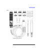
Operating the Probe Accessories Supplied Introduction This chapter shows you how to connect and operate the 1141A Differential Probe and 1142A Probe Control and Power Module as a differential probe system. Accessories Supplied The following items are supplied as part of the 1141A/1142A probe system. Item numbers refer to the numbers in Figure 1-1 on page -7 and Figure 1-2 on page -8. Those without item numbers are supplied but not shown in figures.
Operating the Probe Accessories Supplied Figure 1-1 1141A Differential Probe and Accessories 7
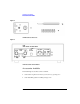
Operating the Probe Accessories Available Figure 1-2 1141A Miscellaneous Accessories Figure 1-3 1142A Probe Control and Power Module Accessories Available The following accessories can be ordered. • 5959-9335 Long Extension Lead (5.
Operating the Probe To inspect the probe To inspect the probe Inspect the shipping container for damage. If the shipping container or cushioning material is damaged, it should be kept until the contents of the shipment have been checked for completeness and the instrument had been checked mechanically and electrically. Accessories supplied with the instrument are listed in see “Accessories Supplied” on page 6 of this manual.
Operating the Probe Recommended Test Equipment Equipment Required Critical Specifications Recommended Agilent Model/Part Test Board No substitute (supplied accessory) 01141-66504 Load BNC Feedthrough, 50 Ω Pasternack P Enterprises PE600850 or Huber+Suhner 22543742 Cables (2) BNC, 50 Ω 36-inch 10503A P,A Cable BNC, 50 Ω 9-inch 10502A A Cable Type N (m) 24-inch 11500B P Adapter Type N (m) to BNC (f) 1250-0780 A Adapter Type N (f) to BNC (m) 1250-0077 P Adapters (2) BNC (f) to du
Operating the Probe Recommended Test Equipment WARNING Before connecting this instrument, the protective earth terminal of the instrument must be connected to the protective conductor of the (Mains) power cord. The Mains plug must be inserted in a socket outlet provided with a protective each contact. The protective action must be negated by the use on an extension cord (power cable) without a protective conductor (grounding).
Operating the Probe Recommended Test Equipment • Offset null zeroes the dc level at the output of the probe. The range of adjustment is about ±4 mV. • DC Reject Gain adjusts the gain of the dc reject circuit to accurately null the dc component of an input signal. The range of adjustment is about ±0.5%. Figure 1-5 1142A Front Panel Equipment Needed The following equipment is necessary for initial adjustment.
Operating the Probe Recommended Test Equipment 5 Set up the 1142A: a Set the Local/Remote push button to Local. b Under DC Couple, press Zero offset. 6 Set the power supply output to 5 V. 7 Arrange a connection between the power supply and the test board. The negative terminal of the supply should connect to the shield of the test board BNC. If your power supply has standard binding posts, you can connect a banana-to-BNC adapter to the supply and connect a BNC cable between the supply and the test board.
Operating the Probe Recommended Test Equipment Figure 1-7 Basic Accessory Connections Probe Tips Probe tips fit into the receptacles in the probe and are held in place with probe tip caps. If necessary, you can solder the probe tips into a circuit or wires can be soldered to the tips. If you solder to the probe tips, be careful not to melt the plastic probe tip caps.
Operating the Probe Recommended Test Equipment Note Use extension leads and similar connection accessories carefully. Extension leads compromise the high-frequency specifications of the probe. CMRR is particularly sensitive to unbalanced input parameters. To prevent pickup of stray fields when you use extension lead, either the ones supplied with the 1141A or others, dress them carefully as follows: • Connect the leads at right angles to the circuitry under test.
Operating the Probe Recommended Test Equipment Adapters There are three adapters for use with the differential probe. Two adapters are attenuators, a 10x and a100x. The other is an ac adapter for blocking dc from the probe input. The adapters are installed on the probe after the probe tip caps and probe tips have been removed. The adapter fastens to the probe using a thumb wheel located on the underside of the adapter. the figure below shows a good way to hold the probe while attaching the adapter.
Operating the Probe Recommended Test Equipment Adapter Combinations The figure below shows the allowed adapter and probe connections. There are two specific combinations that should not be used. • Do not attach the ac adapter between an attenuator adapter and the probe. An attenuator adapter must be terminated by the input resistance of the probe. The ac adapter isolates the probe input resistance. • Do not cascade two attenuator adapters.
Operating the Probe Recommended Test Equipment Connector Compatibility The following are general connector characteristics for the probe, adapters, and accessories. • The female connectors on the probe, adapters, and other accessories are designed to mate with 0.030-inch round or 0.0250-inch square pins. • The probe, adapter, and extension lead pins are 0.030-inch round. • The strip of circuit connection posts provided as an accessory has 0.025-inch square pins. • The mini-grabber has a 0.
Operating the Probe Recommended Test Equipment Probe System Coupling Functions dc offset dc Reject ac Coupling Adapter dc Blocked Probe alone Probe with 10x Probe with 100x Set-up needed ± 20 V ± 200 V ± 500 V Adjust offset to put signal on screen ± 20 V ± 200 V ± 500 V Select DC Reject low-frequency corner ± 20 V ± 500 V ± 500 V Attach ac Coupling adapter to differential probe Yes1 Yes1 No CMRR degradation? No No Yes Low-frequency degradation? No Yes Yes Remote Control? 1 Isolated exte
Operating the Probe Recommended Test Equipment To use dc reject: 1 Remove the ac adapter if it is installed. 2 On the front panel of the 1142A, press Local. 3 Under DC Reject on the front panel, press 5.0 Hz or 0.5 Hz individually, or 5.0 Hz and 0.5 Hz simultaneously to get 0.05 Hz. Within the frequency and voltage characteristics noted elsewhere in this manual, low frequencies are nulled from the input signal.
Operating the Probe Recommended Test Equipment To use ac coupling: 1 Attach the ac coupling adapter to the input of the probe or the input of the attenuator adapter. 2 On the 1142A, press Local and Zero offset. Remote operation For automatic test applications, the coupling and offset functions provided by the 1142A Probe Control and Power Module can be remotely controlled through a connector on the rear panel of the module. The connection is through a standard 9-pin female D-subminiature connector.
Operating the Probe Recommended Test Equipment Function Select The easiest way to control the function select lines is contact closures between the lines and Digital common (pin 2) of the remote input connector. (TTL compatible control signals can be used; but to avoid problems with ground loops, they must be electrically isolated.) The following truth table shows the functions provided by the function select lines. For the Remote Inputs, “0” represents a closure and “1” represents an open circuit.
Operating the Probe Recommended Test Equipment Differential Amplifiers and CMRR The 1141A Differential Probe is a high-impedance differential amplifier. A characteristic of differential amplifiers is the ability to reject signals that are common to the two inputs. The common mode rejection ratio (CMRR) is the measurement of this ability. It is expressed as the ratio between the amplitudes of the common mode and differential signals which product equal outputs.
Operating the Probe Recommended Test Equipment 24
2 Calibration Tests and Adjustment 25
Calibration Tests and Adjustment Equipment Required Introduction This chapter is divided into two sections. The first section gives calibration tests and the second adjustment procedures for the 1141A Differential Probe and 1142A Probe Control and Power Module. Equipment Required A complete list of equipment required for the calibration tests and adjustments is listed in “Recommended Test Equipment” on page 9. Equipment required for individual procedures is listed at the procedure.
Calibration Tests and Adjustment The Test Board Calibration Tests These procedures test the probe’s electrical performance using applicable specifications given in “Performance Specifications and Characteristics” on page 55 as performance standards. Specifications applicable to individual tests are noted at the test for reference.
Calibration Tests and Adjustment dc Gain Accuracy dc Gain Accuracy This test checks the dc gain accuracy of the differential probe and the dc accuracy of the differential probe with attenuator and adapters. Specification: Probe alone, ±2%; with attenuator adapter, ±4% Equipment Required Equipment Required Critical Specifications Recommended Agilent Model/Part ac/dc Calibrator or dc Power Supply 100 mV to 7 V DVM 0.
Calibration Tests and Adjustment dc Gain Accuracy Figure 2-2 2 Set up the 1142A probe control and power module as follows: a Set the Local/Remote push button to Local. b Under DC Couple, press the Zero offset button. 3 With the 1141A Probe Amp disconnected from the test PCA, adjust the Offset Null control on the 1142A until the DVM reads 0Vdc. If the probe output voltage cannot be set to 0V, subtract this voltage from the subsequent measurements in this test.
Calibration Tests and Adjustment dc Gain Accuracy Figure 2-3 Signal to - input 10 Calculate probe gain as ∆V out ( V out1 – V out 2 ) -------------- = ---------------------------------∆V in 2 × V in1 Record the result of this calculation in the “Calibration Test Record” on page 39. To pass this test, the probe gain = 0.98 to 1.02 NOTE Failure of the gain accuracy test can be caused by mis-adjustment of the probe.
Calibration Tests and Adjustment dc Gain Accuracy Figure 2-4 Signal to + input 3 4 5 6 Set the dc calibrator output 3 V dc. Record the Vin1 measurement from the top DVM in figure 2-2. Record the Vout1 measurement from the bottom DVM in figure 2-2 Carefully connect the input of the probe/attenuator to the test board in the position shown in the figure below (signal to - input). Figure 2-5 Signal to - input 7 Record the Vout2 measurement from the bottom DVM in figure 2-2.
Calibration Tests and Adjustment dc Gain Accuracy 100x Attenuator Accuracy Test NOTE If the gain test for the probe fails, it will be reflected in the test for the 100x attenuator adapter. Do not continue until the probe passes the gain test. 1 Disconnect the probe/attenuator from the test board. Remove the 10x attenuator adapter from the probe and connect the 100x attenuator adapter.
Calibration Tests and Adjustment dc Gain Accuracy 6 Carefully connect the input of the probe/attenuator to the test board in the position shown in the figure below (signal to - input). Figure 2-7 Signal to - input 7 Record the Vout2 measurement from the bottom DVM in figure 2-2.
Calibration Tests and Adjustment Bandwidth Bandwidth This test checks the high-frequency response of the 1141A Differential Probe. The bandwidth of the oscilloscope is characterized first so it is not a factor in the measurement.
Calibration Tests and Adjustment Bandwidth 6 Reconfigure the equipment. a Disconnect the signal generator cable from the oscilloscope input and connect it to the test board. b Connect the output of the differential probe to the channel 1 input of the oscilloscope. c Carefully connect the input of the probe to the test board in the position shown in the figure below (signal to + input). Figure 2-8 Signal to + input 7 Record the Vp-p reading on the oscilloscope.
Calibration Tests and Adjustment CMRR Test CMRR Test This test checks the CMRR at 1 MHz and 100 MHz.
Calibration Tests and Adjustment CMRR Test 7 On the oscilloscope, press AUTOSCALE and set the following parameters. Menu Selection Setting TIMEBASE (time/div) 500 ns/div CHAN 1 (sensitivity) (input R) 200 mV/div 50 Ω DC ACQUISITION Sampling Mode Memory Depth Sample Rate Averaging # of avg Real Time Automatic Automatic Enabled 32 8 On the oscilloscope, measure the peak-to-peak voltage of the channel 1 signal, then V P-P, then press 1) and record the reading.
Calibration Tests and Adjustment CMRR Test 15 Connect the input of the probe to the test board in the position shown in the figure below (signal to + input). Figure 2-11 Signal to + input 16 Set the signal generator for 100 MHz at 0.0 dBm (about 224 mVrms, 632 mVp-p). 17 Set the oscilloscope to channel 1 and change the horizontal scale to 5 ns/div. 18 After the measurement settles (averaging is complete), note the V P-P reading.
Calibration Tests and Adjustment Calibration Test Record Calibration Test Record 1141A/1142A Differential Probe Tested by_________________________ Serial No. ______________________________ Work Order No.____________________ Recommended Test Interval - 1 Year/2000 hours Date____________________ Recommended next testing_________________ Temperature_____________ Test Limits dc Gain Accuracy Probe Only +0.98 mV to +1.02 mV _____________ 10x +0.096 mV to +0.104 mV _____________ 100x +0.
Calibration Tests and Adjustment Probe Adjustment Adjustments This section provides adjustment procedures for the 1141A Differential Probe and attenuator adapters. There are no service adjustments for the 1142A Probe Control Module. Adjustment Interval None of the adjustment procedures that follow should be considered for a routine maintenance plan. The differential probe and attenuator adapters should be adjusted under conditions specified at the beginning of the respective procedures.
Calibration Tests and Adjustment Probe Adjustment The following equipment is required for this procedure. Procedures are based on the model or part number recommended. Equipment Required Equipment Required Critical Specifications Recommended Agilent Model/Part Function Generator 2.
Calibration Tests and Adjustment Adjustment Procedure 6 As shown in the figure below, use the grounding screw to reinstall the ground block on the PC assembly. Figure 2-13 Attaching Ground Block to Probe PC Assembly The ground block provides a mechanical and electrical connection when the probe PC assembly is connected to the test board. 7 Connect the probe power connector to the PROBE connection on the rear of the 1142A Probe Control and Power Module. 8 Connect the mains power to the 1142A.
Calibration Tests and Adjustment Adjustment Procedure 3 On the oscilloscope, then press CLEAR DISPLAY. Press AUTOSCALE, then set up the following parameters. Menu Selection Setting TIMEBASE (time/div) 500 ns/div CHAN 1 (sensitivity) (input R) 100 mV/div 50 Ω DC TRIG (mode) source level trg’d EXT 1.
Calibration Tests and Adjustment Adjustment Procedure 8 Center adjustment R11, HF CMRR (see following figure). Figure 2-15 R11, HF CMRR Adjustment 9 Adjust R9, HF GAIN so the Vp-p (1) measurement is the same as in step 4, within ±0.5%. Make the adjustment slowly so the oscilloscope display has time to react to signal averaging. Press CLEAR DISPLAY occasionally to restart averaging, which gives a quicker indication of changes.
Calibration Tests and Adjustment Adjustment Procedure 2 Change the oscilloscope settings to: Menu Selection Setting TIMEBASE (time/div) 50 µs/div CHAN 1 (sensitivity) 100 mV/div 3 Carefully connect the input of the probe to the test board in the position shown in the figure below (signal to + input). Figure 2-17 Signal to + input 4 Adjust R14 (LF Gain) and C4 (+ LF BANDWIDTH) for the flattest pulse top (see figure below).
Calibration Tests and Adjustment Adjustment Procedure 5 Carefully connect the probe to the test board in position shown in the figure below (signal to both inputs). Figure 2-19 Signal to both inputs 6 Change the function generator settings to: • Sine wave • 4 kHz • 1.0 Vp-p 7 Change the oscilloscope settings to: Menu Selection Setting TIMEBASE (time/div) 50 µs/div CHAN 1 (sensitivity) 2 mV/div 8 Adjust C6 (-LF BANDWIDTH) for minimum signal amplitude on the oscilloscope.
Calibration Tests and Adjustment Adjustment Procedure High Frequency Compensation This adjustment sequence continues from the Low Frequency Response and CMRR adjustment. However, it can be done separately if the probe meets all specifications except bandwidth. Adjust R13 for unity gain at 200 MHz. 1 Connect the signal generator to the test board and set it for 200 MHz and 300mVp-p (107 mVrms).
Calibration Tests and Adjustment Adjustment Procedure 4 Assemble the PC assembly in the top cover. The side of the PC assembly with the large hybrid is exposed when the assembly is in the top cover. The figure below shows how the top cover, PC board, and ground block fit together. Figure 2-22 Reassembling the Probe a Insert the input connectors first, and seat the cable end of the PC assembly over the pins at the rear of the cover. b Position the ground block at the center-front of the PC assembly.
Calibration Tests and Adjustment Attenuator Adapter Adjustment Attenuator Adapter Adjustment The following procedure should be used if it is necessary to adjust an attenuator adapter. Attenuator adapters have only characteristics; they do not have any specifications. An adapter will need adjustment only if one or more of the following occurs. • If an adapter is to be used on a different 1141A probe that it was calibrated with last.
Calibration Tests and Adjustment Attenuator Adapter Adjustment Adjustment Procedure NOTE The attenuator must be adjusted when installed on the 1141A probe with which it will be used. The specifications and characteristics will not be met if the attenuator adapter is adjusted with one differential probe then used with another. 1 Remove the probe pins from the attenuator adapter and differential probe, then attach the adapter to the probe. 2 Set the 1142A front panel switches to Local and Zero offset.
Calibration Tests and Adjustment Attenuator Adapter Adjustment 7 Connect the adapter/probe combination to the test board in the position shown in the figure below. Figure 2-23 Signal to + input 8 Adjust the + HF RESP for best overall pulse response, the flattest pulse top. Use the figure below for adjust locations. Figure 2-24 Adjustment Locations 9 Change the function generator to 10 Vp-p (10x adapter adjustment only). 10 On the oscilloscope, press CHAN and set the sensitivity to 1 mV/div.
Calibration Tests and Adjustment Attenuator Adapter Adjustment 11 Connect the adapter/probe combination to the test board in the position shown in the figure below (signal to both inputs). Figure 2-25 Signal to both input 12 Alternately adjust the LF CMRR and then the -HF RESP for a minimum signal on the oscilloscope. Repeat the adjustments until the signal is optimized to a minimum. Each adjustment should be set to minimize the component of the signal it affects most.
3 Service 53
Service Introduction Introduction This section provides troubleshooting, service, and repair information for the 1141A Differential Probe and 1142A Probe Control and Power Module. The troubleshooting information is provided to isolate a faulty assembly. When a faulty assembly has been located, the disassembly/assembly procedures help direct replacement of the assembly. WARNING Maintenance should be performed by trained service personnel aware of the hazards involved (for example, fire and electric shock).
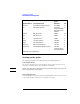
Service Performance Specifications and Characteristics Performance Specifications and Characteristics The following table gives performance specifications used to test the 1141A and 1142A. It also gives performance characteristics that are typical for the probe system. Performance Specifications and Characteristics Parameter Probe alone With 10x attenuator With 100x attenuator SPECIFICATIONS Bandwidth (-3 dB, dc coupled) dc to 200 MHz1 Rise Time: (calculated) 1.
Service Performance Specifications and Characteristics Figure 3-1 CMRR Specifications and Characteristics Legend A. CMRR specification for probe with no input adapters. B. Low-frequency CMRR specification for probe with the ac adapter. C. Typical CMRR characteristic for differential probe with no input adapters D. Typical CMRR characteristic for differential probe with 100x attenuator adapter at input. E. Typical CMRR characteristic for differential probe with 100x attenuator adapter at input.
Service Performance Specifications and Characteristics Figure 3-2 Maximum Input Voltage vs. Frequency Legend A. Input voltage limits for probe alone. B. Input voltage limits for 10x adapter. C. Input voltage limits for 100x adapter.
Service General Characteristics General Characteristics The following characteristics apply to the 1141A Differential Probe with the 1142A Probe Control and Power Module.
Service Theory of Operation Theory of Operation The following discussion covers block-level theory for the 1141A/1142A differential probe system. Refer to the block diagram below. The differential probe system consists of two units, the 1141A Differential Probe with its accessories and the 1142A Probe Control and Power Module. For purposes of the following discussion, these will be called the probe and the control module respectively.
Service Theory of Operation Differential Probe The probe contains a two-path differential amplifier with unity gain. It is implemented on a double-sided surface-mount PC board with the high-frequency path on one side and the low-frequency path on the other. The two paths are split directly after the differential input connections. High-Frequency Path The positive and negative inputs are ac-coupled at 33 Hz into identical impedance converters.
Service Theory of Operation Offset Functions There are two offset functions developed in the control module: variable offset and dc reject. A variable offset voltage with coarse and fine adjustments can be selected by the front panel controls. The offset level is buffered by U8 and selected by multiplexer U3 as the input to offset amp U7. The output of the offset amp is summed with the lowfrequency signal and feedback which gives dc coupling in the probe.
Service Theory of Operation Test Board The test board is a device for conveniently connecting test signals to the differential probe. The probe can be connected to the board with the signal to the positive, negative, or both inputs.
Service Service Policy Service Policy For parts of the 1141A/1142A probe system that are complex, the service policy is for assembly-level repair. For parts of the system with simple circuitry, the service policy is component-level repair. The service policy for the 1141A Differential Probe is assembly-level repair. Assemblies include the PC assembly and cable. The PC assembly is an “exchange assembly.” A repaired and tested assembly is shipped upon receipt of the defective assembly.
Service Troubleshooting Troubleshooting Use the following paragraphs to assist in troubleshooting problems with the 1141A/1142A Differential Probe. Probe Troubleshooting To troubleshoot the probe: 1 Apply a known signal to the input of the probe. 2 Check for an identical output at the output coax to the cable. This connection is the one soldered to the PC board. If the probe output cable is not terminated, or the coax is open, the output signal will be about twice the amplitude of the input signal.
Service Troubleshooting Figure 3-7 1142A Probe Control and Power Module 65
Service Removing and Replacing Assemblies Removing and Replacing Assemblies This section contains procedures for the removal and replacement of major assemblies. CAUTION Never remove or install any assembly with the instrument power ON. Component damage can occur. Differential Probe Use the following procedure to remove and replace the amplifier PC board in the differential probe. CAUTION ELECTROSTATIC DISCHARGE can damage electronic components.
Service Removing and Replacing Assemblies Reassemble Probe The ground screw passes through the top cover and PC board and screws into the ground block. 1 If replacing the PC board, remove the input connectors from the old board and put them on the new one. 2 If replacing the cable, note the orientation of the probe clamp ring on the old cable, remove the ring and put it on the new cable. 3 Connect the cable connector to the PC board. 4 Solder the two connections of the coaxial cable to the PC board.
Service Removing and Replacing Assemblies CAUTION Note where the two pins at the rear of the top cover enter the holes in the PC assembly. Position the cable wires away from these two areas. When the bottom cover is closed, part of it will pinch wires that are laying over these areas. b Insert the pins at the front of the bottom cover into the holes at the front of the top c cover. Close the covers together and fasten with the probe clamp ring.
Service Removing and Replacing Assemblies 2 Combine the thumbwheel screw and thumbwheel and insert them into the hole in the outer housing. 3 Insert the substrate/board into the outer housing. Slip the attenuator ground (attenuator adapters only) over the thumbwheel screw and seat the input connectors in the proper holes in the housing. Figure 3-10 Reassembling the Adapter Do not force reassembly of the adapter. The housing halves will slide together with moderate friction.
Service Removing and Replacing Assemblies Probe Control and Power Module Use the following procedure to disassemble the probe control and power module. WARNING Hazardous voltages exist on the power supply. To avoid electrical shock, adhere closely to the following procedures. 1 Remove the power cord. 2 Remove four flathead screws and remove the top cover. WARNING Be sure to reconnect the safety ground when reassembling the instrument.
Service Replaceable Parts Replaceable Parts This section contains information for ordering parts. Service support for the 1141A Differential Probe is to the assembly level. Service support for the adapters is as complete assemblies, except for the probe tip caps and the probe tips. Service support for the 1142A Probe Control and Power Module is to the component level. Parts List The replaceable parts lists include all parts relevant to the applicable service levels.
Service Replaceable Parts Mail order forms and specific ordering information are available through your local Agilent Technologies Sales Office. Addresses and telephone numbers are located in a separate document shipped with the manuals. Manufacturers’ Codes A list of manufacturers’ codes is given the table below. The codes are given for parts in the parts lists. The table gives the manufacturer and address for each code. Manufacturers’ Code List Mfr. No.
Service Replaceable Parts Exploded View Figure 3-11 1141A Differential Probe Parts 73
Service Replaceable Parts Figure 3-12 Power and Control Board Component Locator 74
Service Replaceable Parts Figure 3-13 Cabling Diagram 75
Service Replaceable Parts Figure 3-14 IC Connectors not Shown Supply +15 -15 GND +15 -15 NC +5 GND Pin No.
Service Replaceable Parts Figure 3-15 1142A Probe Control and Power Module 77
Service Replaceable Parts 1141A and 1142A Replaceable Parts Ref. Des. Part Number Qty Description Mfr. Code Mfr.
Service Replaceable Parts 1141A and 1142A Replaceable Parts Ref. Des. Part Number Qty Description Mfr. Code Mfr. Part Number A1 01142-66501 1 PC ASSEMBLY-POWER AND CONTROL 28480 01142-66501 H1 0515-0374 7 SCREW-MACHINE M3 10mm-LG 00000 ORDER BY DESP. H2 0515-1031 4 SCREW-MACHINE M3 6mm-LG 90-DEG-FLH-HD 00000 ORDER BY DESP. H3 0515-1579 1 SCREW-MACHINE M5 18mm-LG 00000 ORDER BY DESP.
Service Replaceable Parts Power Supply Replaceable Parts Ref. Des. Part Number Qty Description Mfr. Code Mfr. Part Number Prefix the reference designators with A1 C1 0160-6190 2 CAPACITOR-FXD 0.33UF ±10% 50VDC 28480 0160-6190 C2 0160-5474 1 CAPACITOR-FXD 0.1UF ±5% 100VDC MET-POLY 28480 0160-5474 C3 0180-3298 2 CAPACITOR-FXD 2200UF+30-10% 50VDC AL 28480 0180-3298 C4 0180-3298 CAPACITOR-FXD 2200UF+30-10% 50VDC AL 28480 0180-3298 C5 0160-6500 CAPACITOR-FXD 0.
Service Replaceable Parts Power Supply Replaceable Parts Ref. Des. Part Number Qty CR1 Description Mfr. Code Mfr.
Service Replaceable Parts Power Supply Replaceable Parts Ref. Des. Part Number Qty Description Mfr. Code Mfr. Part Number J1 1252-4731 1 CONNECTOR-AC PWR 28480 1251-4743 J2 1252-1487 1 CONN-RECT D-SUBMIN 9-CKT (remote) 28480 1252-1487 J3 1252-3935 1 CONNECTOR-ROUND 8-CKT (probe) 28480 1252-3134 MP1 1400-1604 1 LED MOUNT 28480 1400-1604 MP2 1205-0732 4 SPRING CLIP 28480 1205-0732 MP3 0361-0685 3 RIVET-BLIND DR-PIN RNDH 0.
Service Replaceable Parts Power Supply Replaceable Parts Ref. Des. Part Number R16 0698-6317 R17 Qty 2 Description Mfr. Code Mfr. Part Number RESISTOR 500 0.1% 0.125W TF TC=0±25 28480 0698-6317 0698-4002 RESISTOR 5K 1% 0.125W TF TC=0±100 24546 CT4-1/8-TO-5001-F R18 0699-1203 RESISTOR 120.0 1% 0.125W TF TC=0±25 28480 0699-1203 R19 0698-6317 RESISTOR 500 0.1% 0.125W TF TC=0±25 28480 0698-6317 R20 NOT ASSIGNED R21 0698-8827 R22 0757-0442 R23 0757-0427 R24 1 RESISTOR 1M 1% 0.
Service Replaceable Parts Power Supply Replaceable Parts Ref. Des. Part Number Qty Description Mfr. Code Mfr. Part Number RP1 1810-1242 1 RESISTOR NETWORK 28480 1810-1242 S1 3101-2609 1 SWITCH-SL DPST STD 5A 250VAC PC 28480 3101-2609 S2 3101-3007 1 SWITCH-6 STATION ASSEMBLY 28480 3101-3007 T1 9100-4750 1 TRANSFORMER-POWER (with mtg. hardware) 28480 9100-4750 U1 1826-1403 2 IC V RGLTER-ADJ-POS 3/40V 00000 LT317AT U2 1826-1670 2 IC V RGLTR-ADJ-NEG -37/1.
Service Replaceable Parts Locator Table for Control and Power Supply Ref. Des.
Service Replaceable Parts 86
Index Numerics 100x attenuator test, 32 10x attenuator test, 30 A ac adapter, 20 ac coupling adapters, 19 ac low frequency, 55 accessories available to order, 8 circuit connector posts, 15 extension leads, 14 ground leads, 14 mini grabbers, 15 probe tips, 14 shielded signal leads, 15 supplied with probe, 6 test board, 26 using, 13 accuracy test, attenuator, 30, 32 adapter combinations, 17 adapters, 16 attenuator, 61 adjustment, 11 attenuator adapter, 49 initial, 13 probe, 40, 42 altitude, 58 amplifiers, 23
Index M making measurements, 13 manufacturer’s codes, 72 maximum input voltage, 55 mini grabbers, 15 N noises, 55 O offset, 20 offset functions, 61 offset null, 11 operating environment, 58 operating range, 55 ordering information, 71 output impedance, 55 overload recovery, 55 P parts list, 71, 78 performance specification, 55 power module, 60 disassembly, 70 troubleshooting, 64 power requirements, 10, 58 power supply, 61 probe adapter disassembly, 68 reassembly, 68 probe adjustment, 40 probe control disas
Notices © Agilent Technologies, Inc. 2000-2004 No part of this manual may be reproduced in any form or by any means (including electronic storage and retrieval or translation into a foreign language) without prior agreement and written consent from Agilent Technologies, Inc. as governed by United States and international copyright laws. Manual Part Number 01141-97002, July 2004 Print History 01141-97000, June 2000 01141-97001, September 2002 01141-97002, July 2004 Agilent Technologies, Inc.
Product Safety Notices This apparatus has been designed and tested in accordance with IEC Publication 1010, Safety Requirements for Measuring Apparatus, and has been supplied in a safe condition. This is a Safety Class I instrument (provided with terminal for protective earthing). Before applying power, verify that the correct safety precautions are taken (see the following warnings). In addition, note the external markings on the instrument that are described under "Safety Symbols.