Installation and Quick Start Guide 8753ET/ES Network Analyzers Part Number: 08753-90471 Printed in USA Print Date: February 2001 Supersedes: May 2000
Notice The information contained in this document is subject to change without notice. Agilent Technologies makes no warranty of any kind with regard to this material, including but not limited to, the implied warranties of merchantability and fitness for a particular purpose. Agilent Technologies shall not be liable for errors contained herein or for incidental or consequential damages in connection with the furnishing, performance, or use of this material. © Copyright 1999-2001 Agilent Technologies, Inc.
Certification Agilent Technologies Company certifies that this product met its published specifications at the time of shipment from the factory. Agilent Technologies further certifies that its calibration measurements are traceable to the United States National Institute of Standards and Technology, to the extent allowed by the Institute's calibration facility, and to the calibration facilities of other International Standards Organization members.
General Safety Considerations WARNING For continued protection against fire hazard replace line fuse only with same type and rating (115V operation: T 5A 125V UL/ 230V operation: T 4A H 250V IEC). The use of other fuses or material is prohibited. WARNING This is a Safety Class I product (provided with a protective earthing ground incorporated in the power cord). The mains plug shall only be inserted in a socket outlet provided with a protective earth contact.
Documentation Map The Installation and Quick Start Guide provides procedures for installing, configuring, and verifying the operation of the analyzer. It also will help you familiarize yourself with the basic operation of the analyzer. The User’s Guide shows how to make measurements, explains commonly-used features, and tells you how to get the most performance from your analyzer. The Reference Guide provides reference information, such as specifications, menu maps, and key definitions.
Contents 1. Installing Your Analyzer Introduction . . . . . . . . . . . . . . . . . . . . . . . . . . . . . . . . . . . . . . . . . . . . . . . . . . . . . . . . . . . . . . . .1-2 STEP 1. Verify the Shipment . . . . . . . . . . . . . . . . . . . . . . . . . . . . . . . . . . . . . . . . . . . . . . . . . .1-3 STEP 2. Familiarize Yourself with the Analyzer Front and Rear Panels . . . . . . . . . . . . . . .1-5 Analyzer Front Panel . . . . . . . . . . . . . . . . . . . . . . . . . . . . . . . . . . . . . .
1 Installing Your Analyzer 1-1
Installing Your Analyzer Introduction Introduction This chapter shows you how to install your analyzer and confirm the correct operation, by following the steps below: 1. Verify the shipment. 2. Familiarize yourself with the analyzer front and rear panels. 3. Meet electrical and environmental requirements. 4. Configure the analyzer. 5. Verify the analyzer operation. 6. Back up the EEPROM disk.
Installing Your Analyzer STEP 1. Verify the Shipment STEP 1. Verify the Shipment 1. Unpack the contents of all the shipping containers. WARNING The analyzer weighs approximately 46 pounds (21 kilograms). Use correct lifting techniques. 2. Carefully inspect the analyzer to ensure that it was not damaged during shipment. NOTE If your analyzer was damaged during shipment, contact your nearest Agilent Technologies office or sales representative.
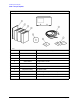
Installing Your Analyzer STEP 1. Verify the Shipment 3. Verify that all the accessories have been included with the analyzer.
Installing Your Analyzer STEP 2. Familiarize Yourself with the Analyzer Front and Rear Panels STEP 2. Familiarize Yourself with the Analyzer Front and Rear Panels Analyzer Front Panel CAUTION Do not mistake the line switch for the disk eject button. See the figure below. If the line switch is mistakenly pushed, the instrument will be turned off, losing all settings and data that have not been saved.
Installing Your Analyzer STEP 2.
Installing Your Analyzer STEP 3. Meet Electrical and Environmental Requirements STEP 3. Meet Electrical and Environmental Requirements 1. Set the line-voltage selector to the position that corresponds to the AC power source. 2. Ensure the available AC power source meets the following requirements: • 90–132 VAC • 47–66 Hz / 400 Hz (single phase) - or • 198–265 VAC • 47–66 Hz (single phase) The analyzer power consumption is 350 VA maximum. 3.
Installing Your Analyzer STEP 3. Meet Electrical and Environmental Requirements 5. Ensure there are at least six inches of clearance between the sides and back of either the stand-alone analyzer or the system cabinet. CAUTION The environmental temperature must be 4 °C less than the maximum operating temperature of the analyzer for every 100 watts dissipated in the cabinet. If the total power dissipated in the cabinet is >800 watts, then you must provide forced convection. 6.
Installing Your Analyzer STEP 4. Configure the Analyzer STEP 4. Configure the Analyzer This step shows you how to set up your particular analyzer configuration.
Installing Your Analyzer STEP 4. Configure the Analyzer To Configure the Standard Analyzer Connect test port cables and optional adapters if you are using other connector types. To Configure an Analyzer with a High Stability Frequency Reference (Option 1D5) Connect the jumper cable on the analyzer rear panel as shown.
Installing Your Analyzer STEP 4. Configure the Analyzer To Configure the Analyzer with Printers or Plotters 1. Connect your printer or plotter to the corresponding interface. 2. If you are using the parallel interface, press Local and toggle PARALLEL until your choice of COPY or GPIO appears. If you choose: Chapter 1 COPY the parallel port is dedicated for normal copy device use (printers or plotters). GPIO the parallel port is dedicated for general purpose I/O.
Installing Your Analyzer STEP 4. Configure the Analyzer 3. Press SET ADDRESSES . Then, depending on your printer/plotter device, choose either PRINTER PORT or PLOTTER PORT . Or, if you are plotting your files to disk, press SET ADDRESSES PLOTTER PORT DISK . 4. Press the key that corresponds to your printer or plotter interface: GPIB , PARALLEL (parallel port), or SERIAL (serial port). NOTE The plotter menu is shown as an example. It will only appear if you select PLOTTER PORT .
Installing Your Analyzer STEP 4. Configure the Analyzer 5. If you will be using the serial port, adjust the analyzer's baud rate until it is equal to the baud rate set on the peripheral by pressing PLOTTER BAUD RATE or PRINTER BAUD RATE and the and front panel keys. NOTE The plotter menu is shown as an example. It will only appear if you select PLOTTER PORT . You can set the analyzer to the following baud rates: • 1200 • 2400 • 4800 • 9600 • 19200 6.
Installing Your Analyzer STEP 4. Configure the Analyzer 7. If you will be creating a plot of the data, toggle PLTR TYPE until your choice of PLOTTER or HPGL PRT appears. • Choose PLOTTER for a pen plotter. • Choose HPGL PRT for a PCL5 compatible printer.1 8. If you will be using a printer, toggle PRNTR TYPE until your printer choice1 appears.
Installing Your Analyzer STEP 4. Configure the Analyzer 9. Press System SET CLOCK to begin setting and activating the time stamp feature so the analyzer places the time and date on your hardcopies and disk directories. 10. Press each of the following softkeys to set the date and time, followed by x1 . 11. Press ROUND SECONDS when the time is exactly as you have set it.
Installing Your Analyzer STEP 4.
Installing Your Analyzer STEP 4. Configure the Analyzer To Attach Front Handles to the Analyzer (Standard) 1. Ensure that the front handle kit is complete. 2. Remove the side trim strips. • (2) front handles • (6) screws • (2) trim strips NOTE If any items are damaged or missing from the kit, contact the nearest Agilent Technologies sales or service office to order a replacement kit. Items within the kit (handles, flanges, screws, etc.) are not individually available. 3.
Installing Your Analyzer STEP 4. Configure the Analyzer To Attach Cabinet Flanges without Front Handles to the Analyzer (Option 1CM) 1. Ensure that the cabinet flange kit is complete. 2. Remove side trim strips. • (2) cabinet mount flanges • (6) screws 3. Attach the cabinet flanges to the sides of the front panel using three screws for each flange. 1-18 4. Remove the feet and the tilt stands before cabinet mounting the instrument.
Installing Your Analyzer STEP 4. Configure the Analyzer To Attach Cabinet Flanges with Front Handles to the Analyzer (Option 1CP) 1. Ensure that the cabinet flange kit with handles is complete. 2. Remove the side trim strips. • (2) cabinet mount flanges • (2) front handles • (6) screws 3. Attach the cabinet mount flanges and the handles to the sides of the front panel, using three screws per side. (Attach the flanges to the outside of the handles.) WARNING Chapter 1 4.
Installing Your Analyzer STEP 5. Verify the Analyzer Operation STEP 5. Verify the Analyzer Operation The following procedures show you how to check your analyzer for correct operation: • viewing installed options • initiating self-test • running operator's check • testing transmission mode • testing reflection mode NOTE If the analyzer should fail any of the following tests, call the nearest Agilent Technologies sales or service office to determine the type of warranty you have.
Installing Your Analyzer STEP 5. Verify the Analyzer Operation To View the Installed Options 1. Cycle the AC power using the LINE switch, or press System FIRMWARE REVISION . SERVICE MENU 2. Locate the serial number and configuration options. Compare them to the shipment documents.
Installing Your Analyzer STEP 5. Verify the Analyzer Operation To Initiate the Analyzer Self-Test 1. Cycle the AC power using the LINE switch. 2.
Installing Your Analyzer STEP 5. Verify the Analyzer Operation To Run the Operator's Check 1. Connect the equipment as shown. 2. Press Preset System SERVICE MENU TESTS EXTERNAL TESTS EXECUTE TEST . Follow the prompts shown on the analyzer display and then press CONTINUE . 3. ET models only: Press EXECUTE TEST . Follow the prompts shown on the analyzer display and then press CONTINUE . 3. ES models only: Press EXECUTE TEST . Follow the prompts shown on the analyzer display and then press CONTINUE .
Installing Your Analyzer STEP 5. Verify the Analyzer Operation To Test the Transmission Mode 1. Connect the equipment as shown and press Preset . NOTE The test port return cable should have low-loss characteristics to avoid a degradation in frequency response at higher frequencies. 3. Look at the measurement trace displayed on the analyzer. It should be similar to the trace below. 1-24 2. Check the forward transmission mode for channel 2 by pressing Chan 2 Meas Trans: FWD S21(B/R) or TRANSMISSN . 4.
Installing Your Analyzer STEP 5. Verify the Analyzer Operation To Test the Reflection Mode 1. Connect the equipment as shown and press Preset . 2. Look at the measurement trace displayed on the analyzer. It should be similar to the trace below. 3. ES models only: Check the reverse reflection mode for channel 1 by pressing Meas Refl: REV S22 (B/R) . The measurement trace should be similar to the trace shown below. 4.
Installing Your Analyzer STEP 6. Back Up the EEPROM Disk STEP 6. Back Up the EEPROM Disk Description Correction constants are stored in EEPROM on the A9 controller assembly. The advantage of having an EEPROM backup disk is the ability to store all the correction-constant data to a new or repaired A9 assembly without having to rerun the correction-constant procedures. The analyzer is shipped from the factory with an EEPROM backup disk which is unique to each instrument.
Installing Your Analyzer STEP 6. Back Up the EEPROM Disk 5. Press FILE UTILITIES RENAME FILE ERASE TITLE . Use the front panel knob and the SELECT LETTER softkey to rename the file “FILE00” to “N12345” where 12345 represents the last 5 digits of the instrument's serial number. (The first character in the file name must be a letter.) When finished, press DONE . 6. Label the disk with the serial number of the instrument, the date, and the words “EEPROM Backup Disk.
2 Quick Start: Learning How to Make Measurements 2-1
Quick Start: Learning How to Make Measurements Introduction Introduction The information and procedures in this chapter teach you how to make measurements and what to do if you encounter a problem with your analyzer. The following sections are included: • Front Panel • Measurement Procedure • Learning to Make Transmission Measurements • Learning to Make Reflection Measurements • If You Encounter a Problem NOTE 2-2 The illustrations depicting the analyzer display were made using an ES model.
Quick Start: Learning How to Make Measurements Analyzer Front Panel Analyzer Front Panel CAUTION Do not mistake the line switch for the disk eject button. See the figure below. If the line switch is mistakenly pushed, the instrument will be turned off, losing all settings and data that have not been saved. Figure 2-1 The Analyzer Front Panel 1. LINE switch. This switch controls AC power to the analyzer. 1 is on, 0 is off. 2. Display.
Quick Start: Learning How to Make Measurements Analyzer Front Panel 9. ACTIVE CHANNEL keys. The analyzer has four independent display channels. These keys allow you to select the active channel. Then any function you enter applies to this active channel. Notice that the light next to the current active channel’s key is illuminated. 10. The ENTRY block. This block includes the knob, the step keys, and the number pad. These allow you to enter numerical data and control the markers.
Quick Start: Learning How to Make Measurements Measurement Procedure Measurement Procedure This is a general measurement procedure that is used throughout the guide to illustrate the use of the analyzer. Step 1. Choose measurement parameters with your test device connected • Press the Preset key to return the analyzer to a known state. • Connect your device under test (DUT) to the analyzer. CAUTION Damage may result to the DUT if it is sensitive to the analyzer's default output power level.
Quick Start: Learning How to Make Measurements Learning to Make Transmission Measurements Learning to Make Transmission Measurements This example procedure shows you how to measure the transmission response of a 175 MHz bandpass filter. The measurement parameters listed are unique to this particular test device. For further measurement examples, refer to the “Making Measurements” chapter in the User's Guide. Step 1. Choose the measurement parameters with your test device connected 1.
Quick Start: Learning How to Make Measurements Learning to Make Transmission Measurements Step 2. Perform a measurement calibration 1. Disconnect your test device from the analyzer. 2. Connect a “thru” between the measurement cables, as shown in Figure 2-3. Include all the adapters that you will use in your device measurement. If noise reduction techniques are needed for the measurement, the instrument's settings (reduced IF BW, and /or averaging) should be selected prior to any error-correction.
Quick Start: Learning How to Make Measurements Learning to Make Transmission Measurements Step 3. Measure the device Measuring Insertion Loss 1. Reconnect your test device as in Figure 2-2. 2. Reposition the measurement trace for the best view. This can be done by pressing Scale Ref AUTO SCALE and, if necessary, adjusting the reference level, reference position, or the scale/division. 3. Press Marker and turn the front panel knob to place the marker at a frequency of interest.
Quick Start: Learning How to Make Measurements Learning to Make Transmission Measurements Step 4. Output measurement results This example procedure shows how to output (store) measurement results to a disk. For more information on creating a hardcopy of the measurement results, refer to the "Printing, Plotting, and Saving Measurement Results" chapter in the User's Guide. CAUTION Do not mistake the line switch for the disk eject button.
Quick Start: Learning How to Make Measurements Learning to Make Transmission Measurements Measuring Other Transmission Characteristics Using the analyzer marker functions, you can derive several important filter parameters from the measurement trace that is shown on the analyzer display. Measuring 3 dB Bandwidth. The analyzer can calculate your test device bandwidth between two equal power levels.
Quick Start: Learning How to Make Measurements Learning to Make Transmission Measurements 5. Press WIDTH VALUE and enter −6 x1 . The analyzer now calculates the bandwidth between −6 dB power levels. 6. Press Marker Chapter 2 MARKER all OFF when you are finished with this measurement.
Quick Start: Learning How to Make Measurements Learning to Make Transmission Measurements Measuring Out-of-Band Rejection. 1. Press MARKER 1 . The marker appears where you placed it during the bandwidth measurement. 2. Press MKR ZERO Marker Search SEARCH: MIN . The marker automatically searches for the minimum point on the trace. The frequency and amplitude of this point, relative to the delta symbol in the center of the filter passband, appear in the upper-right corner of the display.
Quick Start: Learning How to Make Measurements Learning to Make Transmission Measurements Measuring Passband Flatness or Ripple. Passband flatness (or ripple) is the variation in insertion loss over a specified portion of the passband. Continue with the following steps to measure passband flatness or ripple. and 1. Press Save/Recall (if necessary, scroll to the desired file using the panel keys). Press RECALL STATE to recall the error-corrected transmission measurement that has no markers engaged.
Quick Start: Learning How to Make Measurements Learning to Make Reflection Measurements Learning to Make Reflection Measurements This example procedure shows you how to measure the reflection response of a 175 MHz bandpass filter. The measurement parameter values listed are unique to this particular test device. For further measurement examples, refer to the "Making Measurements" chapter in the User's Guide. NOTE Reflection measurements monitor only one port of a test device.
Quick Start: Learning How to Make Measurements Learning to Make Reflection Measurements Step 1. Choose measurement parameters with your test device connected 1. Press the Preset key to return the analyzer to a known state. 2. Connect your test device as shown in Figure 2-8. If using a load, make sure it has the correct characteristic impedance. Damage may result to the device under test if it is sensitive to the analyzer's default output power level.
Quick Start: Learning How to Make Measurements Learning to Make Reflection Measurements Step 2. Make a measurement calibration Follow these instructions to perform an S11 or reflection 1-port error correction: 1. Select a calibration kit that is appropriate to your device under test. Press Cal CAL KIT SELECT CAL KIT . Choose the calibration kit that is appropriate to your test device by pressing the appropriate softkey. For example, if your test device uses type-N 50Ω connectors, press N 50Ω .
Quick Start: Learning How to Make Measurements Learning to Make Reflection Measurements 6. Press SAVE STATE to complete the process. Step 3. Measure the device Measuring Return Loss. 1. Connect your device to PORT 1 or the REFLECTION port. 2. Press Scale Ref AUTO SCALE to reposition the trace. 3. Press Marker to read the return loss from the analyzer display as shown in Figure 2-10.
Quick Start: Learning How to Make Measurements Learning to Make Reflection Measurements Step 4. Output measurement results This step in the procedure shows you how to output the measurement results to a printer. For in-depth information on creating a hardcopy of the measurement results, refer to the “Printing, Plotting, and Saving Measurement Results” chapter in the User's Guide. 1. Connect a printer to the analyzer as described in “To Configure the Analyzer with Printers or Plotters” on page 1-11. 2.
Quick Start: Learning How to Make Measurements Learning to Make Reflection Measurements Measuring Other Reflection Characteristics You can derive several important filter parameters from the measurement shown on the analyzer display. The following set of procedures is a continuation of the previous reflection measurement procedure. Measuring Reflection Coefficient 1. Press Save/Recall RECALL STATE to recall the calibrated reflection measurement that you saved earlier in this procedure. 2.
Quick Start: Learning How to Make Measurements Learning to Make Reflection Measurements Measuring Standing Wave Ratio (SWR) Press Format SWR Scale Ref AUTO SCALE so the analyzer shows the same data in terms of standing-wave-ratio (SWR), as shown in Figure 2-13. Now the analyzer shows the measurement data in the unitless measure of SWR where SWR = 1 (perfect match) at the bottom of the display.
Quick Start: Learning How to Make Measurements Learning to Make Reflection Measurements Measuring S11 and S22 or Reflection in a Polar Format. 1. Press Format POLAR . 2. Press Scale Ref AUTO SCALE to reposition the trace, as shown in Figure 2-14. The analyzer shows the results of an S11 or reflection measurement with each point on the polar trace corresponding to a particular value of both magnitude and phase.
Quick Start: Learning How to Make Measurements Learning to Make Reflection Measurements Figure 2-14 Example S11 or Reflection Measurement Trace in Polar Format Measuring S11 and S22 or Reflection in a Smith Chart Format. • Measuring Impedance The amount of power reflected from a device is directly related to the impedance of the device and the measuring system.
Quick Start: Learning How to Make Measurements Learning to Make Reflection Measurements • Choose LIN MKR if you want the analyzer to show the linear magnitude and the phase of the reflection coefficient at the marker. • Choose LOG MKR if you want the analyzer to show the logarithmic magnitude and the phase of the reflection coefficient at the active marker. This is useful as a fast method of obtaining a reading of the log magnitude value without changing to log magnitude format.
Quick Start: Learning How to Make Measurements Learning to Make Reflection Measurements Figure 2-16 Example Admittance Measurement Trace 2-24 Chapter 2
Quick Start: Learning How to Make Measurements If You Encounter a Problem If You Encounter a Problem If you have difficulty when installing or using the analyzer, check the following list of commonly encountered problems and troubleshooting procedures. If the problem that you encounter is not in the following list, refer to additional troubleshooting sections in the Service Guide.
Quick Start: Learning How to Make Measurements If You Encounter a Problem If the display lights, but the ventilation fan does not start: ❏ Check that the fan is not obstructed. To check the fan, follow these steps: 1. Switch the LINE power to the off position. 2. Check that the fan blades are not jammed. ❏ Contact the nearest Agilent Technologies office for service, if necessary. A list of Agilent Technologies sales and service offices is provided in Table 2-1 on page 2-28.
Quick Start: Learning How to Make Measurements If You Encounter a Problem CAUTION If the error message: CAUTION: OVERLOAD ON INPUT X, POWER REDUCED appears on the analyzer display, too much source power is being applied at the input. In such a case, the input power will need to be reduced before the source power will remain on. ❏ If phase-lock error messages appear on the analyzer display, check that the front panel jumper is secure on the R CHANNEL connectors.
Quick Start: Learning How to Make Measurements If You Encounter a Problem Table 2-1 Agilent Technologies Sales and Service Offices UNITED STATES Instrument Support Center Agilent Technologies (800) 403-0801 EUROPEAN FIELD OPERATIONS Headquarters Agilent Technologies S.A. 150, Route du Nant-d’Avril 1217 Meyrin 2/ Geneva Switzerland (41 22) 780.
Index Numerics 3 dB bandwidth measuring, 2-10 6 dB bandwidth measuring, 2-11 A active channel keys location, 2-3 admittance measuring, 2-23 Agilent Technologies Sales and Service Offices, 2-28 analyzer configuration, 1-9–1-19 attaching cabinet flanges with front handles, 1-19 attaching cabinet flanges without front handles, 1-18 attaching front handles, 1-17 for bench top use, 1-16 for rack mount use, 1-16 option 1D5, 1-10 standard, 1-10 with printers or plotters, 1-11 B backing up EEPROM disk, 1-26 bench
Index measuring standing wave ratio (SWR), 2-20 measuring the device, 2-17 outputting measurement results, 2-18 REFLECTION port location, 2-4 requirements electrical and environmental, 1-7 response function block keys location, 2-3 Return key, location, 2-3 return loss measuring, 2-17 S Sales and Service Offices, 2-28 shipment, verifying, 1-3 smith chart, 2-22 smith chart format measuring, 2-22 softkeys, location, 2-3 standard analyzer configuration, 1-10 standing wave ratio (SWR) measuring, 2-20 stimulus