OPERATING GUIDE GPIB DC POWER SUPPLIES Agilent Technologies Models 664xA, 665xA, 667xA, and 668xA AGILENT Model 6641A: 3217A-00111 and Above * AGILENT Model 6642A: 3204A-00111 and Above * AGILENT Model 6643A: 3205A-00111 and Above * AGILENT Model 6644A: 3213A-00111 and Above * AGILENT Model 6645A: 3215A-00111 and Above * AGILENT Model 6651A: 3130A-00171 and Above * AGILENT Model 6652A: 3201A-00381 and Above * AGILENT Model 6653A: 3145A-00551 and Above * AGILENT Model 6654A: 3148A-00391 and Above * AGILENT
CERTIFICATION Agilent Technologies certifies that this product met its published specifications at time of shipment from the factory. Agilent Technologies further certifies that its calibration measurements are traceable to the United States National Bureau of Standards, to the extent allowed by the Bureau’s calibration facility, and to the calibration facilities of other International Standards Organization members.
SAFETY SUMMARY The following general safety precautions must be observed during all phases of operation, service, and repair of this instrument. Failure to comply with these precautions or with specific warnings elsewhere in this manual violates safety standards of design, manufacture, and intended use of the instrument. Agilent Technologies assumes no liability for the customer’s failure to comply with these requirements. BEFORE APPLYING POWER.
SAFETY SUMMARY (continued) GENERAL Any LEDs used in this product are Class 1 LEDs as per IEC 825-l. ENVIRONMENTAL CONDITIONS With the exceptions noted, all instruments are intended for indoor use in an installation category II, pollution degree 2 environment. They are designed to operate at a maximum relative humidity of 95% and at altitudes of up to 2000 meters. Refer to the specifications tables for the ac mains voltage requirements and ambient operating temperature range.
DECLARATION OF CONFORMITY according to ISO/IEC Guide 22 and EN 45014 Manufacturer’s Name: Agilent Technologies Inc. Manufacturer’s Address: 140 Green Pond Road Rockaway, New Jersey 07866 U.S.A.
DECLARATION OF CONFORMITY according to ISO/IEC Guide 22 and EN 45014 Manufacturer’s Name: Agilent Technologies Inc. Manufacturer’s Address: 140 Green Pond Road Rockaway, New Jersey 07866 U.S.A.
DECLARATION OF CONFORMITY according to ISO/IEC Guide 22 and EN 45014 Manufacturer’s Name: Agilent Technologies Inc. Manufacturer’s Address: 140 Green Pond Road Rockaway, New Jersey 07866 U.S.A.
DECLARATION OF CONFORMITY according to ISO/IEC Guide 22 and EN 45014 Manufacturer’s Name: Agilent Technologies Inc. Manufacturer’s Address: 140 Green Pond Road Rockaway, New Jersey 07866 U.S.A.
Table Of Contents 1 General Information Introduction ...................................................................................................................................................15 Safety Considerations................................................................................................................................16 Instrument Identification ...........................................................................................................................
4 User Connections Rear Panel Connections.................................................................................................................................57 Load Wire Selection ....................................................................................................................................57 Analog Connector........................................................................................................................................58 Digital Connector ..........
A Calibration Introduction ...................................................................................................................................................93 Equipment Required...................................................................................................................................93 General Procedure ......................................................................................................................................93 Parameters Calibrated......
F Using Agilent 668xA Series Power Supplies in Autoparallel Auto parallel Procedure...............................................................................................................................129 Index References ...................................................................................................................................................131 Agilent Sales and Support Offices Contacts.......................................................................................
List of Figures 2-1. 2-2. 2-3. 2-4. 2-5. 3-1. 4-1. 4-2. 4-3a. 4-3b. 4-3c. 4-3d. 4-3e. 4-3f. 4-3g. 4-4a. 4-4b. 4-4c. 4-4d. 4-4e. 4-4f. 4-4g. 4-5a. 4-5b. 4-5c. 4-5d. 4-5e. 4-5f. 4-5g. 4-6. 5-1. 5-2. A-l. A-2. B-l. C-l. C-2. C-3. C-4. C-5. D-1. D-2. D-3. D-4. D-5. D-6. E-l. E-2. F-1. Series 664xA/665xA Power Connection..................................................................................45 Connecting the Series 667xA Power Cord.......................................................................
List of Tables l-la. l-lb. 1-2a. 1-2b. 1-3a. 1-3b. 1-4a. 1-4b. 1-5. 1-6. 2-1. 3-1. 3-2. 3-3. 3-4. 4-1. 5-1. A-l. A-2. A-3. B-l. B-2. B-3. B-4. B-5. B-6. B-7. E-l. 14 Performance Specifications - Series 664xA.............................................................................20 Supplemental Characteristics - Series 664xA ..........................................................................21 Performance Specifications - Series 665xA.............................................................
1 General Information Introduction Two guides are shipped with your power supply - an Operating Guide (this document) and a Programming Guide.
Safety Considerations This power supply is a Safety Class 1 instrument, which means it has a protective earth terminal. That terminal must be connected to earth ground through a power source equipped with a 3-wire ground receptacle. Refer to the Safety Summary page at the beginning of this guide for general safety information. Before installation or operation, check the power supply and review this guide for safety warnings and instructions.
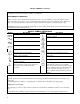
Option 909 909 910 ABD ABE ABF ABJ ABZ AB0 List of Options (continued) Description Used with Agilent Series 664xA 665xA 667xA 668xA Rack mount kit with handles (Agilent 5062-3975) x x x Rack mount kit with handles (Agilent 5062-3983) Support rails (E3663A) are required. Rack mount kit with handles (Agilent 5062-3983 & x 5062-3974) Support rails (E3663A) are required.
Operational features include: ■ ■ ■ ■ ■ ■ ■ ■ ■ ■ Constant voltage (CV) or constant current (CC) output over the rated output range. Built-in overvoltage (OV), overcurrent (OC), and overtemperature (OT) protection. Automatic turn-on selftest. Pushbutton nonvolatile storage and recall of up to 5 operating states (4 in Series 668xA supplies). Local or remote sensing of output voltage. Auto-parallel operation for increased total current. Series operation for increased total voltage.
Output Characteristic General The power supply can operate in either CV (constant voltage) or CC (constant current) over its voltage and current ratings (see Table 1-l). The operating locus is shown by the Output Characteristic Curve in Table 1-2. The operating point is determined by the voltage setting (Vs), the current setting (Is), and the load impedance. Two operating points are shown. Point 1 is defined by the load line cutting the operating locus in the constant-voltage region.
1 Table 1-1a. Performance Specifications for Series 664xA Parameter Agilent Model Number 6641A 6642A 6643A 6644A Output Ratings Voltage: 0-8V 0 - 20 V 0 - 35 V 0 - 60 V 0 - 20 A 0 - 10 A 0-6A 0 - 3.5 A Current:@ 40°C 0 - 18 A 0-9A 0 - 5.4 A 0 - 3.2 A Current:@ 50°C 0 - 17 A 0 - 8.5 A 0 - 5.1 A 0 - 3.0 A Current:@ 55°C 6645A 0 - 120 V 0 - 1.5 A 0 - 1.4 A 0 -1.4 A Programming Accuracy (@ 25 ± 5 °C) Voltage: 0.06% + 5 mV 10 mV 15 mV 26 mV 51 mV Current: 26 mA 13 mA 6.7 mA 4.1 mA 1.7 mA 0 .
1 Table 1-1b. Supplemental Characteristics for Series 664xA Parameter Agilent Model Number 6641A 6642A 6643A 6644A Output Programming Range (maximum programmable values) 6645A Voltage: Current: Overvoltage Protection (OVP): 8.190 V 20.475 A 8.8 V 20.475 V 10.237 A 22.0 V 35.831 V 6.142 A 38.5 V 61.425 V 3.583 A 66.0 V 122.85 V 1.535 A 132.0 V Average Resolution Voltage: Current: Overvoltage Protection (OVP): 2 mV 6 mA 13 mV 5 mV 3 mA 30 mV 10 mV 2 mA 54 mV 15 mV 1.2 mA 93 mV 30 mV 0.
1 Table 1-lb. Supplemental Characteristics for Series 664xA (continued) Parameter Agilent Model Number 6641A 6642A 6643A 6644A 6645A Maximum AC Line Current Ratings 100 Vac nominal: 4.4 A rms 120 Vac nominal: 3.8 A rms 220 Vac nominal: 2.2 A rms 230 Vac nominal: 2.1 A rms 240 Vac nominal: 2.
1 Table 1-1b. Supplemental Characteristics for Series 664xA (continued) Parameter All Models (see Table 1-5) Digital Port Characteristics GPIB Interface Capabilities (see Table 1-5) Serial Link Capabilities (see Table 1-5) 1 year Recommended Calibration Interval: Safety Compliance Complies with: Designed to comply with: CSA 22.2 No.
1 Table 1-1b. Supplemental Characteristics for Series 664xA (continued) Parameter All Models Output Impedance Curves (Typical): Notes: lFor Performance Specifications, see Table l-la.
1 Table 1-2a. Performance Specifications for Series 665xA Parameter Agilent Model Number 6651A 6652A 6653A 6654A Output Ratings Voltage: 0-8V 0 - 20 V 0- 35 V 0 - 60 V 0 - 50 A 0 - 25 A 0 - 15 A 0-9A Current:@ 40°C 0 - 45 A 0 - 22.5 A 0 - 13.5 A 0 - 8.1 A Current:@ 50°C 0 - 42.5 A 0 - 21.3 A 0 - 12.8 A 0 - 7.7 A Current:@ 55°C 6655A 0 - 120 V 0-4A 0 - 3.6 A 0 -3.4 A Programming Accuracy (@ 25 ± 5 °C) Voltage: 0.06% + 5 mV 10 mV 15 mV 26 mV 51 mV Current: 60 mA 25 mA 13 mA 8 mA 4 mA 0 .
1 Table 1-2b. Supplemental Characteristics for Series 665xA Parameter Agilent Model Number 6651A 6652A Output Programming Range (maximum programmable values) 6653A 6654A 6655A Voltage: Current: Overvoltage Protection (OVP): 8.190 V 51.188 A 8.8 V 20.475 V 25.594 A 22.0 V 35.831 V 15.356 A 38.5 V 61.425 V 9.214 A 66.0 V 122.85 V 4.095 A 132.0 V Average Resolution Voltage: Current: Overvoltage Protection (OVP): 2 mV 15 mA 13 mV 5 mV 7 mA 30 mV 10 mV 4 mA 54 mV 15 mV 2.
1 Table 1-2b. Supplemental Characteristics for Series 665xA (continued) Parameter Agilent Model Number 6651A 6652A 6653A 6654A 6655A Maximum AC Line Current Ratings 100 Vac nominal: 12 A rms (15 AM fuse) 120 Vac nominal: 10 A rms (12 AM fuse) 220 Vac nominal: 5.7 A rms (7 AM fuse) 230 Vac nominal: 5.5 A rms (7 AM fuse) 240 Vac nominal: 5.
1 Table 1-2b. Supplemental Characteristics for Series 665xA (continued) Parameter All Models (see Table 1-5) Digital Port Characteristics GPIB Interface Capabilities (see Table 1-5) Serial Link Capabilities (see Table 1-5) 1 year Recommended Calibration Interval: Safety Compliance Complies with: Designed to comply with: CSA 22.2 No.
1 Table 1-2b. Supplemental Characteristics for Series 665xA (continued) Parameter All Models Output Impedance Curves (Typical): Notes: lFor Performance Specifications, see Table l-2a.
1 Table 1-3a. Performance Specifications for Series 667xA Parameter Agilent Model Number 6671A 6672A 6673A 6674A Output Ratings Voltage: 0-8V 0 - 20 V 0- 35 V 0 - 60 V 0 - 220 A 0 - 100 A 0 - 60 A 0 - 35 A Current:@ 0 to 55°C Programming Accuracy (@ calibration temperature* ± 5 °C) 6675A 0 - 120 V 0 - 18 A Voltage: 0.04% + 8 mV 20 mV 35 mV 60 mV 120 mV Current: 0.
1 Table 1-3b. Supplemental Characteristics for Series 667xA Parameter Agilent Model Number 6671A 6672A Output Programming Range (maximum programmable values) 6673A 6674A 6675A Voltage: Current: Overvoltage Protection (OVP): 8.190 V 225.23 A 10.0 V 20.475 V 102.37 A 24.0 V 35.831 V 61.43 A 42.0 V 61.425 V 35.83 A 72.0 V 122.85 V 18.43 A 144.0 V Typical Resolution Voltage: Current: Overvoltage Protection (OVP): 2 mV 55 mA 15 mV 5 mV 25 mA 35 mV 10 mV 15 mA 65 mV 15 mV 8.75 mA 100 mV 30 mV 4.
1 Table 1-3b. Supplemental Characteristics for Series 667xA (continued) Parameter Agilent Model Number 6671A 6672A 6673A 6674A 6675A Remote Sensing Capability Voltage Drop Per Lead: Up to 1/2 of rated output voltage. Load Voltage: Subtract voltage drop in load leads from specified output voltage rating.
1 Table 1-3b. Supplemental Characteristics for Series 667xA (continued) Parameter All Models (see Table 1-5) Digital Port Characteristics GPIB Interface Capabilities (see Table 1-5) Serial Link Capabilities (see Table 1-5) 1 year Recommended Calibration Interval: Safety Compliance Complies with: Designed to comply with: CSA 22.2 No.
1 Table 1-3b. Supplemental Characteristics for Series 667xA (continued) Parameter All Models Output Impedance Curves (Typical): Notes: lFor Performance Specifications, see Table l-3a.
1 Table 1-4a. Performance Specifications for Series 668xA Parameter Agilent Model Number 6680A 6681A 6682A 6683A Output Ratings Voltage: 0-5V 0-8V 0- 21 V 0 - 32 V Current:* 0 - 875 A 0 - 580 A 0 - 240 A 0 - 160 A *Derated linearly 1%/°C from 40 ° C to 55 °C Programming Accuracy (@ 25 ± 5 °C) 6684A 0 - 40 V 0 - 128 A Voltage: 0.04% + 5 mV 8 mV 21 mV 32 mV 40 mV Current: 0.
1 Table 1-4b. Supplemental Characteristics for Series 668xA Parameter Agilent Model Number 6680A 6681A Output Programming Range (maximum programmable values) 6682A 6683A 6684A Voltage: Current: Overvoltage Protection (OVP): 5.125 V 895 A 6.25 V 8.190 V 592 A 10.0 V 21.50 V 246 A 25.2 V 32.75 V 164 A 38.4 V 41.0 V 131 A 48.0 V Typical Resolution Voltage: Current: Overvoltage Protection (OVP): 1.35 mV 235 mA 30 mV 2.15 mV 155 mA 45 mV 5.7 mV 64 mA 120 mV 8.6 mV 43 mA 180 mV 10.
1 Table 1-4b. Supplemental Characteristics for Series 668xA (continued) Parameter Agilent Model Number 6680A 6681A 6682A 6683A Remote Sensing Capability Voltage Drop Per Lead: Up to 1/2 of rated output voltage. Load Voltage: 6684A Subtract voltage drop in load leads from specified output voltage rating.
1 Table 1-4b. Supplemental Characteristics for Series 668xA (continued) Parameter All Models Command Processing Time (Average time for output voltage to change after receipt of digital data when the supply is connected directly to the GPIB Bus): 20 ms Monotonicity: Output is monotonic over entire rated voltage, current, and temperature range.
1 Table 1-4b. Supplemental Characteristics for Series 668xA (continued) Parameter All Models Output Impedance Curves (Typical): CV MODE CV MODE CC MODE 20 CC MODE * 20 * 10 OUTPUT IMPEDANCE (MILLIOHMS) OUTPUT IMPEDANCE (MILLIOHMS) 10 5 ** 2.5 1.25 0.625 0.312 0.156 0.078 0.039 5 ** 2.5 1.25 0.625 0.312 0.156 0.078 0.039 0.0195 100 30 0.
Table 1-5. Supplemental GPIB Characteristics For All Models Parameter All Models Digital Port Characteristics Maximum ratings: 16.
Table 1-6. Operator Replaceable Parts List Description Agilent Part No. (Unless otherwise specified, parts apply to all models.
Table 1-6. Operator Replaceable Parts List (continued) Description Agilent Part No. (Unless otherwise specified, parts apply to all models.) Screw, output bus bar Series 665xA only Series 667xA only, 1/4-20x1/2 Screw, outer cover, M5 x 0.8 mm Screw, output sense terminal, M3x0.
2 Installation Inspection Damage When you receive your power supply, inspect it for any obvious damage that may have occurred during shipment. If there is damage, notify the shipping carrier and the nearest Agilent Sales and Support Office immediately. Warranty information is printed in the front of this guide. Packaging Material Until you have checked out the power supply save the shipping carton and packing materials in case the power supply has to be returned to Agilent Technologies.
Output hardware Table 2-1. Items Supplied (continued) Series 667xA only Output hardware (screws with nuts and lockwashers) for securing your load wires to the output bus bars (see Table 1-6). Pack return system Series 668xA Only (Agilent P/N 5080-2430). Materials and instructions for properly disposing of the shipping carton and packing materials. Guide change page If applicable, change sheets may be included with this guide. If there are change sheets, make the indicated corrections in this guide.
INPUT POWER SOURCE Refer to the applicable paragraphs below for information on the input power source. Do not apply power to the power supply until directed to do so in Chapter 3. Check the line label on the rear of your supply and verify that the voltage shown there corresponds to the nominal line voltage of your power source. If it does not, see "Appendix C - Line Voltage Conversion" for instructions on changing the power supply’s line voltage configuration.
Installing the Power Cord Installation of the power cord must be done by a qualified electrician and in accordance with local electrical codes. The power cord supplied with power supply may or may not include a power plug (see "Options" in Chapter l) at one end of the cord. Terminating connections and a ground lug are attached to the other end of the cord. See Figure 2-2 and proceed as follows: 1.
Figure 2-3. 667xA Connection to a 3-Phase Line Series 668xA Supplies Line Wiring The power supply requires a 3-phase power source that provides 7350 VA (6000 W) maximum. The power supply has a delta input (no neutral connection) and will accept power from either delta (triangle) or wye (star) sources. Two voltage ranges are available (see "AC Input Ratings" in Table 1-4a).
Installing the Power Cord Installation of the power cord must be done by a qualified electrician and in accordance with local electrical code The power cords supplied with the power supply do not include a power plug (see "Options" in Chapter l) at one end of the cord. Terminating connectors and a ground lug are attached to the other end of the cord. See Figure 2-5 and proceed as follows: l. Check the line fuses ( , Figure 2-5) as follows: a. Examine the label on the rear panel. b.
3 Turn-On Checkout Note This chapter provides a preliminary introduction to the power supply front panel. See "Chapter 5 - Front Panel" for more details. Introduction Successful tests in this chapter provide a high degree of confidence that the power supply is operating properly. For verification tests, see “Appendix B - Operation Verification”. Complete performance tests are given in the service manual (see Table 1-5 in Chapter 1). Do not apply ac power to the power supply until told to do so.
Power-On Checkout (All Models) 1. Connect the power cord to the power source (for Series 668xA, turn on the safety disconnect switch). 2. Turn the front panel power switch to ON (1). 3. For Series 668xA only, the Check Fuses and Dew LEDs should remain off. If either light is on or is blinking, go to “In Case of Trouble” at the end of this chapter. 4. The power supply undergoes a self-test when you turn it on. If the test is normal, the following sequence appears on the LCD: a.
Checking the Voltage Function (All Models) The tests in Table 3-1 check the basic voltage functions with no load connected to the power supply. The VOLTS display will show various readings. Ignore the AMPS display. Table 3-1. Checking the Voltage Functions (Output Terminals Open) Display Explanation Output Terminals Open or Connected to a Voltmeter If Dis is on, turn it off by pressing Press key VOLT 0.000 Default voltage setting. CV annunciator should be on.
Checking the Current Function ENERGY HAZARD. Some supplies (Series 668xA) can provide more than 240 VA at more than 2 V. If the output connections touch, severe arcing may occur resulting in burns, ignition or welding of parts. Do not attempt to make connections while the output is live. The tests in Table 3-2 check the basic current functions with a short connected across the power supply output.
Table 3-2. Checking the Current Functions (Output Terminals Shorted) (continued) Action Display Explanation AMPS 0.000 Press Dis annunciator turns on. Press You have disabled the overcurrent protection circuit. The OCP annunciator turns off. Press ( You have cleared the overcurrent protection circuit. The Prot annunciator turns off. )** AMPS 1.000 Press Dis turns off and CC turns on. The output current is restored.
Series 664xA and 665xA Supplies The line fuse is located on the rear panel (3, Figure 2-l). Proceed as follows: 1. Turn off the front panel power switch. 2. Using a screwdriver, remove the fuse from the fuseholder. Replace it with one of the same type (see Table 1-5 in Chapter l). Do not use a time-delay type fuse. 3. Turn on the power supply and check the operation. Series 667xA Supplies Hazardous voltage can remain inside the power supply even after it has been turned off.
Series 668xA Supplies The line fuses are located on the rear panel (see Figure 2-4). Proceed as follows: l. Turn off the front panel power switch and remove the input power (unplug the power cord or open the safety disconnect). 2. Remove the ac input safety cover from the rear panel. 3. Unscrew the fuse caps and remove the fuses. 4. If one or two fuses are defective, replace all three with fuses of the same type (see Table 1-5 in Chapter l).
Checksum Errors. If the display shows EE CHKSUM, the power supply has detected an EEPROM checksum error. A checksum error can occur due to the following conditions: ■ ■ Excessive number of write cycles to an EEPROM (see "Nonvolatile Memory Write Cycles" in "Supplemental Characteristics" tables). This condition, which would appear only after extended use, is not recoverable and requires service. Loss of ac input power during a checksum calculation. This condition, which is very unlikely, is recoverable.
4 User Connections Rear Panel Connections (All Models) Make application load connections to the output terminals or bus bars, analog connector, and digital connector as shown on the rear-panel drawing for your model power supply. These connections are organized by series as follows: l Series 664xA and 665xA l Series 667xA l Series 668xA Make controller connections (GPIB and serial link) as shown in Figure 4-6 at the end of this chapter.
Analog Connector (All Models) This connector, which is on the rear panel, is for connecting remote sense leads, external current monitors, and external programming sources. The connector accepts wires sizes from AWG 22 to AWG 12. ó Tighten Screws Agilent Series 667xA & 668xA IM Current monitor output. VP Voltage programming input. +IP Differential current programming input. --IP Differential current programming input. ↓P Common for VP and IM signals 1. +S + remote sense input. --S -remote sense input.
Connecting Series 664xA and 665xA Power Supplies To The Load Output Safety Cover ó + Output Terminal ì - Output Terminal öSignal Common ú Output Sense Switch ÷ Analog Connector Figure 4-3a. Series 664xA and 665xA Rear Panel Output Connections Output Isolation The output of the power supply is isolated from earth ground. Either output terminal may be grounded, or an external voltage source may be connected between either output and ground.
Series 664xA/665xA Power Supplies, Maximum OVP External Capacitance (µF) 6641A 700,000 6642A 35,000 6643A 15,000 6644A 7,000 6645A 3,000 6651A 1.6 (F) 6652A 100,000 6653A 50,000 6654A 18,000 6655A 8,000 If a load capacitance approaches the specified limit, it is recommended that you do not make it a normal practice of tripping the OVP circuit and discharging the load capacitance through that circuit. This could cause long-term fatigue in some circuit components.
Note If the sense terminals are left unconnected, the voltage at the bus bars will increase approximately 3 to 5% over the programmed value. Since it is measured at the sense terminals, the voltage readback will not reflect this increased output. Remote Voltage Sensing The dashed lines in the wiring diagrams illustrate remote voltage sensing. The remote sense terminals of the power supply are connected directly to the load rather than to the output terminals.
Stability Using remote sensing under unusual combinations of load-lead lengths and large load capacitances may cause your application to form a low-pass filter that becomes part of the voltage feedback loop. The extra phase shift created by this filter can degrade the supply’s stability and result in poor transient response. In severe cases, this may cause output oscillations. To minimize this possibility, keep the load leads as short as possible and tie wrap them together.
Load Connection ó Loads A Set switch for local or (optional) remote sensing ì Analog Connector B Connect for remote sensing (optional) Figure 4-3c. Series 664xA and 665xA Multiple Load Connection (Remote Sensing Optional) Connecting Supplies in Auto-Parallel Auto-Parallel Wiring. Figure 4-3d illustrates how power supplies can be connected in auto-parallel for increased current output. You can connect up to three supplies of the same model .
Auto-Parallel Programming. Program only the first ("master") supply in the series; the "slave" supplies automatically track the master’s output. However, the voltage and OVP settings of the slave supplies must be set higher than the operating voltage of the master supply. This ensures that the slave supplies will operate in CC mode. Functions such as status, voltage readback, and current readback can still be read back individually for each supply.
Connecting Supplies in Series Floating voltages must not exceed ±240 Vdc. No output terminal may be more than 240 V from chassis ground. Figure 4-3f shows how power supplies can be connected in series for higher voltage output. Series connections are straightforward in this case. Program each power supply independently. If two supplies are used in the series configuration, program each supply for 50% of the total output voltage.
Be careful of capacitive coupling from the programming inputs to other lines wired to the analog connector. Such coupling can cause output oscillations. You can minimize coupling by bundling the IP, VP, and Common P lines and keeping them separated from other wires. Twisting these three lines together is also recommended. Analog connector l=Voltage programming source 0 to--5 V 2=Current programming source 0 to +10 V Figure 4-3g.
Output Safety Cover ó Analog Connector ì-Output Bus Bar ö-Local Sense Terminal ú + Local Sense Terminal ÷+ Output Bus Bar ø Signal Common í Local Sense Jumpers û Rear Knockouts ç Bottom Knockout A Insert screwdriver blade in slot and pry out B Bend along joint and break off WARNING DO NOT LEAVE UNCOVERED HOLES IN OUTPUT COVER. IF TOO MANY KNOCKOUTS HAVE BEEN REMOVED, INSTALL A NEW COVER. Figure 4-4a.
Q= 1 R int + Re xt L C where: C = model-dependent internal capacitance (see below); L = inductance of the load; Rext = equivalent series resistance of the load; Rint = model-dependent internal resistance (see below): 6671A 44,000 µF 1.8 mΩ C= Rint= 6672A 44,000 µF 2.2 mΩ 6673A 12,000µF 4 mΩ 6674A 7,000 µF 14 mΩ 6675A 2,100 µF 30 mΩ If the Q is greater than 0.
Connecting the Sense Leads You must connect the positive side of the load to the +S analog connector pin and the negative side of the load to the -S analog connector pin (see Figure 4-1). Connect the sense leads carefully so that they do not become open-circuited. If sense leads are left open during operation, the supply will regulate at the output terminals instead of at the load. Remember to bundle or tie wrap the load leads to minimize inductance and reduce noise pickup.
Load Leads Cl, C2 = 33 µF óRemote Sense Points C3 = Load bypass capacitor R1, R2 = 20 Ω, 1% Figure 4-4b. Series 667xA Sense Lead Bypass Network Operating Configuration Figure 4-4c through Figure 4-4f show the various configurations for connecting to the load. Figure 4-4g shows how to connect an external voltage source for analog programming. Connecting One Power Supply to a Single Load (Figure 4-4c) Figure 4-4c shows how to connect a single power supply to one load.
Loads óLoad Connection ìAnalog Connector A Connect for remote sensing (optional) Connect for local sensing (default) B Figure 4-4d. Series 667xA Multiple Load Connection (Remote Sensing Optional) Connecting Supplies in Auto-Parallel Auto-Parallel Wiring (Figure 4-4e). Figure 4-4e illustrates how power supplies can be connected in auto-parallel for increased current output. You can connect up to five supplies of the same model.
Auto-Parallel Programming. Program only the first ("master") supply in the series; the "slave" supplies automatically track the master’s output. However, the voltage and OVP settings of the slave supplies must be set higher than the operating voltage of the master supply. This ensures that the slave supplies will operate in CC mode. Functions such as status, voltage readback, and current readback can still be read back individually for each supply.
External Voltage Control The setup shown in Figure 4-4g allows an external dc voltage to program the power supply output. A voltage applied to the voltage programming input programs the output voltage and a voltage applied to the current programming input programs the output current. See Figure 4-1 for an explanation of these programming input connections. Wiring Considerations (Figure 4-4g) The input impedance of the analog input is over 30 kΩ.
Connecting Series 668xA Power Supplies To The Load ENERGY HAZARD. These power supplies can provide more than 240 VA at more than 2 V. If the output connections touch, severe arcing may occur resulting in burns, ignition or welding of parts. Do not attempt to make connections to live output circuits. Analog Connector ó -Output Bus Bar ì -Local Sense Tap ö + Output Bus Bar ú + Local Sense Tap ÷ Signal Common A Option 601 cover required for bench installation Figure 4-5a.
Inductive Loads Inductive loads present no loop stability problems in CV mode. In CC mode, inductive loads will form a parallel resonance with the power supply’s output capacitor, possibly causing current ringing in the load. For a given inductance, the power supply’s CC control loop can be made to stabilize the current. However, stabilizing the current for a very large load inductance creates a much slower mode crossover (CV to CC or vice versa) time.
OVP Considerations The power supply OVP circuit senses voltage near the output bus bars, not at the load. Therefore the signal sensed by the OVP circuit can be significantly higher than the actual voltage at the load. When using remote sensing, you must program the OVP trip voltage high enough to compensate for the voltage drop between the output bus bars and the load. Output Rating In remote sense applications, the voltage drop in the load leads subtracts from the available load voltage.
Connecting One Power Supply to a Single Load Figure 4-5c shows how to connect a single power supply to one load. Keep output load leads close together (small loop area) to obtain a low inductance and low impedance connection to the load. If you wish to use remote sensing, connect the sense leads at the load as shown in the figures.
Connecting Supplies in Auto-Parallel Auto-Parallel Wiring (Figure 4-5e). Figure 4-5e shows how power supplies can be auto-paralleled for increased current output. Up to three supplies can be connected for auto-parallel operation. Use heavy enough load leads so that the absolute voltage difference between the ⊕ output terminals of the "master" supply and the ⊕ output terminal of the first "slave" supply is kept under 2 V at rated current.
Program each power supply as an independent supply. If two supplies are used in series operation, each supply can be programmed to deliver 50% of the total output voltage. Set the current limit of each power supply to the maximum that the load can handle without damage. If one supply experiences a desired shutdown condition (such as caused by overtemperature or overcurrent), it does not automatically shut down the other supply.
1 = Voltage programming source 0 to -5 V 2 = Current programming source 0 to +5 V 3 = Current programming source 0 to -5 V 4 = Current programming source floating 0 to 5 V * Maximum potential between -IP and ↓P or between +IP and ↓P is ±15 V Figure 4-5g. Series 668xA Analog Programming Connections Programming Note from Figure 4-1 that you have three options for programming the current. You can use a voltage source that is positive, negative, or floating with respect to Common P.
The first power supply in a linked connection is a "direct supply" connected to the controller via a GPIB cable. The direct supply is the only supply connected directly to the bus and has a unique primary bus address. ■ The remaining power supplies are "linked supplies” connected to the direct supply via a serial-link cable. Each linked supply has a unique secondary GPIB address and derives its primary address from the direct supply. You may connect from 1 to 15 linked supplies to each direct supply.
5 Front Panel Operation Introduction This chapter shows you how to operate the front panel. It is assumed that you are familiar with the turn-on checkout procedure in Chapter 3. That chapter describes how to perform basic power supply functions from the control panel. operations that you can perform are: ■ ■ ■ ■ ■ ■ ■ ■ ■ ■ Enabling or disabling the power supply output. Setting the output voltage and current. Monitoring the output voltage and current. Setting the overvoltage protection (OVP) trip point.
Figure 5-1. Front Panel Controls and Indicators Control or Indicator Table 5-1. Front Panel Controls and Indicators (see Figure 5-1) Function or Indication Display VOLTS AMPS CV CC Unr Dis OCP Prot Err Cal Shift Rmt Addr SRQ Shows present output voltage of the power supply. Shows present output current of the power supply. Status Annunciators The power supply is in constant-voltage mode. The power supply is in constant-current mode. The power supply output is unregulated (output is neither CV or CC).
Voltage Current Table 5-1. Front Panel Controls and Indicators (continued) óOutput Rotary Controls Rotate clockwise to increase output voltage or program setting. Use to rapidly set an approximate output and keys). value (see Rotate clockwise to increase output current or program setting. Use to rapidly set an approximate current and keys). value (see ì SYSTEM Keys When the power supply is under remote control, press to enable local operation.
thru Table 5-1. Front Panel Controls and Indicators (continued) ú ENTRY Keys (continued) Press to select numerical values . Press to enter a minus sign. Press to delete the last keypad entry. Use this key to remove one or more incorrect digits before they are entered. 3 These four entry keys operate in two modes. Press and release for a single minimal change as determined by the programming resolution (see Table 1-2 in Chapter l). Press and hold for an increasingly rapid output change.
Figure 5-2. Typical Power Supply Operating Curve Programming Voltage To program the output for 4.5 volts, proceed as follows: ■ ■ ■ ■ Press . The display will change from meter mode to indicate VOLTS. Press . If you discover a mistake before pressing , erase the incorrect value with the backspace key . The display will return to the meter mode and indicate 0.000 volts. to enable the output (Dis annunciator turns off). The VOLTS display will indicate 4.500 volts.
Checking OVP Operation Assuming the above operating conditions (voltage programmed to 4.5 V and OVP programmed to 4.8 V), trip the OVP circuit as follows: Gradually increase the output voltage by pressing until the OVP circuit trips. This will cause the output voltage to drop to zero and the Prot annunciator to go on. ■ There now is no power supply output due to an overvoltage condition. ■ To verify this, press and observe that the display indicates 0V.
Programming Overcurrent Protection When enabled, overcurrent protection removes the power supply output whenever it goes into CC operation. This prevents the supply from indefinitely supplying the full programmed current to the load. Setting The OCP Protection To activate overcurrent protection, press . The OCP annunciator will light and power supply will continue to operate normally until it is forced into CC operation. If that occurs, the OCP circuit will trip and the power supply will remove its output.
Unregulated Operation If the power supply goes into a mode of operation that is neither CV nor CC, the Unr annunciator will light. An unregulated condition limits the output current to a value that is safe for the power supply. Some unregulated states occur so briefly that they do not turn on the Unr annunciator, but they may set the UNR status bit during remote operation (see the power supply “Programming Guide”). One condition that can cause a noticeable unregulated state is low ac line voltage.
Whenever you wish, you can return the power supply to the original factory reset state. To do this, simply hold down the key when you turn on the supply. The display indicates RST POWER-ON to verify that the power supply has configured its turn-on state to the original reset state. From now on it will continue to turn on in that state. Setting The GPIB Address Types of Power Supply GPIB Addresses Figure 4-6 in Chapter 4 shows the ways the power supply can be connected to the GPIB bus.
A Calibration Introduction The power supply may be calibrated either from the front panel or from a controller over the GPIB. The procedures given here apply to all models. Important These instructions do not include verification procedures. If you need to perform verification as a erequisite to or as part of your calibration procedure, see “Appendix B - Verification”. Equipment Required The equipment listed in Table A-1, or equivalent, is required for calibration. Equipment Table A-1.
• • • Output current. Output current readback. Current monitor input IM (Series 668xA only). You do not have to do a complete calibration each time. If appropriate, you may calibrate only the voltage or current and proceed to "Saving the Calibration Constants". However, for Series 668xA supplies, the following sequences must be followed: • • Calibrate voltage before OVP. Calibrate the current monitor input before current output.
Figure A-1.
Table A-2. Typical Front Panel Calibration Procedure Action Enabling the Calibration Mode 1. Begin calibration by pressing . 2. Enter calibration password from Entry keypad. If password is correct the Cal annunciator will come on. If password is incorrect, an error occurs 2. Note: The initial (factory-default) password is the model number of the power supply, but it can be changed (see "Changing the Password" in Appendix A - Calibration). Entering Voltage Calibration Values 1.
Table A-2. Typical Front Panel Calibration Procedure (continued) Action Display Response Calibrating Current Monitor (IM) (Series 668xA Only) If you perform this calibration, then you must recalibrate the current output. 1. Make certain the appropriate shunt resistor (see Table A-1) is the only load on the power supply. 2. Select IMN calibration by pressing If the power supply is not in CC mode, an error occurs.4 3. Wait for DVM reading to stabilize.
Calibration Over The GPIB You can calibrate the power supply by using SCPI commands within your controller programming statements. Be sure you are familiar with calibration from the front panel before you calibrate from a controller.
CAL:CURR:MON (Series 668xA only) This command sets the power supply to the current monitor (IMON) calibration point that is then entered with CAL:CURR[:DATA]. The output current must be calibrated after CAL:CURR:MON is performed. Command Syntax Parameters Examples Query Syntax Related Commands CALibrate:CURRent:MONitor CAL: CURR: MON CALibrate: CURRent: MONitor (None) CAL:CURR[:DATA] CAL:STAT CAL:PASS This command enters a new calibration password.
CAL:VOLT This command is used to calibrate the output voltage. The command enters voltage value that you obtain from an external meter. (If you are entering the voltage value, allow time for the DVM to stabilize.) You must first select a calibration level (CAL:VOLT:LEV) for the value being entered. Two successive values (one for each end of the calibration range) must be selected and entered. The power supply then computes new voltage calibration constants.
10 ! Agilent BASIC Calibration Program 20 ! 30 DIM Resp$ [255],Err_msg$[255] 40 ! 50 Volt_cal: ! Voltage DAC calibration 60 Err_found=0 70 PRINT TABXY(5,10),"CONNECT INSTRUMENTS AS SHOWN IN FIG. A -1(1).
540 550 560 570 580 590 600 610 620 630 Password is optional - only required if set to non-zero value Default password is four-digit model number ! ! LINE 590 PASSWORD MUST BE EDITED FOR MODEL OTHER THAN 6680 ! OUTPUT @Ps;"CAL:STATE ON, 6680" OUTPUT @Ps;"VOLT:LEV 2" ! Refer to Table A-1 for correct shunt value for model being calibrated ! INPUT "ENTER VALUE 0F CURRENT SHUNT BEING USED",Shunt_val STEPS 640 THROUGH 670 NOT USED ON 664x, 665x and 667x 640 OUTPUT @Ps;"CAL:CURRENT:MONITOR" 650 INPUT "ENTER VOLT
B Operation Verification Introduction This appendix provides operation verification test procedures. The tests do not check all the operating parameters, but verify that the power supply is performing properly. The required test equipment and acceptable test results are specified in tables at the end of this appendix. Note Performance Tests, which check all the specifications of the power supply, are given in the applicable power supply Service Manual.
Figure B-1.
Performing The Tests General Measurement Techniques Figure B-1 shows the setup for the tests. Be certain to use load leads of sufficient wire gauge to carry the output current (see Table 4-1). To avoid noise pickup, use coaxial cable or shielded pairs for the test leads. Programming the Power Supply Table 1-lb, Table 1-2b, Table 1-3b and Table 1-4b in Chapter 1 list the programming voltage and current ranges for each model. Enter the appropriate values from the front panel.
Current Programming and Readback Accuracy This test verifies that the current programming and readback are within specification. Connect the appropriate current monitoring resistor (see Table B-1) as shown in Figure B-1(2). The accuracy of the resistor must be as specified in the table. 1 Table B-3. Current Programming and Readback Accuracy Test Action Normal Result Turn off the power supply and connect the current monitoring resistor as shown in Figure B-1(2).
Table B-4. Operation Verification Test Parameters for Series 664xA Test Description Minimum Spec Results * Maximum Measurement Spec Uncertainty MODEL Agilent 6641A Voltage Programming and Readback Low Voltage (0 V) Vout -5 mV ____________ mV + 5 mV 2.0 µV Front Panel Display Readback Vout -6.0 mV ____________ mV Vout +6.0 mV 2.0 µV High Voltage (8 V) Vout 7.990 V _____________V 8.010 V 88 µV Front Panel Display Readback Vout -11.6 mV ____________ mV Vout +11.
Table B-4. Operation Verification Test Parameters for Series 664xA (continued) Test Description Minimum Spec Results * Maximum Measurement Spec Uncertainty MODEL Agilent 6645A Voltage Programming and Readback Low Voltage (0 V) Vout -51 mV ____________ mV + 51 mV 2.0 µV Front Panel Display Readback Vout -80 mV ____________ mV Vout +80 mV 2.0 µV High Voltage (120 V) V out 119.877 V _____________V 120.123 V 1.7 mV Front Panel Display Readback Vout -164 mV ____________ mV Vout +164 mV 1.
Table B-5. Operation Verification Test Parameters for Series 665xA Test Description Minimum Spec Results * Maximum Measurement Spec Uncertainty MODEL Agilent 6651A Voltage Programming and Readback Low Voltage (0 V) Vout -5 mV ____________ mV + 5 mV 2.0 µV Front Panel Display Readback Vout -6.0 mV ____________ mV Vout +6.0 mV 2.0 µV High Voltage (8 V) Vout 7.990 V _____________V 8.010 V 88 µV Front Panel Display Readback Vout -11.6 mV ____________ mV Vout +11.
Table B-5. Operation Verification Test Parameters for Series 665xA (continued) Test Description Minimum Spec Results * Maximum Measurement Spec Uncertainty MODEL Agilent 6655A Voltage Programming and Readback Low Voltage (0 V) Vout -51 mV ____________ mV + 51 mV 2.0 µV Front Panel Display Readback Vout -80 mV ____________ mV Vout +80 mV 2.0 µV High Voltage (120 V) V out 119.877 V _____________V 120.123 V 1.7 mV Front Panel Display Readback Vout -164 mV ____________ mV Vout +164 mV 1.
Table B-6. Operation Verification Test Parameters for Series 667xA Test Description Minimum Spec Results * Maximum Measurement Spec Uncertainty MODEL Agilent 6671A Voltage Programming and Readback Low Voltage (0 V) Vout -8 mV ____________ mV + 8 mV 1.6 µV Front Panel Display Readback Vout -12 mV ____________ mV Vout +12 mV 1.6 µV High Voltage (8 V) Vout 7.9888 V _____________V 8.
Table B-6. Operation Verification Test Parameters for Series 667xA (continued) Test Description Minimum Spec Results * Maximum Measurement Spec Uncertainty MODEL Agilent 6675A Voltage Programming and Readback Low Voltage (0 V) Vout -120 mV ____________ mV + 120 mV 3.0 µV Front Panel Display Readback Vout -180 mV ____________ mV Vout +180 mV 3.0 µV High Voltage (120 V) V out 119.832 V _____________V 120.168 V 1.7 mV Front Panel Display Readback Vout -240 mV ____________ mV Vout +240 mV 1.
Table B-7. Operation Verification Test Parameters for Series 668xA Test Description Minimum Spec Results * Maximum Measurement Spec Uncertainty MODEL Agilent 6680A Voltage Programming and Readback Low Voltage (0 V) Vout -0.005 V ____________ V + 0.005 V 1.0 µV Front Panel Display Readback Vout -7.5 mV ____________ mV Vout +7.5 mV 1.0 µV High Voltage (5 V) Vout 4.9943 V _____________V 5.
Test Description Minimum Spec Results * Maximum Spec Measurement Uncertainty + 40 mV Vout +60 mV 40.056 V Vout +80 mV 2.0 µV 2.0 µV 590 µV 590 µV +65 mA Iout +90 mA 128.193 A Iout +218 mA 1.5 mA 1.5 mA 24.1 mA 24.
C Line Voltage Conversion Series 664xA and 665xA Power Supplies SHOCK HAZARD. Hazardous voltage can remain inside the power supply even after it has been turned off. This procedure should only be done by qualified electronics service personnel. Line voltage conversion is accomplished by: ■ ■ Series 664xA - setting line voltage select switches. Series 665xA - changing wire and jumper positions on the ac input of the main power transformer. Proceed as follows: 1.
Figure C-2. Series 665xA Line Select Jumpers Series 667xA Power Supplies SHOCK HAZARD. Hazardous voltage can remain inside the power supply even after it has been turned off. This procedure should only be done by qualified electronics service personnel. Line voltage conversion is accomplished by setting a line voltage select switch. Proceed as follows: 1. Turn off the ac power and disconnect the power cord from the power source. 2. Remove the four screws securing the carrying straps and dustcover. 3.
Series 668xA Power Supplies SHOCK HAZARD. Hazardous voltage can remain inside the power supply even after it has been turned off. This procedure should only be done by qualified electronics service personnel. Line voltage conversion is accomplished by changing jumper cable positions on the ac input of the main power transformer. Proceed as follows: 1. Turn off the power switch and disconnect the power cord from the power source or turn off the power disconnect switch. 2.
Figure C-4. Removing the Series 668xA Inner Cover Figure C-5.
D Digital Port Functions Digital Connector A 4-pin connector and a quick-disconnect mating plug are provided for digital input and output signals (see Figure D-l for wiring connections, and Table 1-5 in Chapter 1 for electrical characteristics). This digital port can be configured to provide either Fault/Inhibit or Digital I/O functions. Note Consistent with good engineering practice, twist and shield all signal wires to and from the digital connector. Figure D-1.
In Figure D-2, the INH input is connected to a switch that shorts pin 3 to pin 4 whenever it is necessary to externally disable the output of the supply. This will activate the remote inhibit (RI) fault protection circuit, causing the front panel Prot annunciator to come on. It also sets the RI event bit in the supply’s Questionable Status Event register (see "Chapter 4 Status Reporting" in the Programming Guide).
GPIB GPIB GPIB Figure D-3. Examples of FLT Outputs Figure D-4.
Changing The Port Configuration As shipped from the factory, the digital port is configured for FLT/INH operation. You can change the configuration of the port to operate as a general-purpose digital input/output port to control your custom circuitry as shown in Figure D-4. To change the port configuration, you must move a jumper on the GPIB board. Shock Hazard. Hazardous voltage can remain inside the power supply even after it has been turned off.
Relay Link Operation The digital port can be configured to provide relay control outputs for the Agilent 59510A or 59511A Relay Accessory. Refer to Figure D-1 for the pin assignments of the mating plug. Not used with units that output more than 50 amps. RLY SEND (pin 1) (pin 2) RLY RTN (pin 3) Common (pin 4) Provides the serial data to control the relays in the Relay Accessory. (Not used) Receives the data readback that indicates the status of the relays in the Relay Accessory.
E Current Loop Compensation (Series 668xA Only) This section describes how you may use current loop compensation to optimize for inductive loads or for fast CV/CC mode crossover. A 7-position compensation switch for this purpose is located under the cover on the rear of the power supply. Function Of Loop Compensation Figure E-1 shows the switch settings for specific combinations of load inductance and resistance. Two sets of curves show the small-signal response for each model.
) requires switch setting 9 (only switch 3 closed) to 1 millihenry inductance and 100 micro ohms resistance (see point obtain 10% overshoot. If the load resistance is increased to 1 milliohm, then the operating position will be to the left of the existing compensation curve (see point ). This will result in a stable condition with less overshoot, but greater CV/CC crossover time than if the curve defined by switch setting 8 were used.
Figure E-1.
Figure E-1. CC Loop Compensation Curves For Model 6684A Setting The Loop Compensation Switch SHOCK/ENERGY HAZARD. This procedure involves removing the outside cover and should only be done by qualified electronics service personnel. 1. Turn off the power switch and disconnect the power cord from the power source. If this is not possible, remove the three line fuses from the rear panel (see Figure 2-4). 2. Remove the four screws that secure the two carrying straps and outside cover. 3.
F Using Agilent 668xA Series Power Supplies in Autoparallel This information is supplementary to the information on page 80. A maximum of three Agilent 668xA series power supplies having the same model number, may be configured for autoparallel operation. The Agilent 668xA power supplies were designed with an external programming offset so that the master unit will output current before the slave units do. Therefore, slave supplies will always sink current when low output current values are desired.
The master current limit must be set above 44.4A /3.0508 = 14.55A to obtain any output current. For a no-load condition: Master current =14.55A Each slave current = -14.55A /2 = -7.28A Iout = 0A Note 2 All Agilent 668xA power supplies have an output current programmed at power-on. The default current value programmed at power-on can be found in Table 3-1 of the Programming Guide (p/n 5960-5597). See *RST and *SAV in the Programming Guide to change the power-on current value.
Index A ac disconnect switch (Series 668xA), 47 air clearance, 44 air fan, 50 analog port, 58 characteristics (see Supplemental Characteristics) connector configuration, 58 signals, 58 analog programming (see external voltage control) annunciators, 84 Addr, 50, 84 CC, 17, 60, 84 CV, 50, 84 Cal, 84, 96 Dis, 50, 52, 53, 84 Err, 84 OCP, 52, 53, 84, 89 Prot, 51, 52, 53, 84, 88, 120 Rmt, 84 Shift, 51, 84 SRQ, 84 Unr, 84, 90 CC loop compensation (Series 668xA), 125 CC mode, 19, 59, 60, 64, 68, 71, 74, 75, 78, 89
F H FLT output, 18, 58, 119-121 front panel, 83-86 front panel annunciators (see "annunciators") front panel data ENTRY keys, 85 front panel keys, 84-86 , 50, 85, 87, 88 , 53, 85, 91 , 99 , 86 , 52, 85, 88, 90 , 52, 85, 88 , 52, 85, 88 handles, rack, 16, 44 hardware, 41 hazard, energy (see energy hazard) Agilent BASIC, 93, 101-102 GPIB, 40 address, 49-50, 53 cables, 41 capabilities, 40 documents (see the Programming Guide) program errors (see the Programming Guide) , 50, 88 , 85 , 85 , 52-53, 85, 89 , 5
L LED (see front panel LEDs) line cord Series 664xA/665xA, 45 Series 667xA, 46 Series 668xA, 48 line fuse (see fuse) line phase balancing (Series 668xA), 47 local voltage sensing Series 664xA/665xA, 60-61 Series 667xA, 68 Series 668xA, 75 load capacitive (see capacitive load) inductive (see inductive load) load line, 20 load L/R ratio (Series 668xA), 125 load ringing Series 664xA/665xA, 59-60 Series 667xA, 67-68 Series 668xA, 74-75 load wire, 57 Series 664xA, 23 Series 665xA, 28 Series 667xA, 33 Series 668
resistor current monitoring (see current monitoring resistor) sense protect (Series 668xA), 76 RI input, 18, 79, 120 reset conditions (see the Programming Guide) status (see the Programming Guide) subsystem commands (see the Programming Guide) switch, CC loop compensation, 125 switch, sense (Series 664xA/665xA), 49, 59, 61 support rails 17, 44 S T safety class, 16 safety compliance Series 664xA, 23 Series 665xA, 28 Series 667xA, 33 Series 668xA, 38 safety disconnect (Series 668xA), 47 safety cover, ac i
Agilent Sales and Support Offices For more information about Agilent Technologies test and measurement products, applications, services, and for a current sales office listing, visit our web site: http://www.agilent.com/find/tmdir You can also contact one of the following centers and ask for a test and measurement sales representative. United States: Agilent Technologies Test and Measurement Call Center P.O.
Manual Updates The following updates have been made to this manual since the print revision indicated on the title page. 4/01/00 All references to HP have been changed to Agilent. All references to HP-IB have been changed to GPIB.