USER’S GUIDE Multi-Cell Charger/Discharger Agilent Model E4370A Powerbus Load Agilent Model E4371A 64-Channel Charger/Discharger Agilent Models E4374A and E4375A Agilent Part No. 5964-8138 Microfiche No.
Warranty Information CERTIFICATION Agilent Technologies certifies that this product met its published specifications at time of shipment from the factory. further certifies that its calibration measurements are traceable to the United States National Institute of Standards and Technology, to the extent allowed by the Institute's calibration facility, and to the calibration facilities of other International Standards Organization members.
Safety Summary The following general safety precautions must be observed during all phases of operation of this instrument. Failure to comply with these precautions or with specific warnings elsewhere in this manual violates safety standards of design, manufacture, and intended use of the instrument. Agilent Technologies assumes no liability for the customer's failure to comply with these requirements. GENERAL This product is a Safety Class 1 instrument (provided with a protective earth terminal).
Safety Symbols SAFETY SYMBOLS Direct current Caution, risk of electric shock Earth (ground) terminal Caution, hot surface Protective earth (ground) terminal (Intended for connection to external protective conductor.) Caution (Refer to accompanying documents.) On - power (Indicates connection to the ac mains.) On - equipment (Identifies the on condition of part of the equipment.) Off - power (Indicates disconnection from the ac mains.
Table of Contents Warranty Information Safety Summary Document Scope Table of Contents 1 - GENERAL INFORMATION Agilent MCCD System Capabilities Basic Functions Additional Features Hardware Description Agilent E4370A MCCD Mainframe Agilent E4374A and E4375A 64-Channel Charger/Discharger Cards Agilent E4371A Powerbus Load External Power Source Multiple Agilent MCCD Configurations Measurement Capability Voltage Measurements Current Measurements Capacity Measurements Cell Resistance Probe Resistance Data Loggi
3 - CONFIGURATION Configuring the LAN 1. Configure the HyperTerminal program 2. Connect the Agilent E4370A MCCD to the COM port on the PC 3.
cfCalTransfer cfClose cfDeleteGroup cfGetCellStatus cfGetCellStatusString cfGetCurrent cfGetDigitalConfig cfGetDigitalPort cfGetGroups cfGetInstIdentify cfGetInstStatus cfGetMeasLogInterval cfGetOutputConfig cfGetOutputProbeTest cfGetOutputState cfGetRunState cfGetSense cfGetSenseProbeTest cfGetSeqStep cfGetSeqTest cfGetSeqTestAnd cfGetSeqTime cfGetSerialConfig cfGetSerialStatus cfGetShutdownDelay cfGetShutdownMode cfGetStepNumber cfGetTrigSource cfGetUserIdentify cfGetVoltage cfInitiate cfMeasACResistance
cfSetDigitalPort cfSetErrorFunction cfSetGroup cfSetMeasLogInterval cfSetOutputConfig cfSetOutputProbeTest cfSetOutputState cfSetSense cfSetSenseProbeTest cfSetSeqStep cfSetSeqTest cfSetSeqTestAnd cfSetSerialConfig cfSetServerTimeout cfSetShutdownDelay cfSetShutdownMode cfSetTimeout cfSetTrigSource cfSetVoltage cfShutdown cfStateDelete cfStateList cfStateRecall cfStateSave cfTrigger cfWriteSerial 7 - C PROGRAM EXAMPLES Example 1 Example 2 Example 3 92 92 93 93 93 94 94 95 95 95 97 99 99 99 100 100 100 100
1 General Information Agilent MCCD System Capabilities The Agilent Multi-Cell Charger/Discharger (MCCD) System has been designed to address the unique requirements and needs of lithium-ion cell manufacturing. The Agilent MCCD System can accurately charge, discharge, and measure lithium ion cells. It consists of an Agilent E4370A Multi-Cell Charger/Discharger mainframe with up to four Agilent E4374A or E4375A 64-Channel Charger/Discharger cards. When fully loaded each mainframe has 256 input/output channels.
1 - General Information Basic Functions ♦ ♦ ♦ ♦ ♦ ♦ Charger – The Agilent MCCD can deliver accurately controlled current and voltage into a cell for proper forming. Each cell is independently paced through the cell forming sequence. This means that some cells can be charging and others discharging if they are at different points in the sequence. Discharger – The Agilent MCCD can draw accurately controlled current from a cell for both forming and capacity measurement.
General Information - 1 E4370A MULTICELL CHARGER/DISCHARGER E4374A CHARGER/DISCHARGER 1 3 5 7 E4374A CHARGER/DISCHARGER 2 4 6 8 1 3 5 7 2 4 6 8 E4374A CHARGER/DISCHARGER 1 3 5 7 2 4 6 8 E4374A CHARGER/DISCHARGER 1 3 5 7 2 4 6 8 1 Ready Fault 2 SYSTEM Power Ready Ready Fault Active FAULT External Internal 3 Ready Fault LINE On 4 Ready Fault Off LINE Applies and removes ac power from the Agilent MCCD.
1 - General Information A B C D E F RS-232 RS-232 PORT A PORT B G H J A B C D E F + and - Power bus connectors (- bus bar is connected to chassis ground) Calibration status LEDs Configuration switches Transfer Calibration switch Digital I/O connectors LAN connection K G H J K RS-232 connectors (ports A and B) AC line connection (a universal AC input for line voltages from 87 Vac to 250 Vac, 50/60 Hz.) Auxiliary output connection Calibration port Figure 1-3.
General Information - 1 The Agilent E4371A Powerbus Load has a + and a − power bus connector on its rear panel. There is also a ground connection. To meet safety requirements, connect the ground terminal of the Agilent Powerbus Load to the ground terminal of the external dc source. The load receives its operating power from the power bus. If the dc voltage on the power bus drops below 22.8 volts, or if there is no power available on the power bus, the load will not operate.
1 - General Information External Power Source For the charging cycle, each Agilent MCCD mainframe requires an external dc power source to power the cells. The external power source connects to the power bus terminals on the back of the mainframe. It must be rated at 24 volts and be able to source 125% of the required cell charging power. For example, to provide the cell charging power for a 256-channel system at 5.5 volts, 2 amperes per channel (or 2.8 kW), the dc power source must deliver approximately 3.
General Information - 1 Agilent E4371A Powerbus Load Agilent E4371A Powerbus Load 28 kW Power Source (24 V @ 1167A) Agilent E4371A Powerbus Load Agilent E4371A Powerbus Load Agilent E4370A (256 channels) Agilent E4370A POWERBUS +4 E4374A cards +4 E4374A cards (256 channels) Agilent E4370A Agilent E4370A +4 E4374A cards +4 E4374A cards (256 channels) (256 channels) Agilent E4370A Agilent E4370A +4 E4374A cards +4 E4374A cards (256 channels) (256 channels) Agilent E4370A Agilent E4370
1 - General Information Agilent E4371A Powerbus Load Agilent E4371A Powerbus Load 46 kW Power Source (24 V @ 1920A) Agilent E4371A Powerbus Load Agilent E4371A Powerbus Load Agilent E4370A (256 channels) Agilent E4370A Agilent E4370A POWERBUS +4 E4375A cards +4 E4375A cards (256 channels) Agilent E4370A +4 E4375A cards +4 E4375A cards (256 channels) (256 channels) Agilent E4370A Agilent E4370A +4 E4375A cards +4 E4375A cards (256 channels) (256 channels) Agilent E4370A Agilent E4370A
General Information - 1 sensing over local sensing is that when the remote sense leads are connected to the cell, the actual voltage of the cell will be measured. Any voltage drops in the load leads will not affect the measurement. Refer to chapter 2 under "Remote Sensing" for more information. NOTE: If your Agilent MCCD system is configured for local sensing, the measured output voltage may not reflect the actual voltage at the cell.
1 - General Information Cell Resistance In addition to continuous voltage, current, and capacity measurements, the Agilent MCCD can also measure ac and dc cell resistance. This measurement is available on command when a sequence is not running, or as its own step in the forming sequence. The Agilent MCCD measures the ac cell resistance by first disconnecting the charge/discharge circuits from all cells. An ac waveform generator in the Agilent MCCD mainframe is connected sequentially to each cell.
General Information - 1 The following events can be used to trigger critical measurements: Change in voltage (∆ ∆V) If the trigger is ∆V, a data log record will be written to the buffer when a userspecified voltage change is exceeded. If ∆V is set to 100 mV, then each time the voltage reading changes by more than 100 mV from the last logged entry, a record is written to the buffer.
1 - General Information Internal Protection Functions There are internal relays between the power bus and the Agilent E4374A/E4375A Charger/Discharger cards. These relays protect the Agilent MCCD from overvoltage and undervoltage conditions on the power bus. They also protect the Agilent MCCD if an external fault condition is detected. Output regulators include several features to protect the cell from failures in the hardware.
General Information - 1 When power fails, the power bus is also disconnected from the Agilent MCCD because of the bias powered relays inside the Agilent MCCD. Thus, should a power failure occur which causes the Agilent MCCD to lose ac power, in order to provide for safety, these internal relays would be disengaged and any further charging or discharging would stop, even if the power bus were still powered and active.
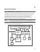
1 - General Information LAN Powerbus Dig I/O for fire/smoke detector Dig I/O for fixture open/close Control PC H Fixture Dig I/O for buttons and indicators MCCD Ready Test Tray of cells Start Power + Sense lines Bar Code Scanner Serial communications Figure 1-7. Typical Cell Forming Station ♦ ♦ ♦ ♦ ♦ ♦ ♦ ♦ ♦ The control PC sends a signal via the LAN to the digital I/O to turn on the Ready light on the test fixture. This tells the operator that the system is ready for another tray of cells.
2 Installation Inspection When you receive your equipment, inspect it for any obvious damage that may have occurred during shipment. If there is damage, notify the shipping carrier and the nearest Agilent Sales and Support Office immediately. The list of Agilent Technologies Sales and Support Offices is at the back of this guide. Warranty information is printed in the front of this guide.
2 - Installation Table 2-2. Accessories (continued) Item Manufacturer’s Part Number Description Documentation Package Agilent E4373A Contains user documentation, software drivers, and utility programs . Serial cable Agilent 34398A RS-232 null-modem cable for port A or B. (see figure 2-4 for schematic) 37-pin D-sub connector AMP 205210-2 Mating connector for front panel channel connectors. Eight connectors are required for each 64-channel card.
Installation - 2 Location Agilent E4370A MCCD Mainframe The outline diagrams in Appendix C give the dimensions of your Agilent MCCD mainframe. The mainframe may be installed free-standing, but must be located with sufficient space at the sides and back of the unit for adequate air circulation. You can rack mount the mainframe in standard 600 mm (23.8 in.) width system cabinets. This provides sufficient clearance for airflow. Support rails are also required when rack mounting the mainframe.
2 - Installation Table 2-4.
Installation - 2 ♦ It is good engineering practice to either twist or shield the sense and power wires. ♦ Twist the power wires together and keep them as short as possible. ♦ Twist the sense wires together but do not twist them together with the power wires. ♦ If possible, shield the sense wires. Connect the shield to the case. ♦ Keep the total cable length as short as possible. ♦ Use low resistance fixture contacts.
2 - Installation Power Bus Connections CAUTION: Observe polarity when making the power bus connections to both the Agilent MCCD mainframe and the Agilent Powerbus Load. Reversed polarity connections will result in damage to both the Agilent MCCD mainframe and the Agilent Powerbus load. The negative (− −) bus bar on the Agilent MCCD mainframe is connected to chassis ground.
Installation - 2 Table 2-6. Ampacity and Resistance of Stranded Copper Conductors AWG No. Area in mm2 5.26 8.36 13.3 21.1 33.6 53.5 67.4 85.0 107 10 8 6 4 2 1/0 2/0 3/0 4/0 Ampacity Resistance in Ω/meter 0.00327 0.00206 0.00129 0.00081 0.00051 0.00032 0.00025 0.00020 0.00016 40 60 80 105 140 195 225 260 300 Resistance in Ω/feet 0.00099 0.00062 0.00039 0.00025 0.000156 0.000098 0.000078 0.000062 0.000049 Notes 1. Wire ampacities are based on 30° C ambient temperature with conductor rated at 60° C. 2.
2 - Installation + Charging values based on: Power/channel = 18W Efficiency = 80% Power bus voltage = 24V - charging = 160A + Discharging values based on: Power/channel = 13.5W Efficiency = 75% Power bus voltage = 26.
Installation - 2 1. Multiply the power used by one cell times the number of cells in the Agilent MCCD. Divide the result by the efficiency of the unit to determine the total input power required for that mainframe. The efficiency of the unit in charging mode is assumed to be 80%, which is a worst-case value as far as calculating the total power required by the mainframe. #_of_cells × power_per_cell = Max_power_in 0.8 2.
2 - Installation Digital Connections Each Agilent E4370A MCCD mainframe has a 16-bit digital I/O port. Digital I/O configuration can be done with the Agilent MCCD Configuration Screens as described in chapter 3 or with the Agilent MCCD User Interface as described in chapter 4. All pins do not have to be configured the same. Some can be used as isolated outputs while others are single ended I/O. The functions can also be mixed, some pins can be general purpose I/O while others have a specific purpose.
Installation - 2 External Trigger This external trigger input is used to start the cell forming sequence. Power Fail Depending on how the system is configured, when true, this input signal will cause the Agilent MCCD to perform a shutdown, at which time it saves its state for a later restart. A power fail output signal is also available to indicate when the shutdown state has been saved.
2 - Installation The following figure illustrates some typical DIO hardware connections. + 16.5 V maximum connect to pins 0 through 7 Coil current 0.25A maximum 7 6 5 4 3 2 1 0 7 6 5 4 3 2 1 0 TTL, AS, CMOS, HC . . . . . . . . . . Connect common to connect to pins 2, 4, 6, 8 7 6 5 4 3 2 1 0 connect to pins 1, 3, 5, 7 connect to pins 0 through 7 7 6 5 4 3 2 1 0 Connect common to A) Relay Driver Example Circuit B) Digital Interface Example Circuit Figure 2-4.
Installation - 2 1 2 3 4 5 Pin 1 2 3 4 5 6 7 8 9 6 7 8 9 DB-9 male connector Input/Output Input Output Common Output Input Description no connection Receive Data (RxD) Transmit Data (TxD) not used Signal ground not used Request to Send (RTS) Clear to Send (CTS) no connection Figure 2-5. RS-232 A and B Connectors The following diagram describes the cable connections between the Agilent MCCD RS-232 ports and any local peripherals such as a PC or barcode scanner.
2 - Installation Installing the API Library and Measurement Log Utility Software for the Agilent MCCD consists of the API library and a measurement utility. This software is provided with the Agilent E4373A Documentation package. You need to install this software to use the supplied C-language function calls to control the Agilent MCCD as part of a automated manufacturing process. A setup program is provided on the disk to install the client API files and measurement utility on your PC.
3 Configuration Configuring the LAN The connection to the LAN is through a standard 8-pin 10Base-T connector on the rear panel, which must first be configured according to the directions in this section. Configuring the unit for LAN communications consist of three steps: 1. Configure the HyperTerminal program on your PC to communicate with the Agilent E4370A MCCD. The HyperTerminal program is provided on Windows 95 and Windows NT.
3 - Configuration In the COM Properties box: select the following port settings: Bits per second 9600 Data bits 8 Parity None Stop Bits 1 Flow control None Then click OK. In the File menu Select the Properties command In the Properties box: Select the Settings tab. Under Emulation, make sure that Auto detect is selected.
Configuration - 3 MCCD Configuration Screens 1) Network Configuration 2) Identification Configurations 3) Digital I/O Configuration 4) Perform Calibration 5) Miscellaneous Configuration Type a number and press Enter For now, you will only be accessing the Network Configuration and the Identification Configuration screens. Network Configuration NOTE: The settings that you enter in this screen are determined by your network administrator.
3 - Configuration The Agilent MCCD is shipped from the factory without a password being set. A network Password can be assigned to the Agilent E4370A MCCD to prevent unauthorized users from controlling the unit over the network. This is the same password that must be used when programming the Agilent MCCD using the API functions. Identification Configuration In the Initial Screen, select 2 to configure the identification of your Agilent MCCD. The information in this screen is for identification only.
Configuration - 3 Miscellaneous Configuration In the Initial Screen, select 5 to configure the language used in the Agilent MCCD User Interface. You can choose between English and Japanese. This screen also lets you program the auxiliary bias output on the back of the Agilent MCCD mainframe. The bias voltage can be programmed from 5 volts to 24 volts in 0.1 volt increments.
3 - Configuration Digital I/O Configuration Digital I/O Configuration over the LAN is ENABLED 1) To ENABLE Digital I/O Configuration over the LAN 2) To DISABLE Digital I/O Configuration over the LAN 3) To configure Digital I/O Type a number and press Enter or ctrl-G to return to initial screen To continue configuring the Digital I/O, press 3. The pin numbers of the Digital I/O connector appear on the screen. Refer to Figure 2-2 for the physical locations of the pins.
Configuration - 3 Pin 0 Digital I/O Configuration 1) 2) 3) 4) 5) 6) 7) 8) 9) 10) 11) 12) 13) 14) Change Change Change Change Change Change Change Change Change Change Change Change Change Change to to to to to to to to to to to to to to External Fault Input External Fault Output External Interlock General Purpose I/O General Purpose Input General Purpose Output External Trigger External Fault Output General Purpose Output Power Fail Input Power Fail Output Power Fail Output Output and not Fault In Out
3 - Configuration Mixed Configuration Example The following example illustrates a mixed digital I/O configuration. In this example, ♦ Pins 0, 2, 4, and 6 are configured for External Fault Output Isolated High True (selection 11). ♦ Pins 1, 3, 5 and 7 the corresponding second pins of each isolated pair. ♦ Pins 8 through 10 are configured as General purpose I/O, high true (selection 7), referenced to the common connector.
4 Agilent MCCD User Interface Description The Agilent MCCD User Interface lets you interactively monitor and control the Agilent MCCD System. This interface is accessed using a standard web browser on a PC located anywhere on the LAN. No special software other than the web browser needs to be installed on the PC to use this interface. PC Requirements The PC must have one of the following web browsers installed: ♦ Netscape Navigator 3.03 or greater ♦ Microsoft Internet Explorer 3.
4 - User Interface Localization The user interface pages are provided in English and Japanese. You can specify the default language during installation of the Agilent MCCD. (You can also change the language from the System page once the Agilent MCCD User Interface is running.) Access The user interface is accessed by starting a web browser on a LAN-connected PC and specifying the following URL: http://
/ where is the IP address or name of the particular Agilent MCCD unit being monitored.User Interface - 4 Using the Agilent MCCD Measurement Log Utility If you are using the Agilent MCCD User Interface to create and run a cell forming sequence, you may want to transfer the data from the data log memory to your PC for analysis and storage at the completion of the cell forming sequence. Use the Agilent MCCD Measurement Utility to transfer the data from the data log memory to a file on your client PC.
4 - User Interface Raw log Transfers all of the logged data in the order that it was logged. Sorted by cell Transfers all of the logged data sorted by cell. Data is organized from first cell to last cell. Individual files per cell Transfers all of the logged data and creates a separate data file for each cell. 4. When you select Raw log or Sorted by cell, you must enter a filename in which to store the data. Select the Browse button to chose a directory in which to put the file.
5 Programming Overview A Cell Forming Overview The cell forming process of the Agilent E4370A MCCD consists of a series of steps or actions that are performed on a group of cells until the process is complete. This cell forming process is here referred to as a sequence, the essence of which consists of three steps: charging the cell, resting the cell, and discharging the cell. These steps may be repeated a number of times and in any order within the sequence, depending on your process.
5 - Programming Overview Start STEP Continue in step Test outcome? FALSE TRUE Test action? FAIL Remove cell from sequence NEXT Go to NEXT step Figure 5-1. Test Outcome Flowchart Cell Forming Example The following table documents a sequence consisting of four steps. Figure 5-2 illustrates how three of the cells behave as the sequence is running. Each step in the sequence is performed on all cells simultaneously. Sequence steps and actions are as follows.
Programming Overview - 5 Step 1 In Step 1, all cells are set to charge at a constant current of 0.295 amperes until the voltage reaches 4.2 volts. It continues charging at the 4.2 volt limit, however the charging current now starts decreasing from its 0.295 ampere limit setting. The cell continues charging until the cell current falls to 0.02 amperes. When this occurs, the cell goes to the next step, the resting state. This is shown occurring for cell 1 and cell 2 in Figure 5-2.
5 - Programming Overview STEP 4 END (volts) STEP 3 END STEP 1 END STEP 2 END VOLTAGE (4) (amps) ND E COTAG SE OL EST E V T RU T T EN R R T U S C TE UE TR CELL 1 CURRENT (3) (2) (+ 0.5) (1) (0) (- 0.5) (0) (5) (10) (15) Charge (20) Rest (35) Rest STEP 4 END STEP 3 END STEP 2 END (volts) (30) Discharge STEP 1 END VOLTAGE (25) TIME (40) (minutes) CURRENT (amps) (4) (3) (2) VO SE C T LTA ON TR ES GE D U T E T EN R R T U S C TE UE TR CELL 2 (1) (+ 0.5) (0) (0) (- 0.
Programming Overview - 5 Function Call Overview The driver function calls that control the cell forming process of the Agilent E4370A MCCD are classified into the following broad categories: Cell Grouping functions - configure groups of cells for independent sequence control. Step/Test functions - set up and control individual steps in a cell forming sequence. Sequence Control functions - control the run states of the instrument Protection functions - set up the protection states of the instrument.
5 - Programming Overview Grouping Functions The group handle returned by cfOpenGroup can be used with any of the functions in the list below. These functions control or query a specific group. If a function is not in this list, it cannot be used with a group handle obtained from cfOpenGroup.
Programming Overview - 5 To program one test to cause a cell to fail if the voltage does not exceed 4 volts within 30 minutes, and another test to cause a test to fail if the voltage reaches 4 volts in under 5 minutes use: cfSetSeqTest(server, 1, CF_VOLT_LE, 4, CF_TEST_AT, 30 * SECONDS_PER_MINUTE, CF_FAIL); cfSetSeqTest(server, 1, CF_VOLT_GE, 4, CF_TEST_BEFORE, 5 * SECONDS_PER_MINUTE, CF_FAIL); The time test type and time limit determines when a measurement is performed.
5 - Programming Overview After selftest is completed and there is dc voltage on the power bus, the instrument moves to the CF_IDLE state. In this state the instrument is waiting and ready to start a cell forming sequence. The instrument returns to the CF_IDLE state when a cell-forming sequence completes. Note that an Abort function also places the instrument in the CF_IDLE state. A cell forming sequence can only be defined or recalled from non-volatile memory when the Agilent MCCD is in the CF_IDLE state.
Programming Overview - 5 Instrument Protection The following diagram shows the various protection states of the instrument. cfProtect() cfShutdown() CF_POWER_FAIL_IN CF_EXT_FAULT_IN CF_HIGH_RAIL_STAT CF_LOW_RAIL_STAT CF_OVERTEMPERATURE Failed selftest Internal hardware failure CF_PROTECTED CF_HW_FAILED Cycle ac power CF_EXT_INTERLOCK CF_INTERLOCKED cfProtectClear() PREVIOUS STATE CF_NOT_READY CF_EXT_INTERLOCK PREVIOUS STATE Figure 5-4.
5 - Programming Overview Power Fail Operation The Agilent E4370A MCCD can operate in one of two power-fail shutdown modes. The mode is set by the cfSetShutdownMode() command. When the mode is set to CF_AUTO, a true signal on the CF_POWER_FAIL_IN digital input will cause the Agilent MCCD to perform a shutdown, at which time it saves its state in nonvolatile memory. When the mode is set to CF_MANUAL, an automatic shutdown is not performed (API commands such as cfShutdown must be used to do it manually).
Programming Overview - 5 The power-on and cfReset instrument settings are: Output State = OFF Output Voltage = 0 volts Output Current = 0 amperes Groups = None Defined Sequence Step = None Defined Sequence Test = None Defined Measurement Interval = All steps ∆V = Infinity ∆I = Infinity ∆t = Infinity Trigger Source = LAN Digital Port = 0 Probe Test Resistance = Infinity Sense Probe Test = Off Shutdown Mode = MANUAL Shutdown Delay = 60 seconds Server Timeout = 60 seconds Note that power-on and cfReset() clea
5 - Programming Overview Measurement Log The Agilent E4370A MCCD logs measurement data at the beginning, end, and can be programmed to log measurement data throughout each sequence step. Voltage and current for each output are continuously monitored and whenever either changes by a user-specified threshold or a when a specified time period has elapsed, a log entry is made for that output.
Programming Overview - 5 NOTE: The measurement log contents are cleared when a sequence is initiated.
5 - Programming Overview The output voltage is regulated and measured at the power output terminals unless the remote sense function is used. The Agilent MCCD can be configured to regulate and measure the voltage at either the power terminals or the sense terminals. To set and query where the voltage is sensed, use: cfSetSense(); cfGetSense(); Direct output control CAUTION Direct output control should not be used for charging cells.
Programming Overview - 5 Selftest The Agilent E4370A MCCD has a built in selftest capability, which is performed at power-on. This limited selftest verifies proper operation of the memory functions, serial communications functions, analog-to-digital converter functions, and the voltage programming of each output regulator. The selftest also checks for the presence of an external dc source on the power bus.
5 - Programming Overview Since calibration can take up to 15 minutes for an Agilent MCCD with 256 channels, calibration functions do not wait for calibration to complete. They return immediately after starting calibration. During calibration, the CF_CALIBRATING_STAT bit is true in the status word returned by cfGetInstStatus(). When calibration is finished, the CF_CALIBRATING_STAT bit goes false, and a calibration error is indicated by the status bit CF_CAL_ERROR_STAT.
Programming Overview - 5 Probe check Probe check includes three separate functions: a continuity check, a power probe resistance check, and a sense probe resistance check. All probe check functions require a cell to be connected to the channel outputs. The continuity check is a low-current stimulus test that should be performed prior to the power probe test, or the sense probe test. Its primary function is to identify misaligned or bad probes.
6 Language Dictionary API Usage Guidelines This Application Programming Interface lets you create an application program on a PC to control the operation of one or more Agilent MCCD units over a LAN. The API consists of a dynamic link library (DLL) that provides a set of driver functions that are called by the application program to access Agilent MCCD features. This section gives the syntax and parameters for all the API cell forming (cf) functions used by the Agilent MCCD.
6 - Language Dictionary Password Protection An application program must provide a password to open a connection to a server. As shipped from the factory, the Agilent MCCD is not password protected. You may set an Agilent MCCD server password during the installation procedure using the Agilent MCCD Configuration Screens.
Language Dictionary - 6 cfMeasDCResistance cfMeasOutputProbeResistance cfMeasProbeContinuity cfMeasSenseProbeResistance cfMeasVoltage cfOpen cfOpenGroup cfProtect cfProtectClear cfReadMeasLog cfReadTestLog cfReadSerial cfReset cfResetSeq cfRestart cfSaveOutputConfig cfSelftest cfSetAutoConnect cfSetCurrent cfSetDigitalConfig cdSetDigitalPort cfSetErrorFunction cfSetGroup cfSetMeasLogInterval cfSetOutputConfig cfSetOutputProbeTest cfSetOutputState cfSetSense cfSetSenseProbeTest cfSetSeqStep cfSetSeqTest cfSe
6 - Language Dictionary API Function Definitions cfAbort Syntax int cfAbort(CF_HANDLE server); Description Aborts a forming sequence, which sets the run state to CF_IDLE. In the idle state the output conditions of each cell are defined by the functions cfSetVoltage, cfSetCurrent, and cfSetOutputState. The server argument can be either a handle to a group obtained by cfOpenGroup, or a handle to all cells in the instrument if no groups are defined.
Language Dictionary - 6 cfCalTransfer CAUTION: Make sure that no cells are connected when executing cfCalTransfer. Syntax int cfCalTransfer(CF_HANDLE server); Description Begins a transfer calibration sequence. This function uses the instrument's internal references to calibrate the measurement and output circuits of each channel. There should not be any loads or cells connected to the outputs when this command is given.
6 - Language Dictionary cfGetCellStatus Syntax int cfGetCellStatus(CF_HANDLE server, int cell, CF_CELL_STATUS *status); Description Returns a value in the variable pointed to by status which indicates the current status of a cell in the forming process. The possible return values are: CF_UNTESTED CF_PASSED CF_SEQUENCE_FAILED CF_OUT_PROBE_FAILED CF_SENSE_PROBE_FAILED CF_INACTIVE CF_SEQUENCING CF_ABORTED The cell has not started a sequence since ac power was last turned on.
Language Dictionary - 6 cfGetDigitalConfig Syntax int cfGetDigitalConfig(CF_HANDLE server, int bitnum, CF_EXT_SIGNAL *signal, CF_POLARITY *polarity, CF_REFERENCE *reference); Description This function returns the function and logic sense mapping any of the 16 pins of the digital I/O port. See the function cfSetDigitalConfig for a detailed description of digital I/O port configuration.
6 - Language Dictionary Example void query_groups(CF_SERVER server) { char names[CF_MAX_GROUPS][CF_MAX_GROUP_NAME_LEN]; int starts[CF_MAX_GROUPS]; int sizes[CF_MAX_GROUPS]; cfGetGroups(server, names, starts, sizes); } cfGetInstIdentify Syntax int cfGetInstIdentify(CF_HANDLE server, char *idstring); Description This command returns a description of the instrument.
Language Dictionary - 6 cfGetMeasLogInterval Syntax int cfGetMeasLogInterval(CF_HANDLE server, int step_number, float *volt_interval, float *curr_interval, float *time_interval); Description Returns voltage, current, and time change criteria that are used to determine when data is logged. The server argument can be either a handle to a group obtained by cfOpenGroup, or a handle to all cells in the instrument if no groups are defined.
6 - Language Dictionary cfGetOutputState Syntax int cfGetOutputState(CF_HANDLE server, CF_OUTPUT_STATE *state); Description Returns the output state of the Agilent MCCD when the run state is CF_IDLE. The server argument can be either a handle to a group obtained by cfOpenGroup, or a handle to all cells in the instrument if no groups are defined. The possible return values are: CF_OUTPUT_OFF CF_OUTPUT_CHARGE CF_OUTPUT_DISCHARGE The output state of the Agilent MCCD is off.
Language Dictionary - 6 cfGetSenseProbeTest Syntax int cfGetSenseProbeTest(CF_HANDLE server, CF_BOOLEAN *on_off); Description Returns the setting of the sense probe test. The setting is either ON or OFF. The server argument can be either a handle to a group obtained by cfOpenGroup, or a handle to all cells in the instrument if no groups are defined.
6 - Language Dictionary cfGetSeqTestAnd Syntax int cfGetSeqTestAnd(CF_HANDLE server, CF_READP *read_pos, int *step_number, CF_SEQ_TEST *meas_test_type, float *limit, CF_TIME_TEST *time_test_type, float *time, CF_SEQ_ACTION *action, int *count); Description Returns the parameters of the sequence tests defined by the functions cfSetSeqTest or cfSetSeqTestAnd. The server argument can be either a handle to a group obtained by cfOpenGroup, or a handle to all cells in the instrument if no groups are defined.
Language Dictionary - 6 cfGetShutdownDelay Syntax int cfGetShutdownDelay(CF_HANDLE server, float *delay); Description Returns the delay value that is set by cfSetShutdownDelay(). cfGetShutdownMode Syntax int cfGetShutdownMode(CF_HANDLE server, int *mode); Description Returns the shutdown mode, CF_AUTO or CF_MANUAL.
6 - Language Dictionary cfGetVoltage Syntax int cfGetVoltage(CF_HANDLE server, float *voltage); Description Returns the idle state voltage setting set by cfSetVoltage. The idle state voltage is the value that the cell voltage will be set to when the forming sequence is in the idle state and the output state is enabled. The server argument can be either a handle to a group obtained by cfOpenGroup, or a handle to all cells in the instrument if no groups are defined.
Language Dictionary - 6 cfMeasCapacityWS Syntax int cfMeasCapacityWS(CF_HANDLE server, int cell, float *reading); Description Returns the accumulated capacity in watt-seconds of a cell in its present step. The capacity is reset to zero at the start of each step. If the cell is not in the forming state, the special value CF_NOT_A_NUMBER is returned. The cell argument can be an individual cell number from 1 to 256, or the constant CF_ALL_CELLS to request readings for all cells.
6 - Language Dictionary To make an effective probe resistance measurement, there should be some significant current through the probe contacts to the cells. The cfSetVoltage, cfSetCurrent, and cfSetOutputState commands can be used to set up the proper conditions for this measurement.
Language Dictionary - 6 cfMeasVoltage Syntax int cfMeasVoltage(CF_HANDLE server, int cell, float *reading); Description Returns the measured cell voltage in volts for a particular cell or for all cells. Voltage is measured at the selected sense terminals for each cell. The cell argument can be an individual cell number from 1 to 256, or the constant CF_ALL_CELLS to request readings for all cells.
6 - Language Dictionary Example #define MY_GROUP "1.5Ahour" /* * Define group named "1.5Ahour" containing 64 cells * starting at cell 129. * Define a sequence step for the group, then free the group handle. */ void group_example(CF_HANDLE server) { CF_HANDLE group_handle; cfSetGroup(server, MY_GROUP, 129, 64); cfOpenGroup(server, MY_GROUP, &group_handle); cfSetSeqStep(group_handle, 1, CF_CHARGE, 5.0, 1.0, 100.0, 0.
Language Dictionary - 6 The measurement log contains measurements acquired during the forming sequence. For the sequence step types CF_CHARGE, CF_DISCHARGE, or CF_REST, a log entry is made at the beginning and end of a step. Additional log entries are made whenever the voltage, current, or time meet the criteria specified by the function cfSetMeasLogInterval. For all other sequence step types, only one entry is made containing a specific measurement.
6 - Language Dictionary For sequence steps of type CF_CHARGE, CF_DISCHARGE, or CF_REST, the format is: cell-number step-number time status entry-type volt-reading curr-reading amp-hours watt-hours .
Language Dictionary - 6 cfReadTestLog Syntax int cfReadTestLog(CF_HANDLE server, CF_READP *read_pos, int bufsize, char *buffer, int *retcount); Description Returns up to bufsize characters from the test log. The test log contains entries which describe any errors that occur during calibration or selftest. The number of characters read into the buffer is returned in retcount. The value pointed to by the read_pos argument controls which portion of the log is read.
6 - Language Dictionary cfRestart Syntax int cfRestart(CF_HANDLE server); Description This command causes the Agilent MCCD to recall a previously saved restart state. The Agilent MCCD must be in the CF_IDLE state to perform a restart. The existence of a restart state can be queried by testing the CF_RESTART bit of the status returned from cfGetInstStatus.
Language Dictionary - 6 cfSetAutoConnect Syntax int cfSetAutoConnect(CF_HANDLE server, CF_BOOLEAN on_off); Description This command turns the automatic reconnect feature of the mccd.dll file located on the client computer on or off. The Agilent MCCD mainframe server will close a connection if there is no activity for a period longer than the time set by cfSetServerTimeout. If the automatic reconnect feature is set to CF_ON, the client mccd.
6 - Language Dictionary cfSetDigitalConfig Syntax int cfSetDigitalConfig(CF_HANDLE server, int bitnum, CF_EXT_SIGNAL signal, CF_POLARITY polarity, CF_REFERENCE reference); Description NOTE: The Agilent MCCD Configuration screens (see chapter 3) control the availability of cfSetDigitalConfig. If this menu item is set to lock out programmable access, cfSetDigitalConfig will return the error CF_ACCESS_DENIED Sets the operation of any of the 16 pins of the digital I/O port.
Language Dictionary - 6 When an output signal is programmed, the pin is driven by an open collector transistor. Writing a word to the port using cfSetDigitalPort will turn the transistor on or off based on the word and the polarity of the bit. Reading the port using cfGetDigitalPort returns the last value written to the bit. When an input signal is programmed, the state of the input can be read using cfGetDigitalPort. Writing to the port has no affect on the bit.
6 - Language Dictionary cfSetDigitalPort Syntax int cfSetDigitalPort(CF_HANDLE server, int data); Description Write data to the digital I/O port. Data must be sent as the equivalent of a 16-bit binary word. For example, sending a value of 0 sets all bits low. Sending a value of 65,535 sets all bits high.
Language Dictionary - 6 cfSetGroup Syntax int cfSetGroup(CF_HANDLE server, char *name, int start, int size); Description Defines a group of cells by specifying a starting cell number and the total number of cells in the group. Name is a null terminated character string that serves to identify the group. Once the group has been created, a handle can be obtained using cfOpenGroup for subsequent control with API functions. The number of characters in name must be less than CF_MAX_GROUP_NAME_LEN.
6 - Language Dictionary cfSetOutputProbeTest NOTE: The Agilent MCCD must be configured for remote voltage sensing to perform output probe testing. No output probe tests are performed if local voltage sensing is configured. Syntax int cfSetOutputProbeTest(CF_HANDLE server, float resistance); Description Sets the resistance limit which is used when the output probes are tested during a forming sequence.
Language Dictionary - 6 cfSetSense Syntax int cfSetSense(CF_HANDLE server, CF_SENSE sense); Description Sets voltage sense to remote or local sense. The sense argument is either CF_SENSE_REMOTE or CF_SENSE_LOCAL. The sense setting is stored in non-volatile memory and is retained when the ac power is off. See Also cfGetSense cfSetSenseProbeTest NOTE: The Agilent MCCD must be configured for remote voltage sensing to perform output probe testing.
6 - Language Dictionary CF_CHARGE CF_DISCHARGE CF_REST CF_ACR CF_DCR CF_TAG_ACR CF_TAG_DCR CF_TAG_OCV CF_TAG_CUM_AH CF_TAG_CUM_WH CF_RESET_CUM_AH CF_RESET_CUM_WH Constant voltage/constant current charge Constant voltage/constant current discharge Rest (output in high impedance state) AC resistance measurement DC resistance measurement Makes an ac resistance measurement which is identified in the measure log as a TaggedACR entry type.
Language Dictionary - 6 cfSetSeqTest Syntax int cfSetSeqTest(CF_HANDLE server, int step_number, CF_SEQ_TEST meas_test_type, float limit, CF_TIME_TEST time_test_type, float time, CF_SEQ_ACTION action); Description Define tests performed during sequence steps. These tests allow a cell to advance to the next step when a measured value is achieved, or to fail a cell and remove it from further stimulus if a failure limit is exceeded.
6 - Language Dictionary CF_NEG_DIDT_LE CF_DVMAX_GE CF_DVMAX_LE CF_DVMIN_GE CF_DVMIN_LE CF_DIMAX_GE CF_DIMAX_LE CF_DIMIN_GE CF_DIMIN_LE The change in the magnitude of current during the standard measurement interval that is negative, and the magnitude of the change is less than or equal to the programmed limit. The magnitude of the difference between the voltage and the maximum voltage observed during the step that is greater than or equal to the programmed limit.
Language Dictionary - 6 cfSetSeqTestAnd Syntax int cfSetSeqTestAnd(CF_HANDLE server, int step_number, CF_SEQ_TEST *meas_test_type, float *limit, CF_TIME_TEST time_test_type, float time, CF_SEQ_ACTION action, int count); Description This command is similar to cfSetSeqTest, but it allows multiple tests that are combined with a logical AND during a sequence. The action is not taken unless all measurement tests are true.
6 - Language Dictionary cfSetShutdownDelay Syntax int cfSetShutdownDelay(CF_HANDLE server, float delay); Description Sets the delay between the assertion of a true signal at a CF_POWER_FAIL_IN input and the start of an Agilent MCCD shutdown when the shutdown mode has been set to CF_AUTO. If the shutdown mode has been set to CF_MANUAL, the delay has no effect. The power-on setting for cfSetShutdownDelay is 60 seconds.
Language Dictionary - 6 cfSetVoltage CAUTION Direct output control should not be used for charging cells. There is no protection against overcharging when using direct output control. Use this mode only for diagnostic and debugging purposes. Syntax int cfSetVoltage(CF_HANDLE server, float voltage); Description Sets the output voltage for diagnostic or debugging purposes.
6 - Language Dictionary cfStateList Syntax int cfStateList(CF_HANDLE server, char *buffer); Description Returns a comma-separated and null terminated list of instrument state names that are stored on the server. The buffer must be large enough to hold a list of the names of the maximum number of states that can be saved in a Cell Forming Server. The constant CF_MAX_STATE_LIST_LEN can be used to allocate space for the buffer.
Language Dictionary - 6 cfWriteSerial Syntax int cfWriteSerial(CF_HANDLE server, CF_SERIAL_PORT port, char *port_data, int count); Description Writes count data words to the serial port.
7 C Program Examples Example 1 This following C program shows you how to implement the example discussed in the beginning of chapter 5 using the API cell forming (cf) functions. The cell forming functions are included with the driver software supplied with the Agilent E4373A documentation package. #include #include #define SECONDS_PER_MINUTE 60.
7 - C Program Examples } while(presentState != CF_INITIATED); /* Start the sequence */ cfTrigger(server); /* Wait for the sequence to end */ do { cfGetRunState(server, &presentState); /* sleep or do something else */ } while(presentState == CF_FORMING); /* Read entire measurement log and write it to a disk file */ fp = fopen("logfile", "w"); for (read_pos = CF_READ_FIRST; ; ) { cfReadMeasLog(server, &read_pos, CF_ALL_CELLS, CF_ALL_STEPS, CF_MEAS_LOG_BUFSIZE, buf, &retcount); if (retcount) fputs(buf, fp); el
C Program Examples - 7 Example 2 This following C program shows you how to implement the example discussed at the end of chapter 1 using the API cell forming functions. Note that this example only includes a brief cell forming sequence and does not include error checking after each function call. It primarily describes how you can incorporate the various high-level features of the Agilent MCCD such as the digital I/O and the serial ports in a cell forming sequence.
7 - C Program Examples /*********************************************************************** Main function ***********************************************************************/ void main(int argc, char *argv[]) { char *szServerAddr = DEFAULT_SERVER; char *szPassword = DEFAULT_PASSWORD; CF_HANDLE hServer; int nResult; int nDigitalPort; char szBarCodeMsg[MAX_BARCODE]; int nBarCodeCount; int nRunState; CF_READP readPos; FILE *hFile; char szMeasBuffer[MEAS_BUF_SIZE]; int nMeasBufCount; float fCellResistan
C Program Examples - 7 /* Configure resistance limit for output probe test. */ cfSetOutputProbeTest(hServer, 0.1f); /* Mark outputs 65 - 256 as unused by this fixture. */ cfSetOutputConfig(hServer, 1, 14, CF_SET_ACTIVE); cfSetOutputConfig(hServer, 15, 256, CF_SET_INACTIVE); /* * Turn on the fixture ready light to tell the operator that the * system is ready for a new tray of cells.
7 - C Program Examples { cfGetDigitalPort(hServer, &nDigitalPort); if (nDigitalPort & DIG_START_BUTTON) break; /* Sleep for 1 second. */ Sleep(1000); } /* * Turn off the READY light and turn on the TEST light * to indicate to the operator that cell forming has started. */ cfGetDigitalPort(hServer, &nDigitalPort); nDigitalPort &= ~DIG_READY_LIGHT; nDigitalPort |= DIG_TEST_LIGHT; cfSetDigitalPort(hServer, nDigitalPort); /* Initiate the sequence.
C Program Examples - 7 /* Measure the internal resistance of all cells. */ cfMeasACResistance(hServer, CF_ALL_CELLS, fCellResistance); /* * Turn off the TEST light and turn on the READY light * to indicate that it the tray can be removed from the fixture. */ cfGetDigitalPort(hServer, &nDigitalPort); nDigitalPort &= ~DIG_TEST_LIGHT; nDigitalPort |= DIG_READY_LIGHT; cfSetDigitalPort(hServer, nDigitalPort); printf("Forming sequence complete.\n"); /* Close the server connection.
7 - C Program Examples Example 3 You can control up to 16 Agilent MCCDs from one PC and still achieve good system responsiveness, depending on the application program structure. This following C program example uses a multi-threaded program in which each thread can independently control one Agilent MCCD but can share data with a user interface thread. This provides the advantage of a central system view of all of the Agilent MCCDs, with the simplicity of each thread controlling only one Agilent MCCD.
C Program Examples - 7 // Signal threads to start reading logs. SetEvent(ThreadInfo[0].hStart); SetEvent(ThreadInfo[1].hStart); // Wait for threads to terminate. WaitForSingleObject(hReadThread0, INFINITE); WaitForSingleObject(hReadThread1, INFINITE); printf("Press any key to exit\n"); getchar(); } /***************************************************************************** Thread to read log from MCCD.
7 - C Program Examples /***************************************************************************** Return a timestamp string. *****************************************************************************/ void GetTimeStamp(char *szTimeStamp) { char buf[128]; _strdate(szTimeStamp); strcat(szTimeStamp, " "); _strtime(buf); strcat(szTimeStamp, buf); strcat(szTimeStamp, "\r\n"); } /***************************************************************************** Error handler function.
A Specifications Hardware Specifications Specifications in Table A-1 are warranted. Specifications apply over an ambient temperature range of 0° C to 40° C. When charging, specifications apply for charging voltages from 0.5 V to maximum, and charge currents from minimum to maximum. When discharging, specifications apply for discharging voltages from 1.5 V to maximum and discharging currents from minimum to maximum.
A - Specifications Tables A-2 through A-4 list the supplemental characteristics of the Agilent MCCD System. Requirements for the external power bus source are also listed. Characteristics are not warranted but are descriptions of typical performance determined either by design or by type testing. Table A-2. Agilent E4370A/E4374A/E4375A MCCD Characteristics Parameter Condition Value E4374A E4375A Ah Capacity Measurement Accuracy % of reading + offset ≤ 2 A: > 2 A: ± (0.1% +1mAh/h) N/A ± (0.10% +1.
Specifications - A Table A-2. Agilent E4370A/E4374A/E4375A MCCD Characteristics (continued) Parameter Auxiliary bias output voltage accuracy Auxiliary bias output noise Non-isolated Digital I/O Characteristics Condition max. low-level output voltage min. high-level output voltage Isolated Digital I/O Characteristics Maximum Airflow Maximum Exhaust Air Temperature Rise Dimensions Weight Value % of setting at any voltage and current peak to peak at any voltage and current max.
B Calibration Calibration Types There are three types of calibration available for the Agilent MCCD System. ♦ Full calibration, which calibrates the Agilent E4370A MCCD mainframe and all installed Agilent E4374A/E4375A Charger/Discharger cards. ♦ Transfer calibration, which calibrates only the Agilent E4374A/E4375A Charger/Discharger cards that are installed in the mainframe. ♦ Mainframe reference calibration, which calibrates only the Agilent E4370A MCCD mainframe.
A - Specifications Transfer Calibration NOTE: Transfer calibration does not require an external voltmeter. It can be performed independently of the full calibration or the mainframe reference calibration. However, transfer calibration requires a 24 V, 4 A dc source to be connected to the power bus. During transfer calibration, each individual channel is sequentially connected to the internal reference and gain and offset corrections are calculated and stored in non-volatile memory.
Specifications - A RS-232 PORT A NORMAL / CAL CAL PORT 4 3 2 1 On Off o o o o o o GPIB-232CV-A o +24 V RAIL SUPPLY (4 A min. Current) GPIB Address = 22 CONFIG = Cr MODE = C Baudrate = 9600 Data Format = Odd, Checking disabled, 1 stop bit, 8 bits/char Handshake = XON/XOFF disabled Sense 3458A Multimeter MENU Input NUMERIC/USER HI LO FUNCTION/RANGE Power On Off I Figure B-1.
A - Specifications Accessing Calibration Calibration control is accessible by one of three methods: ♦ the Agilent MCCD Configuration Screens, ♦ API calls over the LAN, ♦ the Web-based Agilent MCCD User Interface. This section describes the first method in detail. Note: Transfer calibration can also be run by pressing the Cal button on the rear panel. Agilent MCCD Configuration Screens You can calibrate the Agilent MCCD using the Agilent MCCD Configuration Screens on your PC.
Specifications - A Rear panel transfer calibration switch This push button switch is accessible through a recessed hole on the rear panel. When pressed, it initiates a transfer calibration sequence inside the Agilent MCCD. This is useful if you have replaced an Agilent E4374A/E4375A Charger/Discharger card inside the mainframe. Note that the transfer calibration recalibrates all of the cards inside the mainframe. Indicator lights next to the transfer calibration switch indicate the calibration status.
C Dimension Drawings Figure C-1 shows a simplified outline diagram of the Agilent E4370A MCCD mainframe. Figure C-2 shows a simplified outline diagram of the Agilent E4371A Powerbus Load. The dimension drawings included in the back of this documentation binder provide additional information. EXHAUST AIR EXHAUST AIR TOP VIEW 68.0mm 35.7mm AIR FLOW 540.5mm AIR FLOW EXHAUST AIR 425.
C - Dimension Drawings HOT EXHAUST AIR 68.0mm TOP VIEW 28.0mm 540.5mm AIR FLOW SIDE VIEW 425.5 mm FRONT VIEW E4371A POWERBUS LOAD 221.5mm LINE On Off Figure C-2.
D Sense and Power Connector Pinouts The figures and tables in this appendix document the sense and power pinout assignments on the front of the Agilent E4370A MCCD mainframe (refer to Figure 1-2).
D - Sense and Power Connector Pinouts SENSE POWER 1 2 3 4 5 6 19 + + + + + + 7 + 8 1 2 3 4 5 6 + + + + + + + 7 + 1 + 37 SENSE + + + + SENSE + + + + + + + + + + + + + + + + + + + + 19 + + + + + + + + 41 42 43 44 45 46 47 48 + + + + + + + 1 + 37 20 1 + POWER 41 42 43 44 45 46 47 48 1 + 37 + 20 SENSE 9 10 11 12 13 14 15 16 + + 5 33 34 35 36 37 38 39 40 37 POWER + POWER 33 34 35 36 37 38 39 40 19 + 20 9 10 11
Sense and Power Connector Pinouts - D SENSE POWER 129 130 131 132 133 134 135 136 19 + + + + + + + + + + + + + + + 1 + 37 SENSE + + + + SENSE + + + + + + + + + + + + + + + + + + + + 19 + + + + + + + + 169 170 171 172 173 174 175 176 + + + + + + + 1 + 37 20 1 + POWER 169 170 171 172 173 174 175 176 1 + 37 + 20 SENSE 137 138 139 140 141 142 143 144 + + 5 161 162 163 164 165 166 167 168 37 POWER + POWER 161 162 163 164 165 16
D - Sense and Power Connector Pinouts Table D-1.
Sense and Power Connector Pinouts - D Table D-2.
D - Sense and Power Connector Pinouts Table D-3.
Sense and Power Connector Pinouts - D Table D-4.
E In Case of Trouble Introduction The Agilent E4370A MCCD System has a built-in self test capability which is performed at power-on. Additionally a more complete self test can be done by executing the cfSelftest; function or running self test from the Agilent MCCD User Interface. This selftest capability provides an effective diagnostic tools to isolate problems for rapid repair. Refer to chapter 5 under Selftest for more information.
E - In Case of Trouble Agilent E4374A/E4375A Fault 1, 2, 3, 4 Indicates an internal hardware fault such as Selftest failure. Calibration error. Hardware error. To read the text-based error message, use the cfReadSelftestLog() API function. If you are using the Agilent MCCD User Interface, you can read the error messages by accessing the System page, selecting Calibration and Selftest, and then clicking on Selftest Log. Write down the error message and contact your Agilent Service Engineer.
Index —A— abort, 70 airflow mainframe, 25 powerbus load, 25 amp-hour capacity measurement, 17 API, 21 API functions guidelines, 67 summary, 68 API library installation, 36 application programming interface, 21 autoconnect, 89 auxiliary output connections, 35 ratings, 35 —B— basic functions, 10 block diagram, 9 blocking functions, 67 —C— C program expanded example, 107 multi-threaded example, 112 sequence example, 105 cables, 24 calibration, 44, 70 calibration switch, 123 configuration screen, 122 connecti
Index cfSetOutputProbeTest, 94 cfSetOutputState, 94 cfSetSense, 95 cfSetSenseProbeTest, 95 cfSetSeqStep, 95 cfSetSeqTest, 97 cfSetSeqTestMult, 99 cfSetSerialConfig, 99 cfSetServerTimeout, 99 cfSetShutdownDelay, 100 cfSetShutdownMode, 100 cfSetTimeout, 100 cfSetTrigSource, 100 cfSetVoltage, 101 cfShutdown, 101 cfStateDelete, 101 cfStateList, 102 cfStateRecall, 102 cfStateSave, 102 cfTrigger, 102 cfWriteSerial, 103 channel inactive, 26 channel connections, 25 characteristics, 115 external source, 117 powerbus
Index sequence step time, 78 sequence test parameters, 77, 78 serial port configuration, 78 serial port status, 78 step number, 79 trigger source, 79 user identification, 79 voltage, 80 grouping functions, 54 memory requirements, 60 —H— high rail, 57 HW failed, 57 HyperTerminal configuration, 37 —N— next, 49 non-volatile memory, 56 not ready, 56, 57 null modem cable, 34 —O— open group, 83 open connection, 83 Out of Memory, 53, 60 output configuration, 56 output sensing, 62 output state, 62 overtemperatur
Index serial port data, 86 test log data, 87 rear panel mainframe, 12 remote sensing, 27 repacking, 23 reset, 58, 87 reset sequence, 87 resistance measurement, 61 restart, 88 RS-232 connections, 34 interface, 34 run states, 55 —S— safety summary, 3 safety symbols, 4 save output configuration, 88 saving output configuration, 56 selftest, 63, 88, 135 error messages, 136 semi-automated example, 22 sense connector pinouts, 127 wiring, 27 sequence control, 55 serial port configuration, 64 status, 64 server time
Agilent Sales and Support Office For more information about Agilent Technologies test and measurement products, applications, services, and for a current sales office listing, visit our web site: http://www.agilent.com/find/tmdir You can also contact one of the following centers and ask for a test and measurement sales representative. United States: Agilent Technologies Test and Measurement Call Center P.O.