Service Guide Publication number 01680-97016 October 2005 For Safety information, Warranties, and Regulatory information, see the pages at the end of the book. © Copyright Agilent Technologies 2001, 2004-2005 All Rights Reserved.
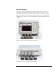
The Agilent 1680/90-Series Logic Analyzer–At a Glance Features Some of the main features of the Agilent 1680A,AD-Series Logic Analyzers are as follows: • Standalone benchtop logic analyzer • Microsoft Windows® XP Professional operating system • 132 data channels and 4 clock/data channels on the Agilent 1680A,AD • 98 data channels and 4 clock/data channels on the Agilent 1681A,AD • 64 data channels and 4 clock/data channels on the Agilent 1682A,AD • 32 data channels and 2 clock/data channels on t
Service Strategy The service strategy for this instrument is the replacement of defective assemblies. This service guide contains information for finding a defective assembly by testing and servicing the Agilent 1680/90-series logic analyzers. This logic analyzer can be returned to Agilent for all service work, including troubleshooting. Contact your nearest Agilent Technologies Sales Office for details.
In This Book This book is the service guide for the Agilent 1680/90-Series Logic Analyzers and is divided into eight chapters. Chapter 1 contains information about the logic analyzer and includes accessories, specifications and characteristics, and equipment required for servicing. Chapter 2 tells how to prepare the logic analyzer for use. Chapter 3 gives instructions on how to test the performance of the logic analyzer. Chapter 4 contains calibration instructions for the logic analyzer.
Contents The Agilent 1680/90-Series Logic Analyzer–At a Glance Features 2 Service Strategy 3 In This Book 1 General Information Accessories 10 Specifications 11 Characteristics 11 Recommended Test Equipment 14 2 Preparing for Use Power Requirements 16 Operating Environment 16 Storage 16 To inspect the logic analyzer 16 To apply power 17 To connect the 1690A,AD-series logic analyzer to a host PC To start the user interface 18 To clean the logic analyzer 18 To test the logic analyzer 18 17 3 Testing Pe
Contents To test the threshold accuracy 28 Set up the equipment 28 Connect and configure the logic analyzer Test the ECL Threshold 30 Test the 0 V User Threshold 31 Test the next pod 32 29 To set up the logic analyzer for the state mode tests To test the single-clock, single-edge, state acquisition Set up the equipment 37 Connect and configure the logic analyzer 37 Verify the test signal 40 Check the setup/hold combination 41 Test the next channels (1680/81A,AD and 1690/91A,AD) To test the multiple-cloc
Contents 5 Troubleshooting To install the fan guard 78 To use the flowcharts 79 Troubleshooting the Agilent 1680A,AD-series 80 To check the power-up tests 87 To test the power supply voltages 87 To test the LCD display signals 89 To test disk drive voltages 90 To verify the CD-ROM 92 To recover the operating system 93 Troubleshooting the Agilent 1690A,AD-series To verify connectivity 99 To test the power supply voltages 95 100 General Troubleshooting 103 To run the self-tests 103 Acquisition board s
Contents 1690A,AD-series disassembly/assembly 133 Prepare the instrument for disassembly 133 To remove the chassis from the sleeve 133 To remove the fascia 134 To remove the acquisition board 136 To remove the deck 137 To remove the power supply 137 To remove the distribution board 138 To remove the fans 139 To remove the line filter 140 To remove the front panel and front frame 141 7 Replaceable Parts Replaceable Parts Ordering 144 Replaceable Parts List 145 Exploded View 146 Agilent 1680A,AD-Series Repl
1 General Information This chapter lists the accessories, the specifications and characteristics, and the recommended test equipment.
Chapter 1: General Information Accessories The following accessory is supplied with the Agilent 1680/90-series logic analyzers. The part number is current as of the print date of this edition of the Service Guide, but further upgrades may change the part number. Do not be concerned if the accessory you receive has a different part number.
Chapter 1: General Information Specifications The specifications are the performance standards against which the product is tested. Maximum State Speed (selectable) Minimum Master to Master Clock Time* Threshold Accuracy 200 MHz 5.000 ns ± (65 mV + 1.5% of threshold setting) Setup/Hold Time* Single Clock, Single Edge 4.5/-2.0 ns through -2.0/4.5 ns, adjustable in 100 ps increments Single Clock, Multiple Edges 5.0/-2.0 ns through -1.5/4.
Chapter 1: General Information Probes Maximum Input Voltage + 40V Peak AC+DC, CAT 1 Auxiliary Power Power Through Cables 1/3 amp at 5 V maximum per cable, CAT 1 Operating Environment (for indoor use only) Temperature: • Instrument: 0° C to 55° C (+32° F to 131° F). • Probe lead sets and cables: 0° C to 65° C (+32° F to 149° F). • Disk media: 10° C to 40° C (+50° F to 104° F). Humidity: Instrument, probe lead sets, and cables, up to 80% relative humidity at +40° C (+122° F).
Chapter 1: General Information Dimensions 1680A,AD-Series 1690A,AD-Series 13
Chapter 1: General Information Recommended Test Equipment Equipment Required Equipment Critical Specifications Recommended Model/Part Use* Pulse Generator 200 MHz, 2.5 ns pulse width, <600 ps rise time 8133A Option 003 P,T Digitizing Oscilloscope ≥6 GHz bandwidth, <58 ps rise time 54750A mainframe with 54751A P plug-in module Function Generator Accuracy (5)(10-6) frequency, DC offset voltage ±1.6 V 33250A P Digital Multimeter 0.1 mV resolution, 0.
2 Preparing for Use This chapter gives you instructions for preparing the logic analyzer for use.
Chapter 2: Preparing for Use Power Requirements The logic analyzer requires a power source of either 115 Vac or 230 Vac, –22 % to +10 %, single phase, 48 to 66 Hz, CAT II pollution degree 2, 140/400 Watts nominal maximum power (1680A/AD-series), and 76/200 Watts nominal maximum power (1690A/AD-series). Operating Environment The operating environment is listed in chapter 1. The logic analyzer will operate at all specifications within the temperature and humidity range given in chapter 1.
Chapter 2: Preparing for Use 3 Inspect the product for physical damage. Check the logic analyzer and the supplied accessories for obvious physical or mechanical defects. If you find any defects, contact your nearest Agilent Technologies Sales Office. Arrangements for repair or replacement are made, at Agilent Technologies' option, without waiting for a claim settlement. To apply power These steps are required for all 1680A,AD and 1690A,AD-series logic analyzers.
Chapter 2: Preparing for Use To start the user interface Start the Agilent Logic Analyzer application from the Start menu or using a shortcut. On the desktop, the Agilent Logic Analyzer icon looks like: Refer to the Agilent Logic Analyzer on-line help for information on how to operate the user interface. Also, refer to the window icon reference on the inside front cover of this service manual for a brief explanation of the Agilent Logic Analyzer standard icons.
3 Testing Performance This chapter tells you how to test the performance of the logic analyzer against the specifications listed in chapter 1.
Chapter 3: Testing Performance The Logic Analyzer Interface To select a field on the logic analyzer screen, use the arrow keys to highlight the field, then press the Select key. Provided on the inside front cover of this manual is a list of logic analyzer icons that can be referenced while performing test procedures. For more information about the logic analyzer interface, refer to the Agilent Logic Analyzer application’s online help.
Chapter 3: Testing Performance To make the test connectors To make the test connectors The test connectors connect the logic analyzer to the test equipment. Materials Required Description Recommended Part Qty BNC (f) Connector 1250-0698 5 100 Ω 1% resistor 0698-7212 8 Berg Strip, 17-by-2 1 Berg Strip, 6-by-2 4 20:1 Probe 54006A 2 Jumper wire 1 Build four test connectors using BNC connectors and 6-by-2 sections of Berg strip: a Solder a jumper wire to all pins on one side of the Berg strip.
Chapter 3: Testing Performance To make the test connectors f On two of the test connectors, solder a 20:1 probe. The probe ground goes to the same row of pins on the test connector as the BNC ground tab. 2 Build one test connector using a BNC connector and a 17-by-2 section of Berg strip: a Solder a jumper wire to all pins on one side of the Berg strip. b Solder a jumper wire to all pins on the other side of the Berg strip.
Chapter 3: Testing Performance To set up the test equipment and the logic analyzer To set up the test equipment and the logic analyzer Before testing the specifications of the Agilent 1680A,AD-series or 1690A,ADseries logic analyzer, the test equipment and the logic analyzer must be set up and configured. These instructions include detailed steps for initially setting up the required test equipment and the logic analyzer.
Chapter 3: Testing Performance To set up the test equipment and the logic analyzer b Configure the oscilloscope according to the following table. Oscilloscope Setup Acquisition Display Trigger [Shift] ∆ Time Averaging: On # of averages: 16 Graticule graphs: 2 Level: 0.0 V Stop src: channel 2 [Enter] Channel 1 Channel 2 Define meas External Scale Attenuation: 20.00:1 Scale: 200 mV/div Offset: - 1.300 V External Scale Attenuation: 20.00:1 Scale: 200 mV/div Offset: - 1.
Chapter 3: Testing Performance To set up the test equipment and the logic analyzer Set up the 1690A,AD-series logic analyzer Power-up self tests are done on the logic analyzer system components when power is applied. Logic analyzer peripheral communication tests are done when the host PC recognizes the hosted logic analyzer hardware. Any problems reported should be cleared before going further. For more information, refer to Chapter 5 and Chapter 8. 1 Connect the logic analyzer to the host PC.
Chapter 3: Testing Performance To set up the test equipment and the logic analyzer 2 In the Analysis System Self Tests dialog, select the self test options: • Include interactive tests — causes interactive tests to appear in the selection lists. • Run repetitively — runs the selected tests repetitively until you click Stop. • Stop on fail — if you are running multiple tests or running tests repetitively, this causes the tests to stop if there is a failure.
Chapter 3: Testing Performance To set up the test equipment and the logic analyzer To stop running test, click Stop. To reset the self-test options, click Reset. To view the log file, click Logs..., select the log file you want to view, and click Open. If, after completing the self tests, you have failures or you have questions about the performance of the logic analysis system, contact Agilent Technologies sales or support at http://www.agilent.com/find/contactus.
Chapter 3: Testing Performance To test the threshold accuracy To test the threshold accuracy Testing the threshold accuracy verifies the performance of the following specification: • Clock and data channel threshold accuracy. These instructions include detailed steps for testing the threshold settings of pod 1. After testing pod 1, connect and test the rest of the pods one at a time. To test the next pod, follow the detailed steps for pod 1, substituting the next pod for pod 1 in the instructions.
Chapter 3: Testing Performance To test the threshold accuracy Connect and configure the logic analyzer 1 Using the 17-by-2 test connector, BNC cable, and probe tip assembly, connect the data and clock channels of Pod 1 to the free side of the BNC Tee. 2 Configure the logic analyzer: a Click the Bus/Signal Setup icon. The Analyzer Setup dialog opens. b In the Buses/Signals tab, click Delete All at the bottom of the dialog. c Using the mouse, activate all Pod 1 channels.
Chapter 3: Testing Performance To test the threshold accuracy Test the ECL Threshold 1 Set up the logic analyzer: a In the Analyzer Setup dialog, click the threshold field for Pod 1. The Threshold Settings dialog appears. b In the Threshold Settings dialog, select Standard and ECL (–1.30 V). c Click OK to close the Threshold Settings dialog. d Click OK to close the Analyzer Setup dialog. 2 Test the high-to-low transition: a On the DC source, enter a voltage setting of –1.384 V.
Chapter 3: Testing Performance To test the threshold accuracy Test the 0 V User Threshold 1 Set up the logic analyzer: a On the logic analyzer, click the Setup dialog opens. Bus/Signal Setup icon. The Analyzer b In the Analyzer Setup dialog, click the threshold field for Pod 1. The Threshold Settings dialog appears. c In the Threshold Settings dialog, select User Defined and enter 0 V in the associated field. d Click OK to close the Threshold Settings dialog.
Chapter 3: Testing Performance To test the threshold accuracy Test the next pod 1 Using the 17-by-2 test connector and probe tip assembly, connect the data and clock channels of the next pod to the output of the function generator until all pods have been tested. 2 Start with “Connect and configure the logic analyzer” on page 29 substituting the next pod to be tested for pod 1.
Chapter 3: Testing Performance To set up the logic analyzer for the state mode tests To set up the logic analyzer for the state mode tests 1 Set up the logic analyzer: a If you have not already done so, do the procedure “To set up the test equipment and the logic analyzer” on page 23. b Exit and restart the Agilent Logic Analyzer application to reinitialize the logic analyzer. 2 Configure the Analyzer Setup dialog: a Click the Sampling Setup icon. b Select State - Synchronous Sampling.
Chapter 3: Testing Performance To set up the logic analyzer for the state mode tests 3 Configure the trigger according to your logic analyzer: a In the Listing window, click on the trigger pattern field for My Bus 1 to select. b Enter the following pattern for your logic analyzer. 1680A,AD, 1690A,AD - "AA" 1681A,AD, 1691A,AD - "2A" 1682A,AD, 1692A,AD - "AA" 1683A,AD, 1693A,AD - "A" c Click the Trigger Setup icon. d For the Default Storage, select Store Nothing.
Chapter 3: Testing Performance To set up the logic analyzer for the state mode tests select the M1 marker. c In the Position box, select Value. d Click on the Occurs... button and the Value dialog appears. e Click on the Find occurrences field, and enter 4096.
Chapter 3: Testing Performance To set up the logic analyzer for the state mode tests h Repeat steps b through f to configure marker M2 using the following pattern according to the logic analyzer being tested. 1680A,AD, 1690A,AD - "55" 1681A,AD, 1691A,AD - "15" 1682A,AD, 1692A,AD - "55" 1683A,AD, 1693A,AD - "5" i Click OK to close the Value dialog. j In the Listing Viewer Properties dialog, select Beginning Of Data in the “from” field. The logic analyzer markers are now configured to verify the test data.
Chapter 3: Testing Performance To test the single-clock, single-edge, state acquisition To test the single-clock, single-edge, state acquisition Testing the single-clock, single-edge, state acquisition verifies the performance of the following specifications: • Minimum master-to-master clock time. • Maximum state acquisition speed. • Setup/Hold time for single-clock, single-edge, state acquisition.
Chapter 3: Testing Performance To test the single-clock, single-edge, state acquisition 2 Using SMA cables, connect the oscilloscope to the pulse generator channel 1 Output, channel 2 Output, and Trigger Output.
Chapter 3: Testing Performance To test the single-clock, single-edge, state acquisition Connect the 1682/83/92/93A,AD Logic Analyzer to the Pulse Generator Testing Combination Connect to 8133A Channel 2 Output Connect to 8133A Channel 2 Output Connect to 8133A Channel 1 Output 1 Pod 1, channel 3 Pod 2, channel 3 Pod 3, channel 3 Pod 4, channel 3 Pod 1, channel 11 Pod 2, channel 11 Pod 3, channel 11* Pod 4, channel 11* Pod 1 clock/data channel (Clk 1) *1682A,AD or 1692A,AD only.
Chapter 3: Testing Performance To test the single-clock, single-edge, state acquisition Verify the test signal 1 Check the clock period. Using the oscilloscope, verify that the master-tomaster clock time is 5.000 ns, +0 ps or −100 ps: a In the oscilloscope Timebase menu, select Scale: 1.000 ns/div. b In the oscilloscope Timebase menu, select Position. Using the oscilloscope knob, position the clock waveform so that a rising edge appears at the left of the display.
Chapter 3: Testing Performance To test the single-clock, single-edge, state acquisition c If the pulse width is outside the limits, adjust the pulse generator channel 2 width until the pulse width is within limits. Check the setup/hold combination The following setup/hold combinations will be tested: Setup/Hold Combinations Test Combination Setup/Hold Times Setup/Hold Window Sample Position (in middle of Window) 1 4.50/-2.0 ns 2.5 ns -3.25 ns 2 -2.0/4.50 ns 2.5 ns +3.
Chapter 3: Testing Performance To test the single-clock, single-edge, state acquisition c On the oscilloscope, select [Shift] ∆ Time, then select [Enter] to display the setup time (∆ Time(1)-(2)). d Adjust the pulse generator channel 1 Delay until the pulses are aligned according to the setup time of the setup/hold combination selected, +0.0 ps or –100 ps. 3 Select the logic analyzer sample positions: a Click the Sampling Setup icon. The Analyzer Setup dialog opens with the Sampling tab displayed.
Chapter 3: Testing Performance To test the single-clock, single-edge, state acquisition d Click OK to close the Sample Positions dialog. 4 Select the clock to be tested: The following clock configurations will be used in steps 4, 5, and 6. a In the Analyzer Setup dialog, click on the Sampling tab. b In the Sampling tab, click the Master button for the first clock to be tested (Clk 1) and select Rising Edge.
Chapter 3: Testing Performance To test the single-clock, single-edge, state acquisition c Click the Master buttons for the remaining clocks and select Don't Care to turn off the other clocks. d Connect the clock to be tested to the pulse generator channel 1 output. e Click OK to close the Analyzer Setup dialog. 5 Verify the test data: a Click the Run icon. b If you have not already done so, do “Set up the Markers:” on page 34.
Chapter 3: Testing Performance To test the single-clock, single-edge, state acquisition then select [Enter] to display the setup time (∆ Time(1)-(2)). c Adjust the pulse generator channel 1 Delay until the pulses are aligned according to the setup time of the setup/hold combination selected, +0.0 ps or –100 ps. 9 Select the clock to be tested: The following clock configurations will be used in steps 9, 10 and 11. a In the Analyzer Setup dialog, click the Sampling tab.
Chapter 3: Testing Performance To test the single-clock, single-edge, state acquisition c Click the Master buttons for the remaining clocks and select Don't Care to turn off the other clocks. d Connect the clock to be tested to the pulse generator channel 1 output. e Click OK to close the Analyzer Setup dialog. 10 Verify the test data: a Click the Run icon. b If you have not already done so, do “Set up the Markers:” on page 34.
Chapter 3: Testing Performance To test the single-clock, single-edge, state acquisition Test the next channels (1680/81A,AD and 1690/91A,AD) Connect the next combination of data channels and clock channels; then, test them. Start with “Connect and configure the logic analyzer” on page 37, connect the next combination; then, continue through the complete test.
Chapter 3: Testing Performance To test the multiple-clock state acquisition To test the multiple-clock state acquisition Testing the multiple-clock, state acquisition verifies the performance of the following specifications: • Minimum master-to-master clock time. • Maximum state acquisition speed. • Setup/Hold time for multiple-clock, state acquisition. This test checks two combinations of data using multiple clocks at two selected setup/hold times.
Chapter 3: Testing Performance To test the multiple-clock state acquisition Connect and configure the logic analyzer 1 Using the 6-by-2 test connectors, connect the first combination of logic analyzer clock and data channels listed in one of the following tables to the pulse generator. If you are testing a 1680/81/90/91A,AD, you will repeat this test for the second combination. 2 Using SMA cables, connect channel 1, channel 2, and trigger of the oscilloscope to the pulse generator.
Chapter 3: Testing Performance To test the multiple-clock state acquisition Connect the 1682/83/92/93A,AD Logic Analyzer to the Pulse Generator Testing Combination Connect to 8133A Channel 2 Output Connect to 8133A Channel 2 Output Connect to 8133A Channel 1 Output 1 Pod 1, channel 3 Pod 2, channel 3 Pod 3, channel 3 Pod 4, channel 3 Pod 1, channel 11 Pod 2, channel 11 Pod 3, channel 11 * Pod 4, channel 11 * Clock/data channel for Pod 1, 2, 3, and 4 (Clk 1, Clk 2, Clk 3, Clk 4) *1682A, AD or 1692A,
Chapter 3: Testing Performance To test the multiple-clock state acquisition Verify the test signal 1 Check the clock period. Using the oscilloscope, verify that the master-tomaster clock time is 5.000 ns, +0 ps or –100 ps: a In the oscilloscope Timebase menu, select Scale: 1.000 ns/div. b In the oscilloscope Timebase menu, select Position. Using the oscilloscope knob, position the clock waveform so that a rising edge appears at the left of the display.
Chapter 3: Testing Performance To test the multiple-clock state acquisition b On the oscilloscope, select [Shift] + width: channel 1, then select [Enter] to display the data signal pulse width (+ width (1)). c If the pulse width is outside the limits, adjust the pulse generator channel 2 width until the pulse width is within limits. Check the setup/hold with single clock edges, multiple clocks The following setup/hold combinations will be tested.
Chapter 3: Testing Performance To test the multiple-clock state acquisition b In the oscilloscope timebase menu, select Position. Using the oscilloscope knob, position the data waveform so the falling edge is near the center of the display. c On the oscilloscope, select [Shift] ∆ Time, then select [Enter] to display the setup time (∆ Time(1)-(2)). d Adjust the pulse generator channel 1 Delay until the pulses are aligned according to the setup time of the setup/hold combination selected, +0.0 ps or –100 ps.
Chapter 3: Testing Performance To test the multiple-clock state acquisition d Connect all clock channels to the pulse generator channel 1 output. e Click OK to close the Analyzer Setup dialog. 4 Select the logic analyzer sample positions: a Click the Sampling Setup icon. The Analyzer Setup dialog opens with the Sampling tab displayed. b Click Sample Positions....
Chapter 3: Testing Performance To test the multiple-clock state acquisition 6 Enable the pulse generator channel 1 COMP (with the LED on). 7 Using the Delay mode of the pulse generator channel 1, position the pulses according to the setup/hold combination selected, +0.0 ps or –100 ps: a On the Oscilloscope, select [Define meas] Define ∆ Time - Stop edge: falling. b On the oscilloscope, select [Shift] ∆ Time. Select Start src: channel 1, then select [Enter] to display the setup time (∆ Time(1)-(2)).
Chapter 3: Testing Performance To test the multiple-clock state acquisition have been configured with Falling Edge. d Click OK to close the Analyzer Setup dialog. 9 Verify the test data: a Click the Run icon. b If you have not already done so, do “Set up the Markers:” on page 34. c If the "can't find 4096 occurence(s)" message does not appear, the test passes. The test passes when the logic analyzer finds all occurances of the patterns programmed into the Markers.
Chapter 3: Testing Performance To test the single-clock, multiple-edge, state acquisition To test the single-clock, multiple-edge, state acquisition Testing the single-clock, multiple-edge, state acquisition verifies the performance of the following specifications: • Minimum master-to-master clock time. • Maximum state acquisition speed. • Setup/Hold time for single-clock, multiple-edge, state acquisition.
Chapter 3: Testing Performance To test the single-clock, multiple-edge, state acquisition Connect and configure the logic analyzer 1 Using the 6-by-2 test connectors, connect the first combination of logic analyzer clock and data channels listed in one of the following tables to the pulse generator. If you are testing a 1680/81/90/91A,AD, you will repeat this test for the second combination. 2 Using the SMA cables, connect channel 1, channel 2, and trigger from the oscilloscope to the pulse generator.
Chapter 3: Testing Performance To test the single-clock, multiple-edge, state acquisition Connect the 1682/83/92/93A,AD Logic Analyzer to the Pulse Generator Testing Combination Connect to 8133A Channel 2 Output Connect to 8133A Channel Connect to 8133A 2 Output Channel 1 Output 1 Pod 1, channel 3 Pod 2, channel 3 Pod 3, channel 3 Pod 4, channel 3 Pod 1, channel 3 Pod 2, channel 3 Pod 3, channel 3 * Pod 4, channel 3 * Pod 1 clock/data channel (Clk1) *1682A,AD or 1692A,AD only.
Chapter 3: Testing Performance To test the single-clock, multiple-edge, state acquisition Verify the test signal 1 Check the clock period. Using the oscilloscope, verify that the master-tomaster clock time is 5.000 ns, +0 ps or –100 ps: a Enable the pulse generator channel 1, channel 2, and trigger outputs (LED off). b In the oscilloscope Timebase menu, select Scale: 2.000 ns/div. c In the oscilloscope Timebase menu, select Position.
Chapter 3: Testing Performance To test the single-clock, multiple-edge, state acquisition 2 Check the data pulse width. Using the oscilloscope, verify that the data pulse width is 3.000 ns, +0 ps or −100 ps: a In the oscilloscope Timebase menu, select Scale: 1.000 ns/div. b In the oscilloscope Timebase menu, select Position. Using the oscilloscope knob, position the data waveform so that the waveform is centered on the screen.
Chapter 3: Testing Performance To test the single-clock, multiple-edge, state acquisition 1 Using the Delay mode of the pulse generator channel 2, position the pulses according to the setup time of the setup/hold combination selected, +0.0 ps or –100 ps: a On the Oscilloscope, select [Define meas] Define ∆ Time - Stop edge: rising. b In the oscilloscope timebase menu, select Position. Using the oscilloscope knob, position the falling edge of the data waveform so that it is near the center of the display.
Chapter 3: Testing Performance To test the single-clock, multiple-edge, state acquisition d Click OK to close the Sample Positions dialog. 3 Select the clock to be tested: The following clock configurations will be used in steps 3, 4, and 5. a In the Analyzer Setup dialog, click the Sampling tab. b In the Sampling tab, click the Master button for the first clock to be tested (Clk 1) and select Both Edges.
Chapter 3: Testing Performance To test the single-clock, multiple-edge, state acquisition to turn off the other clocks. d Connect the clock to be tested to the pulse generator channel 1 output. e Click OK to close the Analyzer Setup dialog. 4 Verify the test data: a Click the Run icon. b If you have not already done so, do “Set up the Markers:” on page 34. c If the "can't find 4096 occurence(s)" does not appear, then the test passes.
Chapter 3: Testing Performance To test the single-clock, multiple-edge, state acquisition Test the next channels (1680/81A,AD and 1690/91A,AD) Connect the next combination of data channels and clock channels, then repeat the previous test. Start with “Connect and configure the logic analyzer” on page 58, connect the next combination, then continue through the complete test.
Chapter 3: Testing Performance To test the time interval accuracy To test the time interval accuracy Testing the time interval accuracy does not check a specification, but does check the following: • 125 MHz oscillator This test verifies that the 125 MHz timing acquisition synchronizing oscillator is operating within limits. Equipment Required Equipment Critical Specifications Recommended Model/Part Pulse Generator 200 MHz 2.
Chapter 3: Testing Performance To test the time interval accuracy 3 Set up the function generator according to the following table. Function Generator Setup Freq: 40.000 MHz Ampl: 1.00 Vpp Offset: 0.0 mV Modulation Off Connect and configure the logic analyzer 1 Using a 6-by-2 test connector, connect channel 0 of Pod 1 to the pulse generator channel 1 output. 2 Using the SMA cable and the BNC adapter, connect the External Input of the pulse generator to the Main Signal of the function generator.
Chapter 3: Testing Performance To test the time interval accuracy d Select an Acquisition Depth of 256K. 5 Configure the logic analyzer channels: a Click the Buses/Signals tab. In the Buses/Signals tab, click Delete All at the bottom of the dialog. b Using the mouse, select Pod 1 channel 0 to activate the channel. c Click the threshold field for Pod 1. In the Threshold Settings dialog, select Standard and ECL (–1.30). d Click OK to close the Threshold Settings dialog.
Chapter 3: Testing Performance To test the time interval accuracy b In the pop-up menu, select Rising Edge. Acquire and verify the test data 1 Click the Run icon to fill acquisition memory. 2 Set up the M1 marker for time interval measurement: a From the main menu, choose Markers>Properties.... b In the Marker Properties tab of the Waveform Properties dialog, select the M1 marker. c In the Position box, select Value. d Click Occurs.... e In the Value dialog, enter “1” in the Find occurrences field.
Chapter 3: Testing Performance To test the time interval accuracy f Click OK to close the Value dialog. 3 Set up the M2 marker for time interval measurement: a In the Marker Properties tab of the Waveform Properties dialog, select the M2 marker. b In the Position box, select Value. c Click Occurs.... d In the Value dialog, enter “16384” in the Find occurrences field. e Click OK to close the Value dialog. f In the Position box, select M1 in the “from” field.
Chapter 3: Testing Performance Performance Test Record Performance Test Record Agilent 1680/90-Series Logic Analyzer_______ Serial No.______________________ Work Order No.___________________ Recommended Test Interval - 2 Years/4000 hours Date___________________ Recommended next testing___________________ Temperature___________________ Test Settings Self-Tests Results Pass/Fail ________ Threshold Accuracy ± (65 mV + 1.
Chapter 3: Testing Performance Performance Test Record Performance Test Record (continued) Test Settings Results Pass/Fail Single-Clock, SingleEdge Acquisition All Pods, Channel 3 All Pods, Channel 11 Pass/Fail Setup/Hold Time 4.5/-2.0 ns Clk 1↑ Clk 2↑ Clk 3↑ Clk 4↑ ________ ________ ________ ________ Clk 1↓ Clk 2↓ Clk 3↓ Clk 4↓ ________ ________ ________ ________ Setup/Hold Time -2.0/4.
Chapter 3: Testing Performance Performance Test Record Performance Test Record (continued) Test Settings Results Disable pulse generator, channel 1 COMP (LED off) Single-Clock, Multiple-Edge Acquisition Pass/Fail All Pods, Channel 3 All Pods, Channel 11 Time Interval Accuracy Setup/Hold Time 5.0/-2.0 ns Clk 1 ↑ ↓ Clk 2 ↑ ↓ Clk 3 ↑ ↓ Clk 4 ↑ ↓ _______ _______ _______ _______ Setup/Hold Time -1.5/4.
Chapter 3: Testing Performance Performance Test Record 74
4 Calibrating and Adjusting This chapter gives you instructions for calibrating and adjusting the logic analyzer.
Chapter 4: Calibrating and Adjusting Logic analyzer calibration The logic analyzer circuitry of the Agilent 1680/90-series logic analyzers does not require an operational accuracy calibration. To test the logic analyzer circuitry against specifications (full calibration), refer to chapter 3, "Testing Performance.
5 Troubleshooting This chapter helps you troubleshoot the logic analyzer to find defective assemblies.
Chapter 5: Troubleshooting The troubleshooting consists of flowcharts, self-test instructions, and tests. This information is not intended for component-level repair. If you suspect a problem, start at the top of the first flowchart. During the troubleshooting instructions, the flowcharts will direct you to perform other tests. The service strategy for this instrument is the replacement of defective assemblies.
Chapter 5: Troubleshooting c Install the optional screws as shown. 3 After the required power-on troubleshooting and repair is complete, reverse the above procedure to remove the fan guard and reassemble the instrument. To use the flowcharts Flowcharts are the primary tool used to isolate defective assemblies. The flowcharts refer to other tests to help isolate the trouble. The circled letters on the charts indicate connections with the other flowcharts.
Chapter 5: Troubleshooting Troubleshooting the Agilent 1680A,AD-series Troubleshooting the Agilent 1680A,AD-series START Apply power. Observe the instrument front panel. Did the front panel indicators flash? No 2 No 3 Is the application Online? No 6B Yes Yes Does the display light up? 6A Yes Yes Are all instrument power supply fans running? Does the No application software launch? No 4 Do the self test. Refer to Chapter 5.
Chapter 5: Troubleshooting Troubleshooting the Agilent 1680A,AD-series 2 Are the power supply fans running? No Ensure the power cord is properly connected. Yes Are the instrument fans running? No Is the power cord connected? Yes Suspect the power supply. Perform "To test the power supply voltages" in Chapter 5. Yes Do all test points pass? No Reconnect the front panel cables. Reconnect the power cord. Yes Remove the cover. Ensure all front panel cables are properly connected.
Chapter 5: Troubleshooting Troubleshooting the Agilent 1680A,AD-series 3 Are the power supply fans running? No Yes Are both instrument fans stopped? Yes No Verify the fan voltage. Perform "To test the fan voltage" in Chapter 5. Are the fan voltages OK? No Suspect the power supply. Perform "To test the power supply voltages" in Chapter 5. Yes Do all test points pass? No Yes Replace the defective fan. Replace the distribution board. Replace the power supply.
Chapter 5: Troubleshooting Troubleshooting the Agilent 1680A,AD-series 4 Connect an external 800x600 PC monito to the instrument. Does the external monitor light up? No Yes Is the external monitor readable? No Possible problem with motherboard or PCI video board. Ensure PCI video board is seated in the motherboard connector. Yes Possible problem with LCD display, inverter, or cables. Is the PCI video No board seated in the motherboard? Reseat the PCI video board in the motherboard connector.
Chapter 5: Troubleshooting Troubleshooting the Agilent 1680A,AD-series 5 Does the blue Yes Agilent Logic Analyzer screen appear? No Does an *error message appear during POST? Does the instrument boot any further? No Replace the CPU motherboard. Yes Yes Remove power from instrument, remove cover, check that all cables are properly seated. Reapply power, observe if any error messages appear. No * Microsoft Windows XP Technical Resources will help identify the cause of specific error messages.
Chapter 5: Troubleshooting Troubleshooting the Agilent 1680A,AD-series 6A 6B Uninstall, then reinstall the Agilent Logic Analyzer application. Remove power from instrument, remove cover, check internal IEEE 1394 cabling. Does the application software launch? No Are all cables connected and seated? Yes Do error Yes messages appear? No Reconnect or reseat all internal cabling. Yes Perform "To recover the operating system" in Chapter 5. Reseat the PCI IEEE board in ISA slot 1*.
Chapter 5: Troubleshooting Troubleshooting the Agilent 1680A,AD-series 7 Possible problem with logic analyzer cables. Do the cable test in Chapter 5 on suspect pod. Does cable test pass? Yes The logic analyzer board if functioning properly. Yes Replace defective probe tip assembly. Yes Replace defective cable. No Swap suspect probe tip assembly with known good one. Does cable test pass? No Swap suspect cable assembly with known good one.
Chapter 5: Troubleshooting Troubleshooting the Agilent 1680A,AD-series To check the power-up tests The power-up self tests on the 1680A,AD-series logic analyzers is performed by the Microsoft Windows XP Professional operating system. As part of the Windows XP Professional power on self test (POST), the presence of all required system components is verified. 1 Close the Agilent Logic Analyzer application and all other applications running on the logic analyzer. 2 Shut down the instrument.
Chapter 5: Troubleshooting Troubleshooting the Agilent 1680A,AD-series 3 Remove the power supply from the instrument. Refer to “To remove the power supply” in Chapter 6. 4 After removing the power supply, connect a power cord to the power supply and plug the power cord into line power. 5 Using DVM, measure the power supply voltages. Power Supply Voltages CN1 CN2 Pin Voltage Pin Voltage 1-5 +3.3 V 1-4 -5.2 V 6-7 COM 5 +12 V 8-10 +5 V 6-8 -12 V 11-12 COM 9-12 COM 13-14 +3.
Chapter 5: Troubleshooting Troubleshooting the Agilent 1680A,AD-series To test the LCD display signals Before attempting to do this procedure, ensure that the video signal cable connected to the PCI video board is properly seated. Attempt to reseat the cable two or three times. If other repairs were done to the instrument, and the video is now no longer operating, it is very likely that the video cable is not properly seated.
Chapter 5: Troubleshooting Troubleshooting the Agilent 1680A,AD-series 4 Using an oscilloscope, probe pins 39 and 40 of J111 for +3.3Vdc If +3.3Vdc is present on J111 of pins 39 and 40, and digital signals are present on the video data pins indicated above, then the CPU board video circuit is operating properly. 5 Remove power. Allow time for the capacitors in the power supply to discharge before disconnecting the power supply, doing the repair, and reassembling the instrument.
Chapter 5: Troubleshooting Troubleshooting the Agilent 1680A,AD-series b As the instrument is booting, probe for digital signals on the hard disk drive connector according to the following table. Disk Drive Voltages Pin No. Signal Voltage Pin No. Signal Voltage Pin No.
Chapter 5: Troubleshooting Troubleshooting the Agilent 1680A,AD-series e While the instrument is attempting to save the file to flexible disk, probe for digital signals on the flexible disk drive connector according to the following table. Disk Drive Voltages Pin Signals Pin No.
Chapter 5: Troubleshooting Troubleshooting the Agilent 1680A,AD-series To recover the operating system To reinstall the operating system Reinstalling the operating system erases the entire hard disk drive and reinitializes the hard disk drive to its factory configuration. All user data stored on the hard disk drive will be lost. Reinstalling the operating system is necessary in case any system level files or other components of the operating system become corrupted.
Chapter 5: Troubleshooting Troubleshooting the Agilent 1680A,AD-series the application software. Problems with the Operating System Operating system applies to the Agilent 1680A,AD-series logic analyzers. The likely cause would be the operating system if the error or unusual behavior appeared while doing an operating system task, like printing or configuring the network.
Chapter 5: Troubleshooting Troubleshooting the Agilent 1690A,AD-series Troubleshooting the Agilent 1690A,AD-series START Apply power. Are all instrument and power supply fans running? No 2 Yes Launch the Agilent Logic Analyzer application software on the host PC. Does the No application software launch? 3A Yes Is the application Online? No 3B Yes Do the self test. Refer to Chapter 5. Do the self tests pass? Replace the acquisition board.
Chapter 5: Troubleshooting Troubleshooting the Agilent 1690A,AD-series 2 Are the power supply fans running? No Ensure the power cord is properly connected. Yes Is the power cord connected? No Reconnect the power cord. Yes Are the instrument fans running? No Suspect the power supply. Perform "To test the power supply voltages" in Chapter 5. Yes Do all test points pass? No Yes Ensure all instrument cables are connected and properly seated. Replace the power supply.
Chapter 5: Troubleshooting Troubleshooting the Agilent 1690A,AD-series 3B 3A Uninstall, then reinstall the Agilent Logic Analyzer application. Is the IEEE 1394 No cable connected and seated? Reconnect or reseat IEEE 1394 cable. Yes Does the application software launch? No Perform " To verify connectivity" in Chapter 5. Yes Do error Yes messages appear? Possible problem with host operating system. Consult host PC documentation.
Chapter 5: Troubleshooting Troubleshooting the Agilent 1690A,AD-series 4 Possible problem with logic analyzer cables. Do the cable test in Chapter 5 on suspect pod. Does cable test pass? Yes The logic analyzer board if functioning properly. Yes Replace defective probe tip assembly. Yes Replace defective cable. No Swap suspect probe tip assembly with known good one. Does cable test pass? No Swap suspect cable assembly with known good one.
Chapter 5: Troubleshooting Troubleshooting the Agilent 1690A,AD-series To verify connectivity Using Windows Device Manager and Task Manager, you can quickly determine if the Agilent Logic Analyzer application software is correctly installed on a host PC. Task Manager Use Task Manager to see if the agLogicSvc is running. The agLogicSvc is started when the PC is booted and establishes connection with the 1690A,AD-series hosted logic analyzer when the logic analyzer is connected to the PC.
Chapter 5: Troubleshooting Troubleshooting the Agilent 1690A,AD-series Device Manager Use Device Manager to see if the Agilent Logic Analyzer device has been properly installed. The Device Manager should include an entry "Logic Analyzers" with the device "Agilent Technologies 1680/1690 Series Analyzer". If the logic analyzer device is not listed, then uninstall and reinstall the Agilent Logic Analyzer application software.
Chapter 5: Troubleshooting Troubleshooting the Agilent 1690A,AD-series a Click on the Start button in the task bar, then select Shut Down. b In the Shut Down window, select Shut Down from the menu, then select the OK button. 3 Remove the power supply from the instrument. Refer to “To remove the power supply” in Chapter 6. 4 After removing the poser supply, connect a power cord to the power supply and plug the power cord into line power. 5 Using DVM, measure the power supply voltages.
Chapter 5: Troubleshooting Troubleshooting the Agilent 1690A,AD-series 6 Note problems with the power supply, then unplug the power supply from line power. Return to flow chart.
Chapter 5: Troubleshooting General Troubleshooting General Troubleshooting This section includes troubleshooting procedures that can be done on either the Agilent 1680A,AD- or 1690A,AD-series logic analyzers. Before any of these procedures can be done on an Agilent 1690A,AD-series logic analyzer, the logic analyzer must be connected to a host PC and both the host PC and the logic analyzer must be turned on.
Chapter 5: Troubleshooting General Troubleshooting 5 In the Analysis System Self Tests dialog, select the self test options: • Include interactive tests — causes interactive tests to appear in the selection lists. • Run repetitively — runs the selected tests repetitively until you click Stop. • Stop on fail — if you are running multiple tests or running tests repetitively, this causes the tests to stop if there is a failure. • Double-click item to start — lets you double-click a test to start it.
Chapter 5: Troubleshooting General Troubleshooting The self tests can be run one at a time by clicking on the self-test of interest. The results of the individual test will be reported under Results. For example, if you select the Serial Memory Test and the highest reporting level, the following results should be reported in the status window: To stop a running test, click Stop. To reset the self-test options, click Reset. To view the log file, click Logs...
Chapter 5: Troubleshooting General Troubleshooting Acquisition board status LEDs The acquisition board has four LEDs located close to its IEEE 1394 port. The LEDs report the status of configuration of both the interface field programmable gate array (FPGA) and the IEEE 1394 link layer on the acquisition board. Green LEDs The green LEDs display the status of loading of the IEEE 1394 link layer.
Chapter 5: Troubleshooting General Troubleshooting LED #1 (closest to the red LED) - the on-board processor is properly initialized and running, attempting to load the IEEE 1394 link layer configuration LED #2 - the IEEE 1394 link layer is loaded and configured LED #3 - the IEEE 1394 is loaded, properly configured, and is running A blinking green LED signifies a failure of one of the above steps. In this case, the acquisition board must be replaced.
Chapter 5: Troubleshooting General Troubleshooting 2 Set up the pulse generator according to the following table. Pulse Generator Setup Timebase Channel 2 Trigger Channel 1 Mode: Int Mode: Pulse Divide: Divide 1 Mode: Square Period: 20.000 ns Divide: Square ÷ 1 Ampl: 0.50 V Delay: 0.000 ns Offs: 0.00 V Ampl: 0.80 V Ampl: 0.80 V Offs: -1.30 V Offs: -1.
Chapter 5: Troubleshooting General Troubleshooting e Click the Master button for the clock to be tested; then, select Both Edges. 5 Configure the pod under test: a In the Analyzer Setup dialog, click the Buses/Signals tab b Click Delete All at the bottom of the window. c Using the mouse, activate all channels for the pod under test. Assign channels to bus/signal name My Bus 1. d Click on the threshold field for the pod under test. The Threshold Settings dialog appears.
Chapter 5: Troubleshooting General Troubleshooting similar to the figure below. 7 Repeat steps 3 through 7 to test other logic analyzer cables. 8 Disconnect the test equipment from the logic analyzer. 9 If the display looks like the figure, the cable passed the test. If the display does not look similar to the figure, there is a possible problem with the cable or probe tip assembly. Causes for cable test failures include the following: • Open channel. • Channel shortened to a neighboring channel.
Chapter 5: Troubleshooting General Troubleshooting analyzer Trigger In BNC. c Using a BNC-banana cable, connect the voltmeter to the logic analyzer Trigger Out BNC. The voltmeter will display a voltage approximately 3 Vdc. 4 Configure the external trigger: a Select the Trigger Setup icon. b In the Advanced Trigger dialog, for Trigger Sequence Step 1, select “Arm in from” instead of “Anything” as the event to trigger on. c Then, select “External trigger” as the source of the arming signal.
Chapter 5: Troubleshooting General Troubleshooting To test the auxiliary power The +5 V auxiliary power is protected by a current overload protection device. If the current on pins 1 and 39 exceed 0.33 amps, the circuit will open. When the short is removed, the circuit will reset in approximately 1 minute. There should be +5 V after the 1 minute reset time. Equipment Required Equipment Critical Specifications Digital Multimeter 0.1 mV resolution, better than 0.
6 Replacing Assemblies This chapter contains the instructions for removing and replacing the assemblies of the logic analyzer. Also in this chapter are instructions for returning assemblies.
Chapter 6: Replacing Assemblies 1680A,AD-series disassembly/assembly 1680A,AD-series disassembly/assembly Prepare the instrument for disassembly Do this procedure before doing any disassembly procedure on the instrument. 1 Close the Agilent Logic Analyzer application software. 2 Gracefully shut down the operating system and remove power when shutdown is complete. 3 Remove the power cord. 4 Move the instrument to a static safe work environment.
Chapter 6: Replacing Assemblies 1680A,AD-series disassembly/assembly 7 Reverse this procedure to install the chassis into the sleeve. When reassembling, check the following: all assemblies are properly installed before installing the chassis into the sleeve. ensure all exposed cables are dressed properly so the sleeve does not cause any damage to the cables. To remove the acquisition board 1 Do the procedure "To remove the chassis from the sleeve". 2 Turn the chassis upside down.
Chapter 6: Replacing Assemblies 1680A,AD-series disassembly/assembly 6 Slide the acquisition board out the rear panel of the logic analyzer. Steps to remove probe shroud from acquisition board. 7 Using a hex screwdriver, remove two hex nuts from the acquisition board trigger BNC connectors. 8 Using a Torx T-10 screwdriver, remove five screws that secure the probe shroud to the acquisition board. Reverse this procedure to install the acquisition board.
Chapter 6: Replacing Assemblies 1680A,AD-series disassembly/assembly To remove the power supply 1 Do the procedure "To remove the chassis from the sleeve". 2 Disconnect the 16-pin power supply cable and the power sense cable from the distribution board. 3 Using a Torx T-15 screwdriver, remove four screws that secure the power supply to the chassis. 4 Lift the power supply out of the chassis. 5 Disconnect the 14-pin and the 10-pin power supply cables from the distribution board.
Chapter 6: Replacing Assemblies 1680A,AD-series disassembly/assembly 6 Reverse this procedure to install the power supply When installing a replacement power supply, transfer the power supply cables and the grommet to the replacement power supply as shown: To remove the hard disk drive 1 Do the procedure "To remove the chassis from the sleeve". 2 Using a Torx T-15 screwdriver, remove four screws that secure the hard disk drive to the chassis. 3 Lift the hard disk drive out of the chassis.
Chapter 6: Replacing Assemblies 1680A,AD-series disassembly/assembly To remove the CD-ROM drive assembly 1 Do the procedure "To remove the chassis from the sleeve". 2 Disconnect the IEEE 1394 cable from the PCI IEEE 1394 interface board. Disengage the cable from the cable clamps on the top of the CD-ROM drive assembly. 3 Remove the data cable, power cable and audio cable from the CD-ROM drive interface board.
Chapter 6: Replacing Assemblies 1680A,AD-series disassembly/assembly 4 Using a Torx T-6 screwdriver, remove three screws that secure the CDROM drive to the bottom bracket. Lift the CD-ROM drive out of the bottom bracket. 5 Reverse this procedure to reassemble and install the CD-ROM drive. Ensure the motherboard is properly installed before installing the CDROM drive. To remove the flexible disk drive 1 Do the procedure "To remove the chassis from the sleeve".
Chapter 6: Replacing Assemblies 1680A,AD-series disassembly/assembly 3 Using a Torx T-8 screwdriver, remove two screws that secure the flexible disk drive to the chassis. 4 Slide the flexible disk drive out the rear of the front panel and out of the chassis. 5 Reverse this procedure to install the flexible disk drive. When installing a new flexible disk drive, industrial double-sided tape (Agilent 0460-2010 or similar) is required to dress the cable onto the flexible disk drive. Apply the tape as shown.
Chapter 6: Replacing Assemblies 1680A,AD-series disassembly/assembly To remove the PCI boards The following PCI boards are installed on the logic analyzer motherboard: PCI IEEE 1394 board (slot 2, closest to the CD-ROM drive) PCI display board (slot 3) slot covers (slot 3 and slot 4) 1 Do the procedure "To remove the chassis from the sleeve".
Chapter 6: Replacing Assemblies 1680A,AD-series disassembly/assembly To remove the motherboard 1 Do the procedure "To remove the chassis from the sleeve". 2 Do the procedure "To remove the CD-ROM drive" . 3 Remove both PCI peripheral boards from the motherboard using the procedure "To remove the PCI boards.
Chapter 6: Replacing Assemblies 1680A,AD-series disassembly/assembly 6 Using a Torx T-10 screwdriver, remove the 6 screws that secure the motherboard to the chassis. 7 Reverse this procedure to install the motherboard. If the motherboard requires replacing, then do the following steps: Transfer the I/O panel to the replacement board 1 Using a 3/16 inch hex nut driver, remove 6 hex studs that secure the I/O panel to the parallel port, VGA port and COM1 port. 2 Remove the I/O panel from the motherboard.
Chapter 6: Replacing Assemblies 1680A,AD-series disassembly/assembly 3 If the I/O panel requires replacement, then EMI gasket (01680-87102) must be installed into the replacement I/O panel. The gasket is installed as follows: a Two 80 mm sections are installed, one on each side of the top center screw hole. b One 160 mm section is installed centered along the bottom edge of the I/O panel directly beneath the keyboard, USB, COM1, VGA and audio ports.
Chapter 6: Replacing Assemblies 1680A,AD-series disassembly/assembly To remove the front panel assembly 1 Do the procedure "To remove the chassis from the sleeve". 2 Using diagonal cutters, cut the tie wrap off the on/off cable. 3 Disconnect the display cable from the PCI display board.
Chapter 6: Replacing Assemblies 1680A,AD-series disassembly/assembly 6 Reverse this procedure to install the front panel assembly. After installing the front panel assembly onto the chassis, loop the on/off cable and dress the cable with a cable tie (Agilent part number 1400-0249 or similar). Dressing the cable with a cable tie ensures the cable will not be caught in the sleeve when the chassis is slid into the sleeve during assembly.
Chapter 6: Replacing Assemblies 1680A,AD-series disassembly/assembly To disassemble the front panel assembly Remove the front panel circuit board. 1 Remove each of the knobs from the front panel. 2 Using a Torx T-10 screwdriver, remove five screws that secure the front panel circuit board to the front panel. 3 Lift the front panel circuit board out of the front panel. 4 Lift the elastomeric keypad out of the front panel. Remove the LCD display.
Chapter 6: Replacing Assemblies 1680A,AD-series disassembly/assembly Reverse this procedure to assemble the front panel assembly. If the front panel requires replacement, a product ID label must also be ordered and applied (refer to chapter 7 for the part number). To remove the distribution board 1 1 Do the following procedures: To remove the chassis from the sleeve To remove the front panel assembly 2 Disconnect all cables from the distribution board as shown.
Chapter 6: Replacing Assemblies 1680A,AD-series disassembly/assembly 5 Reverse this procedure to install the distribution board. To remove the inverter board 1 Do the procedure "To remove the chassis from the sleeve". 2 Disconnect both the inverter input and inverter LCD inverter output cables from the inverter board. 3 Using a Torx T-10 screwdriver, remove two screws that secure the inverter board to the chassis. 4 Lift the inverter board out of the chassis.
Chapter 6: Replacing Assemblies 1680A,AD-series disassembly/assembly 5 Reverse this procedure to install the inverter board. To remove the fans 1 Do the procedure "To remove the chassis from the sleeve". 2 Disconnect the fan cables from the distribution board. 3 Using needle-nosed pliers, remove the plastic push fastener insert from the push fasteners securing one of the fans to the chassis. 4 Disengage the fan from the push fasteners and remove the fan through the bottom of the chassis.
Chapter 6: Replacing Assemblies 1680A,AD-series disassembly/assembly To remove the cable tray Do the following steps only if the cable tray requires replacement. If the cable tray requires replacing, then a label must also be ordered and applied to the cable tray depending on the 1680A,AD-series instrument the cable tray is installed on: 1680A,AD: 01680-94307 1681A,AD: 01680-94308 1682A,AD: 01680-94309 1683A,AD: 01680-94310 1 Remove the tilt stand from the bottom front feet.
Chapter 6: Replacing Assemblies 1690A,AD-series disassembly/assembly 1690A,AD-series disassembly/assembly Prepare the instrument for disassembly Do this procedure before doing any disassembly procedure on the instrument. 1 Close the Agilent Logic Analyzer application software. 2 Disconnect the logic analyzer from the host PC. 3 Remove power and disconnect the power cord. 4 Move the instrument to a static safe work environment.
Chapter 6: Replacing Assemblies 1690A,AD-series disassembly/assembly 6 Reverse this procedure to install the chassis into the sleeve. When reassembling, check the following: all assemblies are properly installed before installing the chassis into the sleeve. ensure all exposed cables are dressed properly so the sleeve does not cause any damage to the cables. To remove the fascia 1 Do the procedure "To remove the chassis from the sleeve".
Chapter 6: Replacing Assemblies 1690A,AD-series disassembly/assembly 4 Remove the fascia away from the front panel. If the fascia requires replacement, a product ID label must also be ordered and applied (refer to chapter 7 for the part number). Also, Pod labels (01680-94313) must be ordered and applied in the same way as on the fascia being replaced.
Chapter 6: Replacing Assemblies 1690A,AD-series disassembly/assembly To remove the acquisition board 1 Do the following procedures: To remove the chassis from the sleeve To remove the fascia 2 Using a Torx T-10 screwdriver, remove one screw that secures the acquisition board to the deck. 3 Using a Torx T-10 screwdriver, remove five screws that secure the probe shroud to the logic analyzer front panel. 4 Slide the acquisition board out of the logic analyzer front panel.
Chapter 6: Replacing Assemblies 1690A,AD-series disassembly/assembly To remove the deck 1 Using a Torx T-10 screwdriver, remove four screws that secure the deck to the chassis. 2 Tilt the rear of the deck up and out of the chassis. 3 Lift the deck up and away from the chassis.
Chapter 6: Replacing Assemblies 1690A,AD-series disassembly/assembly 5 Lift the power supply out of the chassis. 6 Reverse this procedure to install the power supply When installing a replacement power supply, transfer both the power sense cable and the power supply on/off cable to the replacement power supply.
Chapter 6: Replacing Assemblies 1690A,AD-series disassembly/assembly 4 Slide the distribution board up approx 1 cm, then lift the board away from the chassis. 5 Reverse this procedure to install the distribution board. To remove the fans 1 Do the procedure "To remove the chassis from the sleeve". 2 Disconnect the fan cables from the distribution board and remove the cables from the cable clips.
Chapter 6: Replacing Assemblies 1690A,AD-series disassembly/assembly 6 Reverse this procedure to install the fans. To remove the line filter 1 Do the following procedures: To remove the chassis from the sleeve To remove the front panel assembly To remove the deck 2 Disconnect the power supply line input cable from the power supply. 3 Using a Torx T-10 screwdriver, remove two screws that secure the line filter to the rear of the chassis. 4 Remove the line filter out the rear of the chassis.
Chapter 6: Replacing Assemblies 1690A,AD-series disassembly/assembly To remove the front panel and front frame 1 Do the following procedures: To remove the chassis fron the sleeve To remove the fascia To remove the acquisition board 2 Remove the trim strips from the top and sides of the front frame. 3 Using a Torx T-15 screwdriver remove four screws that secure the top of the front panel to the front frame.
Chapter 6: Replacing Assemblies 1690A,AD-series disassembly/assembly 142
7 Replaceable Parts This chapter contains information for identifying and ordering replaceable parts for your logic analyzer.
Chapter 7: Replaceable Parts Replaceable Parts Ordering Parts listed To order a part on the list of replaceable parts, quote the Agilent Technologies part number, indicate the quantity desired, and address the order to the nearest Agilent Technologies Sales Office. Parts not listed To order a part not on the list of replaceable parts, include the model number and serial number of the module, a description of the part (including its function), and the number of parts required.
Chapter 7: Replaceable Parts Exchange Assemblies Some assemblies are part of an exchange program with Agilent Technologies. The exchange program allows you to exchange a faulty assembly with one that has been repaired and performance verified by Agilent Technologies. After you receive the exchange assembly, return the defective assembly to Agilent Technologies. A United States customer has 30 days to return the defective assembly.
Chapter 7: Replaceable Parts Exploded View Exploded view of the Agilent 1680A,AD-series logic analyzer 146
Chapter 7: Replaceable Parts Agilent 1680A,AD-Series Replaceable Parts Replaceable Parts Ref. Des.
Chapter 7: Replaceable Parts Replaceable Parts Ref. Des.
Chapter 7: Replaceable Parts Replaceable Parts Ref. Des. Agilent Part Number QTY Description H11 0515-0430 6 M3.0 x 5.
Chapter 7: Replaceable Parts Replaceable Parts Ref. Des. Agilent Part Number QTY Description MP25 01681-94302 1 ID Label (1681AD) MP25 01682-94301 1 ID Label (1682A) MP25 01682-94302 1 ID Label (1682AD) MP25 01683-94301 1 ID Label (1683A) MP25 01683-94302 1 ID Label (1683AD) MP26 0361-1787 8 Push Rivet (Fan to chassis) MP27 0400-0727 0.
Chapter 7: Replaceable Parts Replaceable Parts Ref. Des.
Chapter 7: Replaceable Parts Replaceable Parts Ref. Des.
Chapter 7: Replaceable Parts Exploded View Exploded view of the Agilent 1690A,AD-series logic analyzer 153
Chapter 7: Replaceable Parts Agilent 1690A,AD-Series Replaceable Parts Replaceable Parts Ref. Des.
Chapter 7: Replaceable Parts Replaceable Parts Ref. Des. Agilent Part Number QTY Description H1 0515-0372 31 M3.0 x 0.50; 8 mm T10 PH (distribution board to chassis, deck to chassis, probe shroud to acquisition board, acquisition board to deck, probe shroud to front panel, sleeve to chassis) H2 0515-1035 2 M3.0 x 0.50; 8 mm T10 90° FH (line cable assembly to chassis rear) H3 0515-1403 20 M4.0 x 0.
Chapter 7: Replaceable Parts Replaceable Parts Ref. Des. Agilent Part Number QTY Description 01690-41901 On/Off Keypad 01690-44101 Fascia 01690-61602 On/Off Cable 0515-1934 M2.5 x 0.
Chapter 7: Replaceable Parts Power Cables and Plug Configurations This instrument is equipped with a three-wire power cable. The type of power cable plug shipped with the instrument depends on the country of destination. Plug Type Cable Part No.
Chapter 7: Replaceable Parts Plug Type Cable Part No. Plug Description Length (in/cm) Color Country Opt 918 100V 8120-4754 90° 90/230 Opt 921 8120-6979 90° Chile Opt 922 8120-8377 90° People’s Republic of China Opt 927 8120-8871 90° Thailand Japan * Part number shown for plug is industry identifier for plug only. Number shown for cable is Agilent Technologies part number for complete cable including plug. ** These cords are included in the CSA certification approval of the equipment.
8 Theory of Operation This chapter tells the theory of operation for the logic analyzer and describes the self-tests.
Chapter 8: Theory of Operation The information in this chapter will help you understand how the logic analyzer operates and what the self-tests are testing. This information is not intended for component-level repair. Block-Level Theory The block-level theory is divided into two parts: theory for the logic analyzer and theory for the acquisition boards. A block diagram is shown with each theory.
Chapter 8: Theory of Operation Agilent 1680A,AD-series Logic Analyzer Theory Agilent 1680A,AD-series Logic Analyzer Theory PC Motherboard. The Agilent 1680A,AD-series benchtop analyzer is built around an x86 ATX motherboard. The motherboard serves as the system backplane through PCI slots and IEEE 1394 ports. The hard drive, flexible disk drive, and communications ports are all integrated into the 1680A,AD-series logic analyzer through the PC motherboard.
Chapter 8: Theory of Operation Agilent 1680A,AD-series Logic Analyzer Theory Power Supply A low voltage power supply provides all the DC voltages needed to operate the logic analyzer. The power supply also provides the +5V VDC voltage to the probe cables to power the logic analyzer accessories and analysis probes. Unfiltered voltages of +12V, -12V, +5V, -5.2V, +3.
Chapter 8: Theory of Operation Agilent 1680A,AD-series Logic Analyzer Theory The probe tip networks are comprised of a series of resistors (250 Ohm) connected to a parallel combination of a 90 KOhm resistor and an 8.5 pF capacitor. The parallel 90 KOhm and 8.5 pF capacitor along with the glossy cable and terminations form a divide-by Ohm tip resistor is used to buffer (or raise the impendence of) the 8.5 pF capacitor that is in series with the cable capacitance. Comparators.
Chapter 8: Theory of Operation Agilent 1680A,AD-series Logic Analyzer Theory resent via DMA transactions to an IEEE 1394 Link Layer chip. The Link Layer then transmits the data to a 1394 PHY (physical layer chip) where the data is transmitted over a 1394 cable to the motherboard for processing. Test and Clock Synchronization Circuit. ECLinPS (ECL in pico seconds) ICs are used in the Test and Clock Synchronization Circuit for reliability and low channel-to-channel skew.
Chapter 8: Theory of Operation Agilent 1680A,AD-series Logic Analyzer Theory Power Distribution Board The power distribution board connects directly to the power supply and distributes power to the rest of the boards in the system including the motherboard. It also distributes power to the disk drives, fan, and CD-ROM. It has circuity for regulating fan voltage that is temperature dependent as well as detecting when a fan ceases to spin.
Chapter 8: Theory of Operation Agilent 1690A,AD-series Logic Analyzer Theory Agilent 1690A,AD-series Logic Analyzer Theory Acquisition Board The Agilent 1690A,AD-series logic analyzers utilize the same acquisition board as the 1680A,AD-series benchtop logic analyzers. The motherboard interface connects directly to the IEEE 1394 port on the host PC. Power Supply A low voltage power supply provides all the DC voltages needed to operate the logic analyzer acquisition board.
Chapter 8: Theory of Operation Self-Tests Descriptions Self-Tests Descriptions The self-tests identify the correct operation of major functional areas in the logic analyzer. The self-tests are not intended for component-level diagnostics. Three types of tests are performed on the Agilent 1680A,AD- and 1690A,ADseries logic analyzers: the power-up self-tests, the functional performance verification self-tests, and the parametric performance verification tests.
Chapter 8: Theory of Operation Self-Tests Descriptions Acquisition Board Self Tests The acquisition board self tests are available in the Agilent Logic Analyzer application software user interface. These self tests verify the correct operation of the acquisition board in both the Agilent 1680A,AD-series and 1690A,ADseries logic analyzers Register Test. The Register Test verifies that the registers of each acquisition IC are operating properly.
Chapter 8: Theory of Operation Self-Tests Descriptions Trigger Arm Test. The Trigger Arm Test verifies that the local arm signal can be received by the master acquisition IC on the acquisition board. The test also verifies the global arm signal can be driven by each acquisition IC on a master board and received by all acquisition ICs on the card. The arm lines are asserted and read at the acquisition ICs to ensure each acquisition IC recognizes the signal.
Chapter 8: Theory of Operation Self-Tests Descriptions verified that each register has been initialized. Test patterns are then written to ensure the chip address lines are not shorted or opened. Finally test data is written to registers of individual acquisition ICs to ensure each acquisition IC can be selected independently. Passing the Register Test implies that the acquisition IC registers can store acquisition control data to properly manage the operating of each IC. Memory Test.
Chapter 8: Theory of Operation Self-Tests Descriptions configured to take a simple measurement. Test data is then created at the comparators and an acquisition taken. The resulting data is then downloaded and compared with known values. Passing the Clock Path Test implies that all acquisition IC clock lines can be driven by each acquisition IC and can be received by each acquisition IC in the module. Consequently each acquisition IC can reliably acquire data in response to the acquisition clock signal.
Chapter 8: Theory of Operation Self-Tests Descriptions 172
Notices © Agilent Technologies, Inc. 2001, 2004-2005 No part of this manual may be reproduced in any form or by any means (including electronic storage and retrieval or translation into a foreign language) without prior agreement and written consent from Agilent Technologies, Inc. as governed by United States and international copyright laws. Trademark Acknowledgements Windows and MS Windows are U.S. registered trademarks of Microsoft Corporation. Windows XP is a U.S.