Agilent Technologies System DC Power Supply Series N5700 User’s Guide A
Legal Notices © Agilent Technologies, Inc. 2004 - 2006 No part of this document may be photocopied, reproduced, or translated to another language without the prior agreement and written consent of Agilent Technologies, Inc. as governed by United States and international copyright laws. Warranty The material contained in this document is provided “as is,” and is subject to being changed, without notice, in future editions.
Safety Notices The following general safety precautions must be observed during all phases of operation of this instrument. Failure to comply with these precautions or with specific warnings or instructions elsewhere in this manual violates safety standards of design, manufacture, and intended use of the instrument. Agilent Technologies assumes no liability for the customer's failure to comply with these requirements. General Do not use this product in any manner not specified by the manufacturer.
In this Book This User’s Manual contains the operating instructions, installation instructions, and specifications of the Agilent Technologies Series N5700 750W and 1500W System DC Power Supplies. Specific chapters in this manual contain the following information: Quick Reference – Chapter 1 is a quick reference section that helps you quickly become familiar with your Agilent N5700 power supply. Installation – Chapter 2 describes how to install your power supply.
Contents 1 Quick Reference The Agilent N5700 DC Power Supplies – At a Glance ................................. 8 The Front Panel - At a Glance......................................................................... 10 The Rear Panel – At a Glance......................................................................... 12 2 Installation General Information.......................................................................................... 16 Inspecting the Unit ........................................
Programming Examples Output Programming Example ........................................................................ 82 Trigger Programming Example........................................................................ 84 Appendix A Specifications Performance Specifications ............................................................................ 88 Supplemental Characteristics ......................................................................... 89 Outline Diagram.............................
1 Quick Reference The Agilent N5700 DC Power Supplies – At a Glance ................................. 8 The Front Panel - At a Glance......................................................................... 10 The Rear Panel – At a Glance......................................................................... 12 This chapter concisely describes the Agilent Technologies Series N5700 Power Supplies. This chapter is not meant to describe every operating feature in detail.
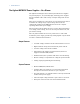
1 Quick Reference The Agilent N5700 DC Power Supplies – At a Glance The Agilent Technologies Series N5700 System DC Power Supplies are general-purpose, 1U (rack unit) high, switching power supplies that are available with a wide variety of output voltage and current ratings. These power supplies are power-factor corrected and operate from a worldwide AC voltage range. Output voltage and current are continuously displayed and LED indicators show the complete operating status of the power supply.
Quick Reference 1 Programmable Functions • Output voltage and current setting. • Output voltage and current measurement. • Output voltage and current trigger setting. • Output On/Off control. • Over-current protection setting. • Over-voltage protection setting and readback. • Under-voltage limit setting and readback. • Start-up mode (either last setting or reset mode) • Status register setting and readback.
1 Quick Reference The Front Panel - At a Glance 3 2 1 VOLTAGE 4 DC VOLTS 5 6 CURRENT DC AMPS CV CC PROT FINE LIMIT/ 16 14 OVP UVL OCP/488 LAN OUT ON POWER 19 18 1 – VOLTAGE knob 17 15 13 11 9 12 7 10 8 Voltage function: Adjusts the output voltage, the over-voltage protection level, and the under-voltage limit. If over-voltage protection or under-voltage limits have been set, you cannot program the output voltage outside those limits.
Quick Reference 9 – LAN button 1 View address: Press LAN to view the IP and Ethernet address. The display first scrolls through the four segments of the IP address, followed by the six segments of the Ethernet (EA) address. Press any key to turn the address display off. Reset address: Press and hold the LAN button for three seconds. Pressing the LAN button again while the message “LAn rES” is displayed resets the LAN configuration to the factory-shipped settings (see chapter 4 for settings).
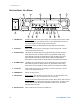
1 Quick Reference The Rear Panel – At a Glance 8 9 10/100 Ethernet LINK TX GPIB J2 SW1 +S+LS NC -LC-S ! ! +V -V J1 ON 1 2 3 4 5 6 7 8 9 OFF ANALOG PROGRAMMING AC INPUT NOT ACTIVE 80V - 600V 750W 2 7 6 5 4 6V - 60V 1500W 1 – AC input connector Wire clamp connector for 1500W output models. IEC connector for 750W output models. 2 – DC output connector Wire clamp connector for 80V to 600V models. Bus bars for 6V to 60V models.
Quick Reference 1 J2 Sense Connector 1 – Remote sense (+) 2 – Local sense (+) 3 – Not used 4 – Local sense (–) 5 – Remote sense (–) The factory-shipped configuration is shown in the figure. SW1 Setup Switch 1 2 3 4 5 6 7 8 9 The factory-shipped setting is Down for all switches. 1 – Output voltage, voltage programming Down: The output voltage is programmed by the front panel. The output voltage is programmed by the external voltage signal.
1 Quick Reference J1 Analog Programming Connector Current Program Voltage Program Local / Analog Voltage Monitor Common (-S) CV / CC 13 25 12 24 11 10 23 22 9 21 8 7 20 19 6 18 5 17 Chassis Common Chassis Common Enable + 4 3 16 15 2 1 14 Parallel Current Monitor Current Prog. Return Voltage Prog. Return Local / Analog State Enable -Shut Off Power Supply OK The factory-shipped default configuration is Local operation, which does not require connection to J1.
2 Installation General Information.......................................................................................... 16 Inspecting the Unit ........................................................................................... 17 Installing the Unit.............................................................................................. 17 Connecting the Line Cord ................................................................................ 19 Connecting the Load........................
2 Installation General Information Models 750 W Models 1500 W Models N5741A – N5749A N5761A – N5769A N5750A – N5752A N5770A – N5772A Items Supplied Item Description Power Cord A power cord appropriate for your location 750W units are supplied with terminated power cords 1500W units are supplied with unterminated power cords Strain relief assembly A strain relief assembly for unterminated power cords (only used for 1500W units) AC input cover A cover for the AC input on which the strain relief
Installation 2 Inspecting the Unit When you receive your power supply, inspect it for any obvious damage that may have occurred during shipment. If there is damage, notify the shipping carrier and nearest Agilent Sales and Service Office immediately. Refer to Appendix C for more information. Until you have checked out the power supply, save the shipping carton and packing materials in case the unit has to be returned.
2 Installation Rack Installation CAUTION Ensure that the screws used to attach the rack slide kit do not penetrate more than 6 mm into the sides of the unit. Do not block the air intake at the front, or the exhaust at the rear of the unit. The Agilent N5700 power supplies can be mounted in a standard 19inch rack panel or cabinet. They are designed to fit in one rack unit (1U) of space. To install the power supply in a rack: 1.
Installation 2 Connecting the Line Cord WARNING SHOCK HAZARD The power cord provides a chassis ground through a third conductor. Be certain that your power outlet is of the three-conductor type with the correct pin connected to earth ground. FIRE HAZARD Use only the power cord that was supplied with your instrument. Using other types of power cords may cause overheating of the power cord, resulting in fire. NOTE The detachable power cord may be used as an emergency disconnecting device.
2 Installation • Unscrew the base of the strain relief from the wire compression nut. Place the locknut inside the AC input cover with the flat side of the nut against the cover. Insert the base through the outside opening of the AC input cover. Screw the base securely onto the locknut from the outside (17 ft-lbs). • Slide the wire compression nut over the AC cable. Insert the stripped wires through the strain relief base until the outer cable jacket is flush with the inside edge of the base.
Installation 2 Connecting the Load WARNING SHOCK HAZARD Turn off AC power before making rear panel connections. All wires and straps must be properly connected with screws securely tightened.
2 Installation Cross section (mm2) Resistance Ω/kilometer Maximum length in meters to limit voltage to 1 V for 5 A for 10 A for 20A for 50A for 150A 2.5 4 6 10 16 25 35 8.21 5.09 3.39 1.95 1.24 0.795 0.565 24.0 39.2 59.0 102 160 250 354 12.0 18.6 29.4 51.2 80.0 125 177 6.0 9.8 14.8 25.6 40.0 62.0 88.0 2.4 4.0 5.8 10.2 16.0 25.2 35.4 0.8 1.4 2.0 3.4 5.4 8.4 11.
Installation 2 Install the shield after you have finished connecting the load wires. Shield Load Connections for 80V to 600V Models WARNING SHOCK HAZARD Hazardous voltages may exist at the outputs and the load connections when using a power supply with a rated output greater than 40V. To protect personnel against accidental contact with hazardous voltages, ensure that the load and its connections have no accessible live parts.
2 Installation • Loosen the two chassis screws marked A halfway. • Assemble the protective shield to the chassis and tighten the two screws to fix the shield to the chassis. Screw tightening torque: 4.8-5.3 in-lb A A • Tighten the wires to one of the shield sides using tie-wrap or equivalent. Refer to the following figure. Load wires • Ensure that the wire length inside the shield is long enough to provide proper strain relief.
Installation 2 The J2 connector plug specifications are as follows: Plug Type: MC 1.5/5-ST-3.81, Phoenix Wire Size: AWG 28 to AWG 16 Stripping Length: 7 mm (0.28 in.) Torque: 0.22 – 0.25 Nm (1.95 – 2.21 in-lb.) Local Sensing The power supply is shipped with the rear panel J2 sense connector wired for local sensing of the output voltage. With local sensing, the output voltage regulation is made at the output terminals.
2 Installation To configure the power supply for remote sensing: • Turn off the power supply. • Remove the local sense jumpers from the J2 connector. • Connect the negative sense lead to terminal 5 (-S) and the positive sense lead to terminal 1 (+S). Make sure that the connector plug is securely inserted into the connector body. • Turn on the power supply. Load lines. Twisted pair shortest length possible. +V Power Supply + Load -V - Rem.sense -Local sense +Local sense +Rem.
Installation 2 If remotely located distribution terminals are used, as shown in the following figure, the power supply output terminals should be connected to the remote distribution terminals by a pair of twisted and/or shielded wires. Connect each load to the distribution terminals separately. Remote voltage sensing is recommended under these circumstances. Sense either at the remote distribution terminals or, if one load is more sensitive than the others, directly at the critical load.
2 Installation Grounding the Output The output of the power supply is isolated from earth ground. Either positive or negative voltages can be obtained from the output by grounding (or "commoning") one of the output terminals. Always use two wires to connect the load to the output regardless of where or how the system is grounded.
Installation 2 +S -S -S Twisted pair +S MASTER POWER SUPPLY +V As short as possible -V Twisted pair +S J1-25 Parallel Current Program J1-8 J1-12 J1-10 SLAVE POWER SUPPLY -S +S LOAD +V -V -S Twisted pair -S +S Remote Sensing One of the units operates as a master and the remaining units are slaves. The slave units operate as controlled current sources following the master output current.
2 Installation Setting the Over-Voltage Protection The master unit OVP should be programmed to the desired OVP level. The OVP of the slave units should be programmed to a higher value than the master. When the master unit shuts down, it programs the slave unit to zero output voltage. If a slave unit shuts down when its OVP is set lower than the master output voltage, only that unit shuts down and the remaining slave units will supply all the load current.
Installation +LS +S +LS +S POWER SUPPLY -LS + - POWER SUPPLY (*) -S -LS + + - (*) -S + LOAD LOAD - +LS +S POWER SUPPLY -LS + - 2 POWER SUPPLY (*) Diodes are user supplied. (*) - +LS +S -LS -S + - (*) -S Remote Sensing Local Sensing Refer to the following figure for typical connections of series power supplies configured as a positive and a negative output. +LS +S POWER SUPPLY + -LS -S - (*) + - +LS +S POWER SUPPLY + - (*) (*) Diodes are user supplied.
2 Installation J1 Connector Connections WARNING SHOCK HAZARD There is a potential shock hazard at the J1 connector when using a power supply with a rated output greater than 40V. Ensure that the load wiring insulation rating is greater than or equal to the maximum output voltage of the power supply. External programming and monitoring signal are located on the J1 connector. The power supply is shipped with a mating plug that makes it easy for you to make your wire connections.
3 Operating the Power Supply Locally Turn-On Check-Out ........................................................................................... 34 Normal Operation.............................................................................................. 36 Protection Functions ........................................................................................ 37 Output On/Off Controls....................................................................................
3 Operating the Power Supply Locally Turn-On Check-Out Before Check-Out Ensure that the power supply is configured as follows: WARNING • The unit is connected to an appropriate AC source as described in chapter 2. • The POWER switch is in the off position. • Sense connector pins 1 and 2 are jumpered; sense connector pins 4 and 5 are jumpered. • All switches on Connector J2 are in the down position. SHOCK HAZARD Be aware that hazardous voltages can be present on the output terminals.
Operating the Power Supply Locally 3 UVL Check • Press the OVP/UVL button twice so that the DC AMPS display indicates UUL. The DC VOLTS display shows the UVL level. • Use the voltage knob and set the UVL level of the unit to 50% of its full-scale voltage rating or 30 volts, whichever is lower. • Wait a few seconds until the DC VOLTS display returns to show the output voltage. • Use the voltage knob and lower the output voltage of the unit until it approaches the UVL setting.
3 Operating the Power Supply Locally Normal Operation The power supply has two basic operating modes: constant voltage and constant current mode. In constant voltage mode, the power supply regulates the output voltage at the selected value, while the load current varies as required by the load. In constant current mode, the power supply regulates the output current at the selected value, while the voltage varies as required by the load.
Operating the Power Supply Locally 3 CV/CC Mode Crossover If the power supply is in constant voltage mode and the load current increases above the current limit setting, the power supply switches to constant current mode. If the load decreases below the current limit setting, the power supply switches to constant voltage mode. CV/CC Signal CAUTION Do not connect the CV/CC signal to a voltage source higher than 30VDC.
3 Operating the Power Supply Locally • Press the OUT ON button to turn the output on. • Turn the AC power off, wait a few seconds, and turn it on. • Turn the output off, then on again using the Shut Off pin on the J1 connector. This only applies in Auto-Restart mode. • If the OVP continues to trip, try lowering the output voltage below the OVP setting, or raising the OVP setting. Under-Voltage Limit The under-voltage limit prevents adjustment of the output voltage below a certain limit.
Operating the Power Supply Locally 3 Over-Temperature Protection The over-temperature protection circuit shuts down the power supply before the internal components can exceed their safe internal operating temperature. This can occur if there is a cooling fan failure. When an OTP condition occurs, the output is disabled, the display shows O7P, the PROT indicator blinks, and the OT status bit is set in the Questionable Condition status register.
3 Operating the Power Supply Locally Output On/Off Controls The Output On/Off controls turn the power supply output on or off. This can be done with the front panel OUT ON button or from the rear panel J1 connector. With the output off, adjustments can be made to the power supply or the load without shutting off AC power. OUT ON button The OUT ON button can be pressed at any time to enable or disable the power supply output.
Operating the Power Supply Locally 3 To re-enable the output after it has shut down, you must disable the Shut-Off signal. In Auto-Restart mode, operation resumes automatically. In Safe-Start mode the Shut-Off function is latched. You must also press the OUT ON button or send an OUTPut:PROTection:CLEar command to resume operation. The Shut-Off function can be used to shut down multiple power supplies in a daisy-chain fashion as explained later in this chapter.
3 Operating the Power Supply Locally Power Supply OK Signal The Power Supply OK signal on the J1 connector indicates a fault condition in the power supply. J1 pin 16 is a TTL output signal. Pins 2 and 3, which are connected internally, are the signal common. All pins are optically isolated from the power supply output. With no fault, Power Supply OK is high, with a maximum source current of 2mA. When a fault occurs, Power Supply OK is low, with a maximum sink current of 1mA.
Operating the Power Supply Locally 3 The J1 connector also provides monitoring signals for the output voltage and output current. The programming range and monitoring signal range can be selected using the SW1 setup switch. NOTE With analog programming enabled, you cannot program the output voltage or current using the front panel knobs or the remote interface. However, you can read back output voltage or current from the front panel or the remote interface.
3 Operating the Power Supply Locally • Set the programming sources to the desired levels and turn the power supply on. Adjust the programming sources to change the power supply output. The analog control circuits let you set the output voltage and current limit up to 5% over the model-rated maximum value. The power supply will operate within the extended range, however it is not recommended to operate the power supply over its voltage and current rating, and performance in this region is not guaranteed.
Operating the Power Supply Locally • 3 Set the programming resistors to the desired resistance and turn the power supply on. Adjust the resistors to change the power supply output. The analog control circuits let you set the output voltage and current limit up to 5% over the model-rated maximum value. The power supply will operate within the extended range, however it is not recommended to operate the power supply over its voltage and current rating, and performance in this region is not guaranteed.
4 Operating the Power Supply Remotely Connecting to the Interfaces .......................................................................... 48 SCPI Commands – an Introduction................................................................ 58 This chapter contains information on how to configure the three remote interfaces that are provided on the back of the instrument.
4 Operating the Power Supply Remotely Connecting to the Interfaces The Agilent N5700 power supplies support remote interface communication using a choice of three interfaces: GPIB, USB, and LAN. All three interfaces are live at power-on. GPIB Interface NOTE For detailed information about GPIB interface connections, refer to the Agilent Technologies USB/LAN/GPIB Interfaces Connectivity Guide, located on the Automation-Ready CD-ROM that is shipped with your product.
Operating the Power Supply Remotely 4 USB Interface NOTE For detailed information about USB interface connections, refer to the Agilent Technologies USB/LAN/GPIB Interfaces Connectivity Guide, located on the Automation-Ready CD-ROM that is shipped with your product. The following steps will help you quickly get started connecting your USB-enabled instrument to the Universal Serial Bus (USB). The following figure illustrates a typical USB interface system. USB Cable PC Connect to USB port on PC.
4 Operating the Power Supply Remotely Connecting to a Site LAN A site LAN is a local area network in which LAN-enabled instruments and computers are connected to the network through routers, hubs, and/or switches. They are typically large, centrally-managed networks with services such as DHCP and DNS servers.
Operating the Power Supply Remotely 4 Connecting to a Private LAN: A private LAN is a network in which LAN-enabled instruments and computers are directly connected, and not connected to a site LAN. They are typically small, with no centrally-managed resources. To Network Interface Card (NIC) PC NOTE To LAN Port CAT5 Crossover Cable Instrument 1 If you have not already done so, install the Agilent IO Libraries Suite from the Automation-Ready CD-ROM that is shipped with your product.
4 Operating the Power Supply Remotely 5 You can now use Interactive IO within the Connection Expert to communicate with your instrument, or you can program your instrument using the various programming environments. You can also use the Web browser on your computer to communicate with the instrument as described under “Using the Web Server”.
Operating the Power Supply Remotely 4 Using Telnet In an MS-DOS Command Prompt box type: telnet hostname 5024 where hostname is the N5700 hostname or IP address, and 5024 is the instrument’s telnet port. You should get a Telnet session box with a title indicating that you are connected to the power supply. Type the SCPI commands at the prompt. Using Sockets Agilent instruments have standardized on using port 5025 for SCPI socket services.
4 Operating the Power Supply Remotely Service requests are enabled for control sockets using the Service Request Enable register. Once service requests have been enabled, the client program listens on the control connection. When SRQ goes true the instrument will send the string “SRQ +nn” to the client. The “nn” is the status byte value, which the client can use to determine the source of the service request.
Operating the Power Supply Remotely 4 Subnet Mask This value is used to enable the instrument to determine if a client IP address is on the same local subnet. When a client IP address is on a different subnet, all packets must be sent to the Default Gateway. Default Gateway This value is the IP Address of the default gateway that allows the instrument to communicate with systems that are not on the local subnet, as determined by the subnet mask setting.
4 Operating the Power Supply Remotely Factory-shipped LAN Settings The factory-shipped LAN settings documented in the following table are optimized for connecting your power supply to a site network. They should also work well for other network configurations. The factory-shipped settings can be restored by pressing and holding the front panel LAN button for three seconds. Pressing the LAN button again while the message “LAn rES” is displayed resets the LAN settings.
Operating the Power Supply Remotely 4 4 Enable the LAN and, optionally, the built-in Web server using the applicable check boxes. 5 Click the Set button to save all the settings information. 6 Connect the LAN cable to your instrument and computer. Reboot the instrument. Wait for the instrument to configure the new LAN settings. 7 View the LAN settings by clicking the LAN Status tab. Click the Refresh button to update the display with the assigned IP Address and Subnet Mask.
4 Operating the Power Supply Remotely SCPI Commands – an Introduction SCPI (Standard Commands for Programmable Instruments) is an ASCII-based instrument command language designed for test and measurement instruments. SCPI commands are based on a hierarchical structure, also known as a tree system. In this system, associated commands are grouped together under a common node or root, thus forming subsystems. Subsystem commands perform specific power supply functions.
Operating the Power Supply Remotely 4 previous command in the message up to and including the last colon separator. An example of a message with two commands is: OUTPut:STATe ON;PROTection:CLEar which shows the use of the semicolon separating the two commands, and also illustrates the command path concept.
4 Operating the Power Supply Remotely In the previous examples, the upper-case letters indicate the abbreviated spelling for the keyword. For shorter program lines, you can send the abbreviated form. For better program readability, you can send the long form. For example, VOLT and VOLTage are both acceptable forms. You can use upper- or lower-case letters. Therefore, VOLTAGE, Volt, and volt are all acceptable. Other forms, such as VOL and VOLTAG, generate an error.
Operating the Power Supply Remotely 4 Parameter Types Data programmed or queried from the power supply is ASCII. The data may be numerical or character string. Numeric Parameters Symbol Response Formats Digits with an implied decimal point assumed at the right of the least-significant digit. Examples: 273 Digits with an explicit decimal point. Example: 27.3 Digits with an explicit decimal point and an exponent. Example: 2.
4 Operating the Power Supply Remotely SCPI Command Completion SCPI commands sent to the power supply are processed either sequentially or in parallel. Sequential commands finish execution before a subsequent command begins. Parallel commands allow other commands to begin executing while the parallel command is still executing. The following is a list of parallel commands. You should use some form of command synchronization as discussed in this section before assuming that these commands have completed.
5 Language Reference SCPI Command Summary................................................................................ 64 Calibration Commands ..................................................................................... 66 Measure Commands......................................................................................... 67 Output Commands ............................................................................................ 68 Source Commands.........................................
5 Language Reference SCPI Command Summary NOTE Some [optional] commands have been included for clarity. All settings commands have a corresponding query.
Language Reference SCPI Command 5 Description STATus :OPERation [:EVENt]? :CONDition? :ENABle :NTRansition :PTRansition :PRESet :QUEStionable [:EVENt]? :CONDition? :ENABle :NTRansition :PTRansition Returns the value of the questionable event register Returns the value of the questionable condition register Enables specific bits in the Event register Sets the Negative transition filter Sets the Positive transition filter SYSTem :COMMunicate :RLSTate LOCal | REMote | RWLo
5 Language Reference Calibration Commands Calibration commands let you enable and disable the calibration mode, change the calibration password, calibrate current and voltage programming, and store new calibration constants in nonvolatile memory. NOTE If calibration mode has not been enabled with CALibrate:STATe, the calibration commands will generate an error. CALibrate:CURRent[:LEVel] This command initiates the calibration of the output current.
Language Reference 5 CALibrate:STATe ON|OFF [,] CALibrate:STATe? This command enables/disables calibration mode. Calibration mode must be enabled for the power supply to accept any other calibration commands. The first parameter specifies the enabled or disabled state On (1) or Off (0). The second parameter is the password. A password is required if calibration mode is being enabled and the existing password is not 0.
5 Language Reference Output Commands Output commands enable the output, power-on, and protection functions. OUTPut[:STATe] ON|OFF OUTPut[:STATe]? This command enables or disables the specified output(s). The enabled state is On (1); the disabled state is Off (0). The state of a disabled output is a condition of zero output voltage and a zero source current (see *RST). The query returns 0 if the output is off, and 1 if the output is on. The *RST value = Off.
Language Reference 5 Source Commands Source commands program the voltage, current, triggered, and protection functions. [SOURce:]CURRent[:LEVel][:IMMediate][:AMPLitude] |MIN|MAX [SOURce:]CURRent[:LEVel][:IMMediate][:AMPLitude]? [MIN|MAX] [SOURce:]CURRent[:LEVel]:TRIGgered[:AMPLitude] |MIN|MAX [SOURce:]CURRent[:LEVel]:TRIGgered[:AMPLitude]? [MIN|MAX] These commands set the immediate and the triggered output current level. The values are programmed in amperes.
5 Language Reference [SOURce:]VOLTage:LIMit:LOW |MIN|MAX [SOURce:]VOLTage:LIMit:LOW? [MIN|MAX] This command sets the low voltage limit of the output. When a low voltage limit has been set, the instrument will ignore any programming commands that attempt to set the output voltage below the low voltage limit. The*RST value = Max. The range of values that can be programmed for this command is coupled with the immediate voltage level setting.
Language Reference 5 Status Commands Status commands program the power supply’s status registers. As shown in the following figure, the power supply has three groups of status registers; Operation, Questionable, and Standard Event. The Operation and Questionable status groups each consist of the Condition, Enable, and Event registers and NTR and PTR filters.
5 Language Reference The Standard Event group is programmed with Common commands as described later in this section. Common commands also control additional status functions such as the Service Request Enable and the Status Byte registers. STATus:PRESet This command sets all defined bits in the Operation and Questionable PTR registers. The command clears all defined bits in the Operation and Questionable NTR and Enable registers.
Language Reference 5 STATus:OPERation:NTR STATus:OPERation:PTR STATus:OPERation:NTR? STATus:OPERation:PTR? These commands set or read the value of the Operation NTR (Negative-Transition) and PTR (Positive-Transition) registers.
5 Language Reference STATus:QUEStionable:ENABle STATus:QUEStionable:ENABle? This command and its query set and read the value of the Questionable Enable register. This register is a mask for enabling specific bits from the Questionable Event register to set the questionable summary bit (QUES) of the Status Byte register. This bit (bit 3) is the logical OR of all the Questionable Event register bits that are enabled by the Questionable Status Enable register. The Preset value = 0.
Language Reference 5 *ESE *ESE? This command programs the Standard Event Status Enable register bits. The programming determines which events of the Standard Event Status Event register (see *ESR?) are allowed to set the ESB (Event Summary Bit) of the Status Byte register. A "1" in the bit position enables the corresponding event. All of the enabled events of the Standard Event Status Event Register are logically OR-ed to cause the Event Summary Bit (ESB) of the Status Byte Register to be set.
5 Language Reference *SRE *SRE? This command sets the condition of the Service Request Enable Register. This register determines which bits from the Status Byte Register are allowed to set the Master Status Summary (MSS) bit and the Request for Service (RQS) summary bit. A 1 in any Service Request Enable Register bit position enables the corresponding Status Byte Register bit and all such enabled bits then are logically OR-ed to cause Bit 6 of the Status Byte Register to be set.
Language Reference 5 System Commands System commands control system functions that are not directly related to output control, measurement, or status functions. Common commands are also used to control system functions. SYSTem:COMMunicate:RLSTate LOCal|REMote|RWLock SYSTem:COMMunicate:RLSTate? This command configures the remote/local state of the instrument according to the following settings. LOCal The instrument is set to front panel control (front panel keys are active).
5 Language Reference *IDN? This query requests the power supply to identify itself. It returns a string of four fields separated by commas. Agilent Technologies xxxxxA 0 , Manufacturer Model number followed by a letter suffix Zero or serial number if available Firmware revision, power supply revision *OPT? This query requests the unit to identify any installed options. A 0 indicates no options are installed.
Language Reference 5 Trigger Commands Trigger commands consist of the Abort, Trigger, and Initiate commands. Initiate commands initialize the trigger system. Trigger commands control the triggering of the power supply. ABORt This command cancels any trigger actions in progress and returns the trigger system to the IDLE state, unless INIT:CONT is enabled. It also resets the WTG bit in the Status Operation Condition register. ABORt is executed at power-on and upon execution of *RST.
6 Programming Examples Output Programming Example ........................................................................ 82 Trigger Programming Example........................................................................ 84 This chapter contains several example programs to help you develop programs for your own application.
6 Programming Examples Output Programming Example This program sets the voltage, current, over-voltage, and the overcurrent protection. It turns the output on and takes a voltage measurement. When done, the program checks for instrument errors and gives a message if there is an error.
Programming Examples 6 ' Set the over voltage level .WriteString "VOLT:PROT:LEV " & Str$(overVoltSetting) ' Turn on over current protection .WriteString "CURR:PROT:STAT " & Str$(overCurrOn) ' Set the current level .WriteString "CURR " & Str$(CurrSetting) ' Turn the output on .WriteString "OUTP ON" ' Make sure that the output is on before continuing .WriteString "*OPC?" .ReadString ' Measure the voltage .WriteString "Meas:Volt?" measVolt = .
6 Programming Examples Trigger Programming Example This example illustrates how to set up and trigger a voltage and current change. The voltage is measured before and after the trigger.
Programming Examples 6 ' Set the voltage .WriteString "VOLT" & Str$(VoltSetting) ' Set the current level .WriteString "CURR " & Str$(CurrSetting) ' Set the triggered voltage and current levels .WriteString "VOLT:TRIG " & Str$(trigVoltSetting) .WriteString "CURR:TRIG " & Str$(trigCurrSetting) ' Turn the output on .WriteString "OUTP ON" ' Make sure that the output is on .WriteString "*OPC?" .ReadString ' Measure the voltage before triggering the change .WriteString "MEAS:VOLT?" MeasureVolt = .
Appendix A Specifications Performance Specifications ............................................................................ 88 Supplemental Characteristics ......................................................................... 89 Outline Diagram................................................................................................. 91 This chapter lists the specifications and supplemental characteristics of the Agilent N5700 power supplies.
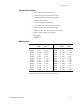
Appendix A Specifications Performance Specifications Agilent Models N5741A – N5752A and N5761A – N5772A N5741A N5742A N5761A N5762A Model N5743A N5763A N5744A N5764A N5745A N5765A N5746A N5766A N5747A N5767A N5748A N5768A N5749A N5769A N5750A N5770A N5751A N5771A N5752A N5772A DC Output Ratings: NOTE 1 Voltage Current 750W 6V 8V 12.5V 20V 30V 40V 60V 80V 100V 150V 300V 600V 100A 90A 60A 38A 25A 19A 12.5A 9.5A 7.5A 5A 2.5A 1.
Specifications Appendix A Supplemental Characteristics Agilent Models N5741A – N5752A and N5761A – N5772A Model N5741A N5742A N5761A N5762A N5743A N5763A N5744A N5764A N5745A N5765A N5746A N5766A N5747A N5767A N5748A N5768A N5749A N5769A N5750A N5770A N5751A N5771A N5752A N5772A Output Response Time: (to settle to within ±1.0% of the rated output, with a resistive load) Up, full load 0.08s 0.08s 0.08s 0.08s 0.08s 0.08s 0.08s 0.15s 0.15s 0.15s 0.15s 0.25s Down, full load 0.05s 0.
Appendix A Specifications Agilent Models N5741A – N5752A and N5761A – N5772A Model N5741A N5742A N5761A N5762A N5743A N5763A N5744A N5764A N5745A N5765A N5746A N5766A N5747A N5767A N5748A N5768A N5749A N5769A N5750A N5770A N5751A N5771A N5752A N5772A Series and Parallel Capability: Parallel operation Up to 4 identical units can be connected in master/slave mode with single–wire current balancing Series operation Up to 2 identical units can be connected using external protection diodes Sava
Specifications Appendix A Outline Diagram VOLTAGE I 43.6mm A OVP PROT FINE LIMIT UVL N5749A 100V/7.5A 750W O DC VOLTS System DC Power Supply DC AMPS CURRENT OCP REM OUT ON POWER 482.8+/-1.0mm 422.8+/-1.0mm 10/100 Ethernet TX LINK GPIB J2 SW1 +S+LSNC-LC-S ON 1 2 3 4 5 6 7 8 9 OFF +V -V J1 ANALOG PROGRAMMING NOT ACTIVE AC INPUT 507.0+/-1.0mm A 57.8+/-0.5 92.0+/-0.5 A 92.0+/-0.5 21.0 A 433+/-1.0mm Strain-Relief Detail 1500W Models 3 m 5m Bus-Bar Detail 6V to 60V Models 3.
Appendix B Verification and Calibration Verification ......................................................................................................... 94 Calibration ........................................................................................................113 The verification procedures described in this appendix verify that the power supply is operating normally and is within published specifications.
Appendix B Verification and Calibration Verification Verification procedures verify that the power supply is operating normally and is within published specifications. There are two types of verification tests: Performance These tests verify that the power supply meets all of the specifications listed in Appendix A. They can also be used to verify that the power supply is properly calibrated. Calibration These procedures calibrate the power supply.
Verification and Calibration Appendix B Measurement Techniques Electronic Load Many of the test procedures require the use of a variable load capable of dissipating the required power. If a variable resistor is used, switches should be used to either; connect, disconnect, or short the load resistor. For most tests, an electronic load can be used.
Appendix B Verification and Calibration Constant Voltage Tests NOTE Refer to the appropriate test record form for the instrument settings of the model you are checking. Voltage Programming and Readback Accuracy Test category = performance, calibration This test verifies that the voltage programming and measurement functions are within specifications. 1 Turn off the power supply and connect a DVM directly across the +S and -S terminals as shown in figure A. Do not connect a load.
Verification and Calibration Appendix B CV Source Effect Test category = performance This test measures the change in output voltage that results from a change in AC line voltage from the minimum to maximum value within the line voltage specifications. 1 Turn off the power supply and connect the ac power line through a variable voltage transformer. 2 Connect a DVM and an electronic load as shown in figure A. Set the variable voltage transformer to nominal line voltage.
Appendix B Verification and Calibration 4 Program the power supply to program the output current to its maximum programmable value (Imax) and the output voltage to its full-scale value and enable the output. Let the oscilloscope run for a few seconds to generate enough measurement points. On the Agilent Infiniium scope, the maximum peak-to-peak voltage measurement is indicated at the bottom of the screen on the right side. Divide this value by 10 to get the CV peak-to-peak noise measurement.
Verification and Calibration Appendix B Constant Current Tests NOTE Refer to the appropriate test record form for the instrument settings of the model you are checking. Current Programming and Readback Accuracy Test category = performance, calibration This test verifies that the current programming and measurement functions are within specifications. 1 Turn off the power supply and connect the current shunt directly across the output. Connect the DVM across the current shunt.
Appendix B Verification and Calibration 4 With the electronic load in CV mode, set it for the output’s fullscale voltage. The CC annunciator on the front panel must be on. If it is not, adjust the load so that the voltage drops slightly. 5 Divide the voltage drop (DVM reading) across the current monitoring resistor by its resistance to convert to amps and record this value (Iout). 6 Short the electronic load.
Verification and Calibration Appendix B Test Record Form – Agilent N5741A and N5761A Agilent N5741A and N5761A Report No _______________ Date __________________ Model Minimum Specs. Results Maximum Specs. Minimum Voltage Vout Measurement Readback Both Both 0 mV Vout − 6 mV __________ __________ + 15 mV Vout + 6 mV High Voltage Vout Measurement Readback Both Both 5.994 V Vout − 12 mV __________ __________ 6.006 V Vout + 12 mV CV Load Effect Both − 2.6 mV __________ + 2.
Appendix B Verification and Calibration Test Record Form – Agilent N5742A and N5762A Agilent N5742A and N5762A Description Report No _______________ Date __________________ Model Minimum Specs. Results Maximum Specs. Minimum Voltage Vout Measurement Readback Both Both 0 mV Vout − 8 mV __________ __________ +20 mV Vout + 8 mV High Voltage Vout Measurement Readback Both Both 7.992 V Vout − 16 mV __________ __________ 8.008 V Vout + 16 mV CV Load Effect Both − 2.8 mV __________ + 2.
Verification and Calibration Appendix B Test Record Form – Agilent N5743A and N5763A Agilent N5743A and N5763A Description Report No _______________ Date __________________ Model Minimum Specs. Results Maximum Specs. Minimum Voltage Vout Measurement Readback Both Both 0 mV Vout − 12.5 mV __________ __________ + 31.25 mV Vout + 12.5 mV High Voltage Vout Measurement Readback Both Both 12.4875 V Vout − 25 mV __________ __________ 12.5125 V Vout + 25 mV CV Load Effect Both − 3.
Appendix B Verification and Calibration Test Record Form – Agilent N5744A and N5764A Agilent N5744A and N5764A Description Report No _______________ Date __________________ Model Minimum Specs. Results Maximum Specs. Minimum Voltage Vout Measurement Readback Both Both 0 mV Vout − 20 mV __________ __________ + 50 mV Vout + 20 mV High Voltage Vout Measurement Readback Both Both 19.98 V Vout − 40 mV __________ __________ 20.
Verification and Calibration Appendix B Test Record Form – Agilent N5745A and N5765A Agilent N5745A and N5765A Description Report No _______________ Date __________________ Model Minimum Specs. Results Maximum Specs. Minimum Voltage Vout Measurement Readback Both Both 0 mV Vout − 30 mV __________ __________ + 75 mV Vout + 30 mV High Voltage Vout Measurement Readback Both Both 29.97 V Vout − 60 mV __________ __________ 30.
Appendix B Verification and Calibration Test Record Form – Agilent N5746A and N5766A Agilent N5746A and N5766A Description Report No _______________ Date __________________ Model Minimum Specs. Results Maximum Specs. Minimum Voltage Vout Measurement Readback Both Both 0 mV Vout − 40 mV __________ __________ +100 mV Vout + 40 mV High Voltage Vout Measurement Readback Both Both 39.96 V Vout − 80 mV __________ __________ 40.
Verification and Calibration Appendix B Test Record Form – Agilent N5747A and N5767A Agilent N5747A and N5767A Description Report No _______________ Date __________________ Model Minimum Specs. Results Maximum Specs. Minimum Voltage Vout Measurement Readback Both Both 0 mV Vout − 60 mV __________ __________ + 150 mV Vout + 60 mV High Voltage Vout Measurement Readback Both Both 59.94 V Vout − 120 mV __________ __________ 60.
Appendix B Verification and Calibration Test Record Form – Agilent N5748A and N5768A Agilent N5748A and N5768A Description Report No _______________ Date __________________ Model Minimum Specs. Results Maximum Specs. Minimum Voltage Vout Measurement Readback Both Both 0 mV Vout − 80 mV __________ __________ + 200 mV Vout + 80 mV High Voltage Vout Measurement Readback Both Both 79.92 V Vout − 160 mV __________ __________ 80.
Verification and Calibration Appendix B Test Record Form – Agilent N5749A and N5769A Agilent N5749A and N5769A Description Report No _______________ Date __________________ Model Minimum Specs. Results Maximum Specs. Minimum Voltage Vout Measurement Readback Both Both 0 mV Vout − 100 mV __________ __________ + 250 mV Vout + 100 mV High Voltage Vout Measurement Readback Both Both 99.9 V Vout − 200 mV __________ __________ 100.
Appendix B Verification and Calibration Test Record Form – Agilent N5750A and N5770A Agilent N5750A and N5770A Description Report No _______________ Date __________________ Model Minimum Specs. Results Maximum Specs. Minimum Voltage Vout Measurement Readback Both Both 0 mV Vout − 150 mV __________ __________ + 375 mV Vout + 150 mV High Voltage Vout Measurement Readback Both Both 149.85 V Vout − 300 mV __________ __________ 150.
Verification and Calibration Appendix B Test Record Form – Agilent N5751A and N5771A Agilent N5751A and N5771A Report No _______________ Description Date __________________ Model Minimum Specs. Results Maximum Specs. Minimum Voltage Vout Measurement Readback Both Both 0 mV Vout − 300 mV __________ __________ + 750 mV Vout + 300 mV High Voltage Vout Measurement Readback Both Both 299.7 V Vout − 600 mV __________ __________ 300.
Appendix B Verification and Calibration Test Record Form – Agilent N5752A and N5772A Agilent N5752A and N5772A Report No _______________ Description Date __________________ Model Minimum Specs. Results Maximum Specs. Minimum Voltage Vout Measurement Readback Both Both 0 mV Vout − 600 mV __________ __________ + 1,500 mV Vout + 600 mV High Voltage Vout Measurement Readback Both Both 599.4 V Vout − 1.2 V __________ __________ 600.6 V Vout + 1.
Verification and Calibration Appendix B Calibration Refer to the “Equipment Required” section in this appendix for a list of the equipment required for calibration. A general outline of the procedure is as follows: As shipped from the factory the calibration password is 0, which means password protection is removed and the ability to enter calibration mode is unrestricted. If a password has subsequently been set, you must enter the correct password - otherwise an error will occur.
Appendix B Verification and Calibration Step 5. Select the first voltage calibration point. CAL:LEV P1 *OPC? Step 6. Measure the output voltage and enter the data. CAL:DATA Step 7. Select the second voltage calibration point. CAL:LEV P2 *OPC? Step 8. Measure the output voltage and enter the data. CAL:DATA Step 9. Exit calibration mode. CAL:STAT OFF Current Programming and Measurement Calibration Step 1. Connect a precision shunt resistor to an output.
Appendix C Service Types of Service Available.............................................................................116 Repackaging for Shipment.............................................................................116 Operating Checklist.........................................................................................116 Error Messages ...............................................................................................
Appendix C Service Types of Service Available If your instrument fails during the warranty period, Agilent Technologies will replace or repair it free of charge. After your warranty expires, Agilent Technologies will replace or repair it at a competitive price. Contact your nearest Agilent Technologies Service Center. They will arrange to have your instrument repaired or replaced.
Service Appendix C Symptom Check Action No output. All displays and indicators are blank. Is the AC power cord defective? Check continuity. Replace if necessary. Is the AC input voltage within range? Check AC input voltage. Connect to appropriate voltage source. Output is present momentarily, but shuts off quickly. Display indicates AC. Does the AC source voltage sag when a load is applied? Check AC input voltage. Connect to appropriate voltage source.
Appendix C Service Error Messages Displaying the SCPI error queue The entire error queue is read, then emptied, using the following command: SYST:ERR? Error List The following table documents the various error messages that the power supply supports: 118 Error Device-dependent Errors (these errors set Standard Event Status register bit #3) 0 No error This is the response to the ERR? query when there are no errors.
Service Appendix C Command Errors (these errors set Standard Event Status register bit #5) −100 Command error Generic syntax error. −101 Invalid character An invalid character was found in the command string. −102 Syntax error Invalid syntax was found in the command string. Check for blank spaces. −103 Invalid separator An invalid separator was found in the command string.
Appendix C Service Command Errors (continued) −141 Invalid character data Either the character data element contains an invalid character, or the element is not valid. −144 Character data too long The character data element contains more than 12 characters. −148 Character data not allowed A discrete parameter was received, but a string or numeric parameter was expected. −150 String data error Generic string data error −151 Invalid string data An invalid character string was received.
Service Appendix C Execution Errors (continued) −231 Data questionable The measurement accuracy is suspect. −232 Invalid format The data format or structure is inappropriate. −233 Invalid version The version of the data format is incorrect to the instrument. −240 Hardware error The command could not be executed because of a hardware problem with the instrument. −241 Hardware missing The command could not be executed because of missing hardware, such as an option.
Appendix D Compatibility Differences – In General ................................................................................124 Compatibility Command Summary ...............................................................125 The Agilent N5700 power supplies are programmatically compatible with the Agilent 603xA power supplies. This means that you can remotely program the Agilent N5700 power supplies using the same commands that are used to program the 603xA power supplies.
Appendix D Compatibility Differences – In General The following table documents the general differences between the way Compatibility commands work on the Agilent N5700 power supplies and the way they worked on the Agilent 603xA power supplies. Item Differences Queries The Agilent N5700 will respond to multiple queries. It will not allow a space separator between numbers.
Compatibility Appendix D Compatibility Command Summary The following table documents the compatibility commands that the Agilent N5700 power supplies support. All compatibility commands are accepted; however, some commands do nothing. Compatibility Command Description Similar SCPI Command ASTS? Queries the accumulated status (ASTS). The response represents the sum of the binary weights of the ASTS register bits. The ASTS register is set to the present status after being queried.
Appendix D Compatibility Compatibility Command Description Similar SCPI Command OVP Sets the over-voltage trip point. VOLT:PROT:LEV OVP? Queries the present over-voltage setting. The response is a real number. VOLT:PROT:LEV? RCL Recalls the saved settings. There are up to 16 store/recall states. Saved settings must have been previously stored using the STO command. *RCL ROM? Queries the revision date of the power supply's firmware. *IDN? RST Resets any tripped protection.
Index 4 488..................................................................................11, 48 A ABOR ................................................................................... 79 AC INPUT......................................................................12, 90 1500 W units.................................................................. 19 750 W units.................................................................... 19 accessories.........................................................
Index CV/CC crossover ............................................................... 37 CV/CC signal...................................................................... 37 D daisy-chain shut down ..................................................... 42 damage................................................................................ 17 data socket ......................................................................... 53 DC AMPS .....................................................................
Index OUP ...................................................................................... 11 OUT ON ............................................................................... 10 outline diagram.................................................................. 17 output commands ............................................................. 68 OUTP ............................................................................... 68 OUTP PON STAT.......................................................
Index U UFP....................................................................................... 11 under-voltage check ......................................................... 35 under-voltage limit ............................................................ 38 USB ID string...................................................................... 49 USB interface ..................................................................... 49 UUL....................................................................
DECLARATION OF CONFORMITY According to ISO/IEC Guide 22 and CEN/CENELEC EN 45014 Responsible Party Alternate Manufacturing Site Manufacturer’s Name: Agilent Technologies, Inc.
Manual Updates The following information is provided to document the differences between front panel operation of the LXI-compliant units and the pre-LXI units. LXI-compliant units (see page 10 for additional details) Pre-LXI units CURRENT DC AMPS CC OCP/488 LAN 11 9 12 OUT ON CURRENT DC AMPS CC OCP REM 11 9 10 12 OUT ON 10 9 – LAN button View address: Press LAN to view the IP and Ethernet address. Reset address: Press and hold the LAN button for three seconds.